BOLIY PRO3600SI User manual

DIGITAL GENERATOR
BOLIY
BOLIY POWER
Pro3600Si
GENERATOR SHOP MANUAL
BOLIY POWER
©2010-2011
www.boliypower.com
Pro3600SiE (electric start)

Preface
This manual covers the construction, function and servicing procedure of the BOLIY
Pro3600Si/E model generators. This manual is principally concerned with the generator
specifications, function, troubleshooting and repair. There is a separate manual to
cover engine overhaul which includes the starting systems.
Careful observance of the instructions contained in this manual will result in safe and
quality service work.
All information, illustrations, directions and specifications included in this publication
are based on the latest product information available at the time of approval for
printing.
BOLIY POWER, reserves the right to make changes without incurring any obligation
whatever. No part of this publication may be reproduced without written permission.

Table of Contents
1. Specifications ..................................................................................................................3
1.1 Specifications.................................................................................................................3
2. Service information ..........................................................................................................6
2.1 The importance of proper service ..................................................................................6
2.2 Important safety precautions .........................................................................................6
2.3 Service rules ..................................................................................................................7
2.4 Electrical Precautions ....................................................................................................7
2.5 Serial number location...................................................................................................8
2.6 Maintenance standards .................................................................................................9
3. Maintenance .....................................................................................................................11
3.1 Regular inspection schedule .........................................................................................11
3.2 Engine oil .......................................................................................................................12
3.3 Fule leak........................................................................................................................13
3.4 Air filter maintenance.....................................................................................................14
3.5 Exhuast .........................................................................................................................15
3.6 Adjusting of valve clearance..........................................................................................16
3.7 Compress pressure ...................................................................................................17
3.8 Rating speed ...............................................................................................................18
4.0 Spark plug ......................................................................................................................19
4.1 Check engine switch..................................................................................................19
4.2 ECON switch..................................................................................................................20
4.3. Check electric components.....................................................................................20
4.4 Troubleshooting .........................................................................................................21
Section 1- Fuel related problems..................................................................................22
Section 2-Generator won't start.....................................................................................23
Section 3-No Start, no spark..........................................................................................23
Section 4-No AC Output (Inverter series) ...................................................................24
Section 5-ECON Switch failurel.....................................................................................24

1.1 SPECIFICATIONS
DIMENSIONS & WEIGHT
OVERALL LENGTH ( mm / in ) 585 / 23
OVERALL WIDTH ( mm / in ) 420 / 16.5
OVERALL HEIGHT ( mm / in ) 470 /18.5
DRY WEIGHT ( kg / lb. ) 31/ 68
GROSS WEIGHT ( kg / lb. ) 35.5 / 78
FUEL TANK CAPACITY ( L / US gal. ) 7.4 / 1.9
FUEL CONSUMPTION AT RATED OUTPUT 0.55 L/kwh
NOISE LEVEL ( at 7m ) 53-58 dB
ENGINE
TYPE 166F, OHV, AIR-COOLED, 4 * STROKE
STARTING SYSTEM RECOIL START
CYLINDER ARRANGEMENT INCLINED,SINGLE CYLINDER
BORE * STROKE ( mm/in) 66(2.6) * 50(1.97)
IGNITION SYSTEM CDI
SPARK PLUG TYPE BPR4ES(NGK)/F7RTC
GAP ( mm/in) 0.7-0.8(0.028-0.031)
DISPLACEMENT ( cc ) 171CC
RATED OUTPUT KW(HP)r/min 3.6(4.9)/3,600
FUEL UNLEADED GASOLINE
ENGINE OIL QUANTITY( L / US qt, ) 0.6(0.63)
3

GENERATOR
TYPE AC OUTPUT, Multistage
permanent-magnet generator
RATED OUTPUT ( WATTS ) 3,000
MAX OUTPUT ( WATTS ) 3,300
FULL TANK OUTPUT ( WATTS ) 13,500
RUN TIME AT 1/2 RATED LOAD 8.3 hours
RUN TIME AT RATED LOAD 4.5 hours
POWER CONVERSION RATE 85%*92%
RATED VOLTAGE ( V ) 120 & 230
RATED CURRENT ( A ) 25 & 13
DC OUTPUT( 12V / 8 A ) YES
CHARACTERISTIC
AUTOMATIC RELEASE PRESSURE YES
ELECTRO-BREAKER YES
FUEL LEVEL GAUGE YES
ENGINE Oil WARNING LIGHT YES
OVERLOAD INDICATOR LIGHT NO
AC INDICATOR LIGHT YES
ENERGY CONSERVATION CURRENT IDLING YES
INSULATION CLASS E
THE FLUCTUATION OF VOLTAGE & FREQUENCY
INSTANTANEOUS 25%
STABLE STATE ?2%
STABLE TIME ( second ) 3 sec. max.
FREQUENCY stability ?.01%
4

5
Color code
B - Black
G - Green
L - Blue
O - Orange
R - Red
W - White
Y - Yellow
P - Pink
B/W - Black/White
G/Y - Green/Yellow
W/L - White/Blue
1 - Main coil
2 - Sub coil
3 - Control unit
4 - AC indicator light/
Overload indicator light
5 - AC receptacle
6 - Ground (Earth) terminal
7 - Economy Control Switch
8 - Step Motor controller
9 - Engine switch
10 - Oil warning light
11 - Oil warning unit
12 - Oil level gauge
13 - Ignition coil
14 - Spark plug
15 - AC-CDI unit
16 - Pulsar coil
17 - Stepping motor
18 - Charge coil
19 - DC receptacle
20 - Ballast
BOLIY Pro 3600Si & 3600Si/E DSP INVERTER GENERATOR WIRING DIAGRAM

2. Service information
2.1 The importance of proper servicing
Proper servicing is essential to the safety of the operator and the reliability of the generator.
Any error or oversight made by the technician while servicing can easily result in faulty
operation and/or damage to the equipment or injury to the operator.
WARNING
* Improper servicing can cause an unsafe condition that can lead to serious injury or death.
* Follow the procedures and precautions in this shop manual carefully.
Some of the most important precautions are stated below.
2.2 Important safety precautions
Be sure you have a clear understanding of all basic shop safety practices and that you are
wearing appropriate clothing and safety equipment. When performing maintenance or repairs,
be especially careful of the following:
*Read the instructions before you begin, and be sure you have the tools and skills required
to perform the tasks safely.
*Be sure that the engine is off before you begin any maintenance or repairs. This will reduce
the possibility of several hazards:
- Carbon monoxide poisoning from engine exhaust.
- Burns from hot parts.
- Injury from moving parts.
*Do not run the engine unless the instructions tell you to do so. Keep your hands and clothing
away from rotating parts.
*To reduce the possibility of fire or explosion, exercise extreme caution when working around
gasoline. Use only a nonflammable solvent, not gasoline, to clean parts. Keep cigarettes,
sparks and flames away from all fuel-related parts.
6

2.3 Service rules
*Use genuine BOLIY or BOLIY-recommended parts and lubricants or their
equivalents. Parts that do not meet BOLIY design specifications may damage
the engine.
*Use the special tools designed for the product.
*Always install new gaskets, O-rings, etc. when reassembling components.
*Clean parts in cleaning solvent upon disassembly. Lubricate any sliding surfaces
before reassembly. After reassembly, check all parts for proper installation and
operation.
*Many screws used in this machine are self-tapping. Be aware that cross-
threading or over tightening these screws will strip the threads and ruin the
hole.
*Use only metric tools when servicing this engine. Metric bolts, nuts and screws
are not interchangeable with non metric fasteners. The use of incorrect tools
and fasteners will damage the engine.
2.4 Electrical precautions
*Hold the connector body to disconnect the connector. Do not disconnect by
pulling the wire harness. To disconnect the locking connector, be sure to unlock
first, and then disconnect.
*Check the connector terminals for bend, excessive extrusion, missing terminals,
or other abnormalities before connecting the connector.
*To connect, insert the connector as far as it goes. If the connector is a locking
type, be sure that it is locked securely.
*Check the connector cover for breakage and check whether the connector
female terminal is not opened excessively. Then, connect the connector securely.
Check the connector terminal for rust. Remove the rust using an emery paper
or equivalent material before connecting the connector.
*Set the harness clips in the specified places of the frame securely, and secure
the wire harnesses.
*Clamp the cables securely.
7

*Clamp the wire harnesses securely so that they do not interfere with the
rotating parts, moving parts and hot parts.
*Route and connect the wire harnesses properly. Be sure that the harnesses
are not slack, twisted or pulled overly taut.
*Route the wire harnesses properly so that they do not contact sharp edges
and corners and the end of the bolts and screws on the body.
*If a wire harness must contact the end of the bolts or screws or sharp edges
and corners, protect the contact part of the harness with a loom or by winding
with electrical insulating tape. If the wire harness has a grommet, set the
grommet securely.
*Take care not to pinch the wire harnesses during installation of a part. If a
wire harness has damaged insulation, repair by winding with electrical insulating
tape.
*When using an electrical tester like a volt/ohm meter or clamp on meter, read
the manufacturer抯operating instructions carefully before operating the tester.
Be sure that the tester battery is fully charged and the meter is functioning
properly
2.5 Serial number location
The engine serial number is stamped at the underside of engine side cover.
Refer to this number when ordering or making technical inquiries.
One engine serial number-one machine bar serial number
Engine serial number
Machine bar serial number
Engine serial number Machine bar serial number
8
xxxxxxxx

2.6 Maintenance standards
Engine
Part Item Standard(mm) Service limit
Cylinder Sleeve I.D. 66.02~66.04 66.15
Piston Skirt O.D 67.97~67.99 66.67
Piston-to-cylinder clearance 0.040~0.060 0.12
Piston pin O.D 15.990~16.000 .15.95
Pin-to-piston clearance 0.002~0.018 0.080
Piston ring Ring width Top 1.420~1.440 1.32
Second 1.420~1.440 1.32
Ring side clearance Top/second 0.02~0.06 0.15
Connecting rodSmall end I.D 6.006~18.017 16.07
Big end I.D 28.015~28.025 28.07
Big end oil clearance 0.046~0.060 0.12
Crankshaft Crank pin O.D. 27.960~27.975 27.90
Valve Valve clearance Intake 0.1?.2
Exhaust 0.15?.2
Stem OD Intake 5.46~5.48 5.35
Exhaust 5.45~5.47 5.35
Vessel I.D Intake/Exhaust 5.500~5.518 5.56
Clearance of valve and vessel Intake 0.020~0.058 0.1
Valve spring Free Length Intake/Exhaust 26.8 25.5
Camshaft O.D 14.966~14.984 14.92
Crankcase cover Camshaft Bearing I.D. 15.000~15.027 15.05
Cylinder block Valve lifter I.D. 8.000-8.015 8.06
Camshaft Bearing I.D. 15.000*15.02 15.05
Spark plug Clearance 0.6~0.8
Ignition coil Resistance Primary side 0.6~1.1ohm
Second side 15~19ohm
Starting relay Resistance 0.25~0.5
9

Generator
Part Item Ty p e S ta n d a r d Service
120V Limit
Ignition coil Resistance Ye l l o w / G r e e n - R e d 0 . 7 ~ 0 . 8 5 ~
Outer charging winding coil Resistance Yellow-Yellow 0.35~0.45 ~
ECON feedback winding coil Resistance White-White 0.2~0.3 ~
Control feedback Resistance Yellow-Yellow 0.4~0.45 ~
Main winding coil Resistance Blue-Blue 0.8~1.0 ~
10

3 MAINTENANCE
3.1 Maintenance schedule
Item Attention Each First month Every 3 months Every 6 months Every year or
use or 20 Hrs. or 50Hrs. or 100 Hrs. 300 Hrs.
Spark Clean-Adjust *
plug
Valve Check-Adjust *
clearance
Crankshaft Check *
System
Idile Check-Ajust *
Speed
Exhaust Check Replace *
System
Engine oil Check *
Replace * *
Air cleaner Check-Replace *
Fuel clearner Check *
Fuel pipe Check Replace *
Chock Check *
Cooling Check *
System
Start Check *
system
Clean Clean *
engine
carbon
Generator Check light *
Assembly Check *
Part
11

3.2 Engine Oil
Check Engine Oil leak
Check the engine whether or not have leak oil.
If leak replace gasket, or oil seal or O ring.
A. Checking Oil Level
Engine should be shut off and generator be on level ground when checking the oil level.
1. Check engine oil level and
oil warning light
When start whether or not the
light ray.
Light ray- add oil
No light ray- ok
2. Remove the oil dipstick,Add the proper viscosity engine oil
to the upper limit if oil level is low. Be careful to over fill.
B. Changing engine oil
(1) Remove the bottom oil screw and unscrew oil drain plug to drain used
oil.
(2) Replace the drain plug and secure tightly.
(3) Add the proper viscosity oil to the upper oil limit level.
(4) Reinstall the dipstick and screw it tightly
17Nm(1.7 m.kg ,12 ft.ib)
Enginine
A SAE#30 or 10W-30
B SAE#20 or 10W-30
C SAE10W or 10W-30
0.6L (0.53imp qt 0.63 US qt)
12
ON
OFF
AC
1
1
a
2
5
B SAE#20 or 10W-30
C SAE10W or 10W-30
0C25 C
32 80 F
F
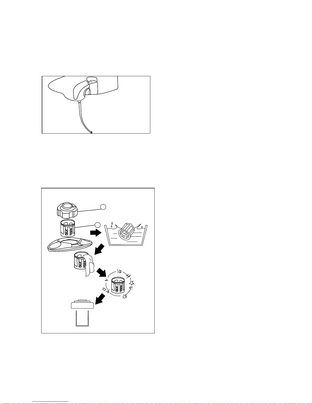
3.3 Fuel leak
1 Check
Check fuel tank, fuel switch,fuel pipe
and carburetor.
Caution:
Every 2 years replace the fuel pipe and
fuel filter.
Caution:
No fire when you clean it.
1. Take off hat.
2. get the strainer
Check strainer
Damage-replace
If ok-Clean it.
Remark: You'd better use impregnant clean it
then for dry.
13
1
2

3.4 Air Filter Maintenance
(1) Open the service door.
(2) Open the cover of air filter and take out the filter
element.
(3) Blow the inner side of filter element using compressed
air or lightly knock it to remove dirt. If any dirt remains,
change the element. Be sure to use a genuine Kipor element
to maintain a proper seal and avoid engine damage.
(4) Reinstall the filter element and close the service door.
14
Oil

3.5 Exhaust
1. Take off
Wire netting, collar clamp,and bolt etc.
2. remove carbon dust.
The exhaust as picture method to knock.
3. Clean the wire netting.
Waring: Don't use metal silk for clean. That will damage the material.
15

3.6 Adjusting valve clearance
Attention
Valve adjustment should only be performed on a cool engine.
(1) Remove back case, then take off valve cover.
(2) Pull the starter rope gently and set the piston in top dead
center (Use a stick in the spark plug hole measure the depth).
(3) Insert a feeler gauge into the gap between rocker and valve to
measure the valve clearance.
Valve Clearance
Intake: 0.1mm(0.004 in)
Exhaust:. 0.1mm (0.004in)
(4) If adjustment is necessary, proceed as follows:
a. Hold rocker axis using the wrench and loosen the lock nut.
b. Loosen the lock nut of rocker axis to gain the specified intake
and exhaust valve clearance.
c. Hold rocker axis using a wrench and tighten the lock nut.
d. Check the clearance of valve after adjustment.
16

3.7 compress pressure
Remark:
When finish adjust Valve Clearance, then measure the
compress pressure.
1. For running few mins.
2. Remove spark plug.
3. Use manometer and adapter for measure.
Manometer
Adapter
Measure:
Measure pressure you need pull the starter when the pressure finger stop, read the NO..
The standard:400-600kpa(4-6kg/cm3,57-85 psi )
Waring:
When start engine, spark plug need connect for ground, that no spark.
Measure step(At lowest level):
dripping little engine oil for cylinder, then mesure the compress pressure.
Reading Estimate
Low than no oil Cylinder,piston or piston rings are wear and tear.
The same with no oil Piston, piston rings, valve,Cylinder gasket fail.
Or need adjust valve clearance.
Measure step(At high level):
Check cylinder, valve and piston whether or not have carbon dirty.
Build in the spark plug:
18Nm(18M.kg, 13ft.ib)
17
1

3.8 Rating speed
Frist connect the speed meter
Accord with standard speed = right
If not right please check chapter3. for repair.
Check step:
1) Start engine (0% load)
2) Turn to off ECON switch.
3)Measure the speed.
3800-3950r/min
3.9 Hose
1.Check:
Hose
Crack/- Replace.
No good connect- Adjust
18
A
B
ON
OFF

Attention
Check the cylinder position should only be performed on a cool
engine.
When you take off the spark plug must keep no durity into engine.
4.0 Spark plug
1. Take off the spark plug and spark cap.
take off the spark plug.
2. Check electrode
Bad-replace
dielectric- color
3. Measure
Spark plug clearance
Ues thickness tool.
No standard- Adjust
Spark plug clearance 0.7-0.8mm
If need for clean, please use cleaner for clean
Standard spark plug BPR4ES(NSK or F7RTC)
4.1 Check engine switch.
Turn to witch for "ON" If start that's ok.
Turn "off" , the engine stop -ok.
19
a
a
b
ON
STOP
Other manuals for PRO3600SI
2
This manual suits for next models
1
Table of contents
Other BOLIY Portable Generator manuals


Popular Portable Generator manuals by other brands

Champion
Champion 40026 Owner's manual & operating instructions

Generac Power Systems
Generac Power Systems 5500XL owner's manual

Zendure
Zendure SuperBase V6400 user manual

Mosa
Mosa GE 10 YSXC Use and maintenance manual

Briggs & Stratton
Briggs & Stratton 030670-00 manual

North Star
North Star M165923V.1 owner's manual


