Bolt IoT PLATFORM User manual

BOLT IoT PLATFORM
Quick Start Guide

Setting Up
2. Download the ‘Bolt IoT’ App for
Android or iOS. You can either search for
‘Bolt IoT’ or scan the QR code below.
3. Log in using the credentials of your
cloud account on the app and follow the
instructions
Android iOS
1. The first step will be to link the Bolt
WiFi module with your Bolt Cloud
account.

Setting Up
4. How it works:
A. App connects to Bolt WiFi module over Bolt Hotspot. When you enter the
SSID (i.e. the Name of your WiFi network) and Password it is transferred to the
Bolt and stored on it.
B. When Bolt restarts the next time, it connects to the network you entered.
Note:
•If Blue LED blinks slowly then your Bolt is transmitting hotspot.
•If Blue LED blinks fast then mobile is connected to the Bolt hotspot.
•If Blue LED is stable then your Bolt is connected to the WiFi network.
•If Green LED is glowing then your Bolt is connected to the internet and cloud.
5. Once the setup is complete go back to the browser and
you will find that your device has been registered.
Troubleshooting: In case this pop up does not show up:
A. Refresh your page to find your linked device.
B. Redo the setup process via app.

Creating a Product
1. Once your Bolt WiFi module has been linked to
your Bolt Cloud account, you should start building a
product. For this click on the ‘Products’ tab.
2. Next, click on the ‘BUILD’ option. 3. Add product details and select correct
options. If you are not sure what to choose
then don't worry. You will learn about this
more in detail when you build a project in
next section.

Creating a Product
4. In the ‘Products’ tab, you will notice 3 icons in a toolbar on top.
These tools let you :
A. Configure and code for a new product.
B. Edit an existing product.
C. Link it to one of your Bolt devices.
•Now, Click on the first icon i.e. ‘Configure this Product’ to proceed.

Creating a Product
5. In the Hardware Tab, select the pins to which you will
be connecting your sensors/actuators or other
development boards like the Arduino. As an example
click on the pin marked as ‘0’.
You will learn about this more in detail when you build a
project in next section.
6. In the Code Tab, you can write the code to either
visualise the data your sensors are collecting or to
create a UI for controlling output devices.
To know more about the code you can write, check out
the Docs section.
You will learn about this more in detail when you build a
project in next section.

Project 1: Light Monitoring System
2. Once this is done, create a new product and select the A0 pin in hardware
configuration. We are choosing A0 since it is the only pin with ADC converter.
Pin A0 works with voltages from 0V to 1V. Give a suitable variable name to the
data collected by this pin.
1. Now let’s try an experiment to view sensor data on a line graph.
A. We will take a Light Dependant Resistor (LDR) which is an
analogue sensor for this experiment. You will also need a 330-
ohm resistor.
B. Connect one terminal of the resistor to the LDR.
C. The other terminal of the LDR is connected to the 3.3v terminal
of the Bolt and the other terminal of the Resistor is connected
to GND.
D. The common terminal is connected to A0 of the Bolt.
LDR
330 ohm resistor. Check the Orange,
Orange, Brown, Gold bands to identify it.

Project 1: Light Monitoring System
3. You can now write a software code in the code editor to collect the data
from the LDR. Make sure you save your file as .js since the code you have
written is in Javascript.
4. You can find this code under Docs -> Data Visualisation -> Line Graph.

Project 1: Light Monitoring System
5. In the code, make sure that you replace
your_variable_name with the variable name you used for pin
A0 at the time of product configuration.!
!
6. Click on the Save button to save the configuration followed by the
close button the exit this screen.

Project 1: Light Monitoring System
7. Click on the link button to link the configuration you just created
to a particular Bolt WiFi module.
8. Choose a suitable Bolt WiFi module to which you want to link the
configuration, select the same and click on ‘Done’.

Project 1: Light Monitoring System
9. Now we are almost done. Next, go to the homepage and
click on the ‘Deploy configuration’ button to push the
configuration you created to the ‘Bolt WiFi module’ you
linked.
10. Now wait for some time and let the data be collected. After a few minutes,
click on ‘View this device’ button to open the UI of the device.

Project 1: Light Monitoring System
11.Now you will now see a graph showing the data collected by Bolt.!
Please note that it may take a few minutes for a suitable number of data
points to be collected. We suggest you keep the device on for few hours to
get a good graph.
12.Troubleshooting:
If you see graph axis but not data points
A. Click on the ‘Deploy configuration’ button again.
B. Go back to the code Product -> Configuration -> Code and see if you
have correctly added the variable name in your code.
C. Keep the system on and wait for few minutes. Let the data be collected.
In case you don't see anything on the screen then check the code you have
written
If the problem persists, check out forum.boltiot.com or write to us on

Project 2: LED Control
1. Start with the same process of adding a new product by clicking on
the +button below the list of already created products, add details like
the name of the product.
2. Select ‘Output Devices’ under the type of connection and ‘GPIO’ as
the channel.
2. In the Hardware Tab, select any one of the Digital
pins from 0-5. As an example, we will select the 0 digital
pin and add a variable named ‘LED’. We will be
connecting our LED to this pin.

Project 2: LED Control
4. Connect your LED to the Bolt as shown in the Image.
The smaller pin of the LED is -ve (Connected to Ground)
and the larger one is +ve (Connected to Pin 0).
3. We will then go to the code editor section. You can find the code to be
copied in this section named ‘LED.html’ in the GitHub link given here - https://
github.com/Inventrom/ui-templates

Project 2: LED Control
5. Now click on the ‘X’ - Exit button which will take you to the ‘Products’ page.
Once there, click on the ‘Link’ button as shown in the image, which will allow
you to link the code to your Bolt device.You will get a popup to select your
Bolt device for linking.
6. Now go to the home page and click on the ‘API’ tab to 1. Generate API
key and 2. Enable the API key which allows you to securely access the Bolt
for controlling the pins. You can copy the API key from here to be used in the
code.

Project 2: LED Control
8. Now, click on the ‘View this Device’ Tab in the list of actions.
7. Now we are almost done. Next, go to the homepage and
click on the ‘Deploy configuration’ button to push the
configuration you created to the ‘Bolt WiFi module’ you
linked.

Project 2: LED Control
9. You will now be able to see a UI which lets you switch an LED on or off via
the cloud.
10.Troubleshooting:
Check the code you have written
If the problem persists, check out forum.boltiot.com or write to us on

For more codes visit the ‘Docs’ section in the Bolt Cloud
cloud.boltiot.com/documentation
For Support :
Post a query on forum.boltiot.com
Table of contents
Popular Network Card manuals by other brands
Exsys
Exsys EX-6084 manual
Curtiss-Wright
Curtiss-Wright SCRAMNet+ SC150e Hardware reference
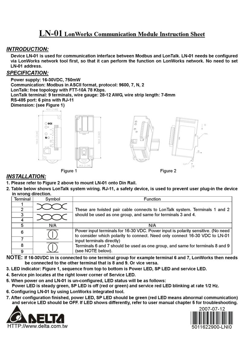
Delta Electronics
Delta Electronics LonWorks Communication Module LN-01 instruction sheet
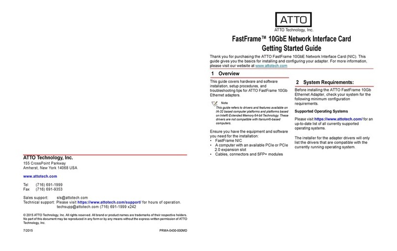
ATTO Technology
ATTO Technology FastFrame NS11 Getting started guide
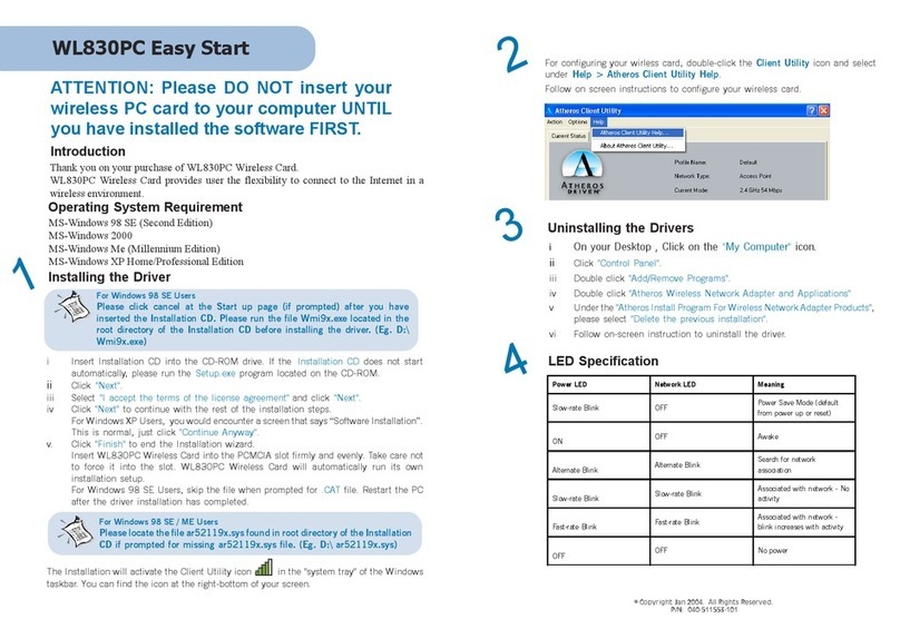
Aztech
Aztech WL830PC Easy start
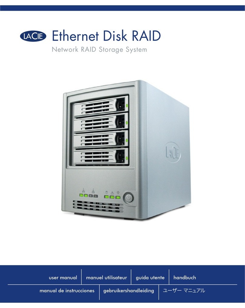
LaCie
LaCie Network Raid Storage System user manual
