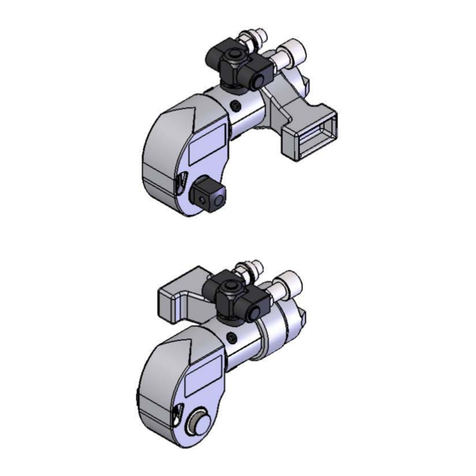
Bolttech-Mannings TorqLinks Manual

Revision No.: 20 Revision Date 8/14/2014
Page 1of 49
Bolttech Mannings Inc.
501 Mosside Blvd.
North Versailles, PA 15137 USA
Phone: 724-872-4873
www.bolttechmannings.com

Revision No.: 20 Revision Date 8/14/2014
Page 2of 49
INDEX Page
1. General Information………………………………………………….. 3
2. Connecting the System……………………………………………… 3
3. Safety Precautions…………………………………………………… 4
4. Setting Torque……………………………………………………….. 5
5. Applying the Torque Wrench……………………………………….. 5
6. Operating the Wrench System…………………………………….. 6
7. Loosening Procedures……………………………………………… 6
8. Preventative Maintenance………………………………………….. 7
9. Assembly Instructions and Parts Breakdown…………………….. 8-25
10. Parts List……………………………………………………………... 26-46
11. Torque Specifications………………………………………………. 47
11. Revision History………………………………………………………. 48

Revision No.: 20 Revision Date 8/14/2014
Page 3of 49
OPERATIONS / MAINTENANCE MANUAL
GENERAL
All Bolttech-Mannings Hydraulic Wrenches are supplied completely assembled,
ready for use. A Hydraulic Power Pack is required to provide the speed and
pressure that makes your Wrench System efficient and accurate.
CONNECTING THE SYSTEM
The wrench head and power pack are connected by a 10,000 psi hose assembly
which consists of two hoses. One hose has a female connector on each end
while the other has male connectors. Connect the twin line hose to the wrench
head and pump. Insure the connectors are fully engaged and screwed snugly
and completely together.

Revision No.: 20 Revision Date 8/14/2014
Page 4of 49
SAFETY PRECAUTIONS
Your Bolttech-Mannings torque wrench is a power tool, and as with any power
tool, certain safety precautions should be observed to avoid accidents or
personal injury. The following tips will assist you:
Do not kink the hydraulic hoses, and be sure they’re clear of any possible
reaction surface during operation.
Do not use the hoses or any hydraulic connection as a “handle”
All Torq links have an integrated reaction bar. The reaction bar should be
located on a solid, secure reaction point. For added safety, remain clear of
the reaction bar during operation. Also, when initially applying the tool,
pressurize the system momentarily; if the tool tends to “ride up” or “creep”,
stop and re-adjust the reaction bar to a more solid and secure position.
In most cases, the tool will allow “hands-free” operation. If the tool must be
held or steadied during operation, avoid handling the area around the
reaction bar.
Electric pumps should never be used in any atmosphere which could be
considered potentially volatile. If there is any doubt, use an air pump.
WHEN OPERATING OR ASSEMBLING EQUIPMENT, BE SURE TO ALWAYS
WEAR THE NECESSARY SAFETY PERSONAL PROTECTIVE EQUIPMENT
AS FOLLOWS:
Safety glasses
Protective leather gloves
Hard toe safety shoes
Protective FR garments or torso protective clothing
Hearing protection – ear plugs
Head protection – as required per the safety hazards present
At Bolttech-Mannings, safety is one of our primary concerns. By following these
few, simple precautions, you’ll be sure to obtain the most beneficial use of your
Bolttech-Mannings wrench system in the safest manner possible.

Revision No.: 20 Revision Date 8/14/2014
Page 5of 49
SETTING TORQUE
With the system fully connected and the proper power supply available, refer to
the certificate of calibration for the particular model and Serial number of the tool.
Verify that the test date is within the previous 12 months. Read across to the
corresponding pressure. This pressure is to be set on the pump. To do so, turn
on the pump, press down on the “advance” remote control button and hold;
pressure will build up on the gauge. To adjust pressure, loosen the locking ring
on the pressure regulator valve and turn the thumbscrew clockwise to increase
pressure, counterclockwise to decrease pressure.
NOTE: When decreasing pressure, it is necessary to turn the thumb-screw
to a pressure setting BELOW what is desired and gradually
increase the pressure to the desired level.
Once the desired pressure is stabilized, re tighten the locking ring.
PRIOR TO BEGINNING TO TORQUE – PRESS DOWN THE EXTEND BUTTON
ON REMOTE CONTROL AND CONFIRM THE CORRECT PRESSURE HAS
BEEN SET.
APPLYING THE TORQUE WRENCH
Place the tool on the nut making sure the tool has fully engaged the nut.
Make sure the reaction bar is firmly abutted against a stationary object (i.e. an
adjacent nut, flange, equipment housing, etc.)
Make sure that the hoses are not placed between the reaction members.
Apply momentary pressure to the system to ensure proper tool placement.

Revision No.: 20 Revision Date 8/14/2014
Page 6of 49
OPERATING THE WRENCH SYSTEM
By depressing the extend button on the remote control, the rear of the tool will be
pushed back until its reaction bar contacts its reaction member. Continue to hold
down the button as the socket turns pressure builds very rapidly to signify
that the hydraulic cylinder inside the tool is fully extended and will not turn
the nut any further. The rapid buildup of pressure should be to the point of
where the pressure was preset prior to applying the wrench.
IMPORTANT: This rapid buildup of pressure does not indicate that this
pressure (torque) is being applied to the fastener. It only
indicates that the cylinder is fully extended and can not turn the
socket further until the tool is retracted to pick up the next tooth
on the ratchet wheel.
Depressing the retract button on the remote control will retract the cylinder, the
tool will reset itself and the operator will hear a few audible “clicks” indicating he
can again push the remote control button and the socket will turn. Each time the
cylinder is extended and retracted, it is called a cycle. Successive cycles are
made until the tool “stalls” at the pre set pressure (torque).
NOTE: Always attempt one final cycle to insure the “stall” point has been
reached.
LOOSENING PROCEDURES
First, set the pump at the maximum pressure the tool can be used. Flip the tool
over so that it will loosen and apply the tool, assuring the reaction bar abuts
squarely off a solid reaction point. Press and hold the remote control button.
Pressure will build up as the socket begins to turn. Cycle the wrench until the
fastener is loose enough to turn by hand.
If the socket does not turn using the above procedure, it is an indication that you
will require the next larger size tool to loosen the fastener.

Revision No.: 20 Revision Date 8/14/2014
Page 7of 49
PREVENTATIVE MAINTENANCE
Tool failure does occur. Such failure is most often in the hydraulic connectors or
hoses. These items are repairable/replaceable immediately, since they are
available universally. Failures of structural members of the tool are quite rare, but
replacement parts are available from stock.
Special tools are required for the disassembly of the hydraulic cylinder and drive
mechanism.
LUBRICATION: Tool should be lubricated annually under guidelines
detailed in this manual. Under harsh environmental conditions, cleaning
and lubricating should be done more frequently.
HYDRAULIC HOSES: Hoses should be checked for cracks and leaks
after each job. Hydraulic fittings can become plugged with dirt and should
be flushed periodically.
QUICK-CONNECTS: Fittings should be kept clean and not allowed to be
dragged along the ground or floor, as even small particles of dirt can
cause internal valves to malfunction. External leakage can be eliminated
by applying a fresh coat of good quality sealant to the threads and
tightening securely.
Before and after each use the user should check tightness of swivel
connection. By hand, grab the swivel by the fittings and work the swivel
back and forth to make sure there is no play in the swivel base. Swivel
base cap screws should be tight enough to eliminate any play in the swivel
assembly base connection. If there is any play in the swivel base, do not
use and service prior to use.

Revision No.: 20 Revision Date 8/14/2014
Page 8of 49
SPRINGS: Springs are used for the drive pawl assembly and ratchet
device. These springs should be checked twice a year and replaced, if
necessary.
HYDRAULIC SEALS: If the cylinder seals should require replacement
because of leaks, it is recommended that all other seals and o-rings be
replaced at the same time. Seal Kits are readily available. It is
recommended that seals be replaced annually. Heavy use may dictate
that the seals be replaced more often.
MACHINE PARTS: All components that are included on the tool should be
inspected once a year to determine if there are any cracks, chips, or
deformities. If so, immediate replacement is required.

Revision No.: 20 Revision Date 8/14/2014
Page 9of 49

Revision No.: 20 Revision Date 8/14/2014
Page 10 of 49

Revision No.: 20 Revision Date 8/14/2014
Page 11 of 49

Revision No.: 20 Revision Date 8/14/2014
Page 12 of 49

Revision No.: 20 Revision Date 8/14/2014
Page 13 of 49

Revision No.: 20 Revision Date 8/14/2014
Page 14 of 49

Revision No.: 20 Revision Date 8/14/2014
Page 15 of 49

Revision No.: 20 Revision Date 8/14/2014
Page 16 of 49

Revision No.: 20 Revision Date 8/14/2014
Page 17 of 49

Revision No.: 20 Revision Date 8/14/2014
Page 18 of 49

Revision No.: 20 Revision Date 8/14/2014
Page 19 of 49

Revision No.: 20 Revision Date 8/14/2014
Page 20 of 49
Table of contents
Other Bolttech-Mannings Power Tools manuals
Popular Power Tools manuals by other brands
Berner
Berner BWC 35 Original instructions
Altrad
Altrad Belle PCX 60A Operator's manual
Westfalia
Westfalia GW2000E instruction manual

SUHNER ABRASIVE
SUHNER ABRASIVE LLC 4-TOP Technical document
Matatakitoyo Torque Tools
Matatakitoyo Torque Tools INS-25N Operation manual
Roller
Roller Mini-Ortem A instruction manual
ISC
ISC Singing Tree Rigging Rope Wrench General Instructions for Use
kincrome
kincrome KP15001 quick start guide

Black & Decker
Black & Decker PLATE JOINER 3382 instruction manual
stayer
stayer PR10EK operating instructions

Milwaukee
Milwaukee M12 FID2 Original instructions
Hardinge
Hardinge SERIES I Installation operation & maintenance
