Hardinge SERIES I Owner's manual
INSTALLATION, OPERATION,
MAINTENANCE, AND PARTS LIST
SERIES I
MILLING MACHINES
Revised: August 29, 2005
Manual No. M-450 Litho in U.S.A.
Part No. M -0009500-0450 June, 2003
TP5260

CHAPTER 2 - OPERATION
HEAD CONTROLS
M-450 2-1
Figure 2.1 - Head Controls Parts Assembly
A
N
O
P
Q
R
C
B
M
G
E
D
F
H
I
J
K
L
TP5285

HIGH-LOW RANGE SWITCH
High-Low Range Switch “A”, Figure 2.2, is a
motor reversing switch. When the attachment is in
direct drive (HIGH SPEED), the motor and spindle
are turning in a clockwise direction as viewed from
the top of machine. When the attachment is in “Back
Gear”(LOWSPEED),thespindlewillrunbackwards
(counter-clockwise) unless the motor direction is
reversed by moving switch to “Low”.
The back gear lever is marked Hi-Lo. This will
indicate the proper switch position. They should be
positioned alike or the spindle will run backwards.
- NOTE -
Spindle should run in clockwise position.
VARIABLE SPEED DIAL
Variable Speed Dial “B”, Figure 2.3, visibly indicates, in windows, the speed range that the
machine is operating in, 60 to 500 low range, 500 to 4200 high range.
2-2 M-450
Figure 2.2 - High-Low Range Switch
A
TP5286
Figure 2.3 - Variable Speed Dial
TP5287
B

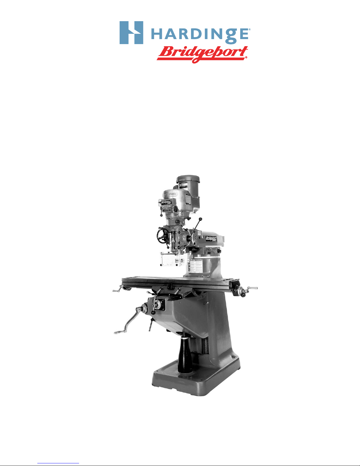
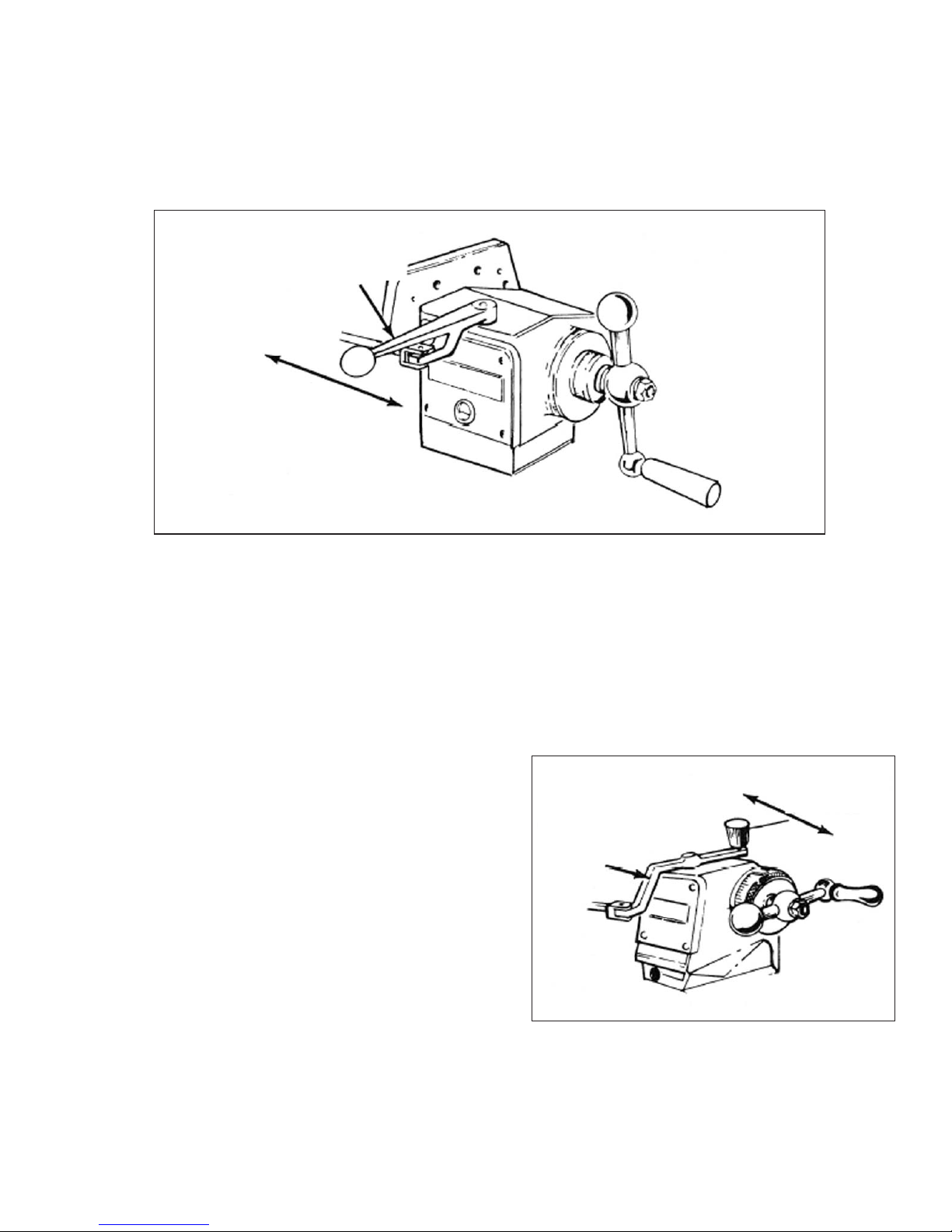
SPINDLE BRAKE
Spindle Brake “C”, Figure 2.4, can be moved in
either direction to stop spindle; however, when
locking spindle, brake lever should be moved either
by pulling towards the operator or pushing away
from the operator, then raised. When brake is worn
out it has to be replaced. There are no adjustments
to be made.
- CAUTION -
BE certain that spindle brake is re-
leased before starting the motor.
This is important as the motor can
be damaged if switch is turned on
with brake in locked position.
QUILL FEED SELECTOR
The Quill Feed Selector “D”, Figure 2.5, is used
for selecting the three feeds: .0015”, .003” and .006”
per revolution. It is shifted by pulling knob out and
turning from one position to the other. Feeds are
stamped on cover below indentation hole. Feed is
more readily engaged when spindle is running.
M-450 2-3
Figure 2.4 - Spindle Brake
Lock On
Lock Off
TP5288
C
Figure 2.5 - Quill Feed Selector
D
TP5289

QUILL STOP KNOB
Quill Stop Knob “E”, Figure 2.6, is used to
disengage automatic feed in either direction as well
as the stop point setting working depths.
MICROMETER NUT
Micrometer Nut “F”, Figure 2.6, is used for setting
depths. Each graduation on nut indicates .001” of
depth, it reads directly to scale mounted along the
side of it. Depths may be obtained by setting
micrometer nut in conjunction with quill stop.
FEED REVERSE KNOB
The position of the Feed Reverse Knob “G”,
Figure 2.7, depends upon direction of spindle
rotation. If boring with right hand cutting tools, pull
feed handle towards operator until clutch becomes
engaged.
Neutral position is between forward and reverse
position. It is recommended that the handle be left in
neutral position when not in use.
MANUAL FEED HANDWHEEL
Feed Reverse Knob “G” should be in neutral
position and Feed Control Lever “I”, Figure 2.8
engaged. Clockwise rotation of Manual Feed
Handwheel “H”, Figure 2.7, moves quill down. The
manual feed handwheel and the quill feed handle
may be disengaged by moving them outward about
.125”.
2-4 M-450
Figure 2.6 - Quill Stop Knob and
Micrometer Nut
E
F
TP5290
Figure 2.7 - Feed Reverse Knob and
Manual Feed Handwheel
Neutral
G
Down
TP5291
Up
H
FEED CONTROL LEVER
Feed Control Lever “I”, Figure 2.8, engages
overload clutch on pinion shaft when positioned left
and will stay engaged until either quill stop comes in
contact with micrometer adjusting nut, forcing feed
control lever to drop out automatically, or release
manually by engaging lever to right.
FEED CONTROL OVERLOAD CLUTCH
The Feed Control Overload Clutch is set at the
factory to hold up to 200 lbs of down pressure on
quill, which will accommodate drills up to .375”
diameter in mild tool steel.
- CAUTION -
This clutch should not be tampered
with in the field.
- NOTE -
The feed control lever must be en-
gaged in order to use manual feed
controls. the quill feed handle and
manual feed handwheel may be
removed when not in use.
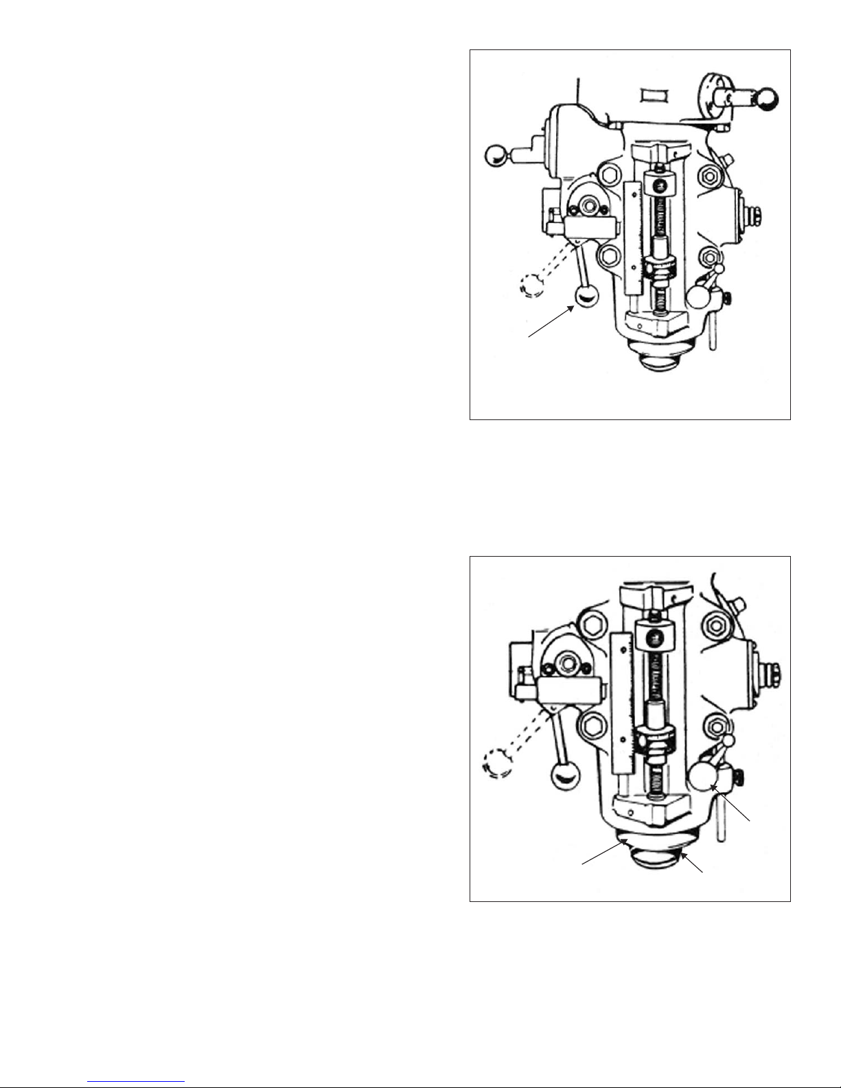
QUILL
Quill “J”, Figure 2.9, contains the spindle
assembly and can be raised or lowered by using the
quill feed handle “M”, Figure 2.10.
SPINDLE
Spindle “K”, Figure 2.9, performs the actual
rotation and also retains the machine tooling.
QUILL LOCK
Quill Lock “L”, Figure 2.9, is a friction lock for use
when quill is in a stationary position such as a milling
operation. It is recommended that this lock be used
whenever quill movement is not desired.
M-450 2-5
Figure 2.8 - Feed Control Lever and
Feed Control Overload Clutch
I
Engage
Disengage
TP5292
Figure 2.9 - Quill, Spindle and
Quill Lock
J
L
TP5293
K
QUILL FEED HANDLE
Quill Feed Handle “M”, Figure 2.10, is used to
raise and lower the quill manually. It is generally
recommended that handle be engaged when using
the power feed. It may be removed by simply pulling
handle off.
POWER FEED TRANSMISSION ENGAGEMENT
CRANK
Power Feed Transmission Engagement Crank
“N”, Figure 2.11, engages power feed worm gear.
When lever is in right hand hole, the power feed
worm gear is engaged.
To engage worm gear, pull knob out and crank
handle in clockwise or down direction and move to
opposite position (see Figure 2.12).
- NOTE -
Crank should be rotated counter-clock-
wise to engage power quill feed. Crank
should be rotated clockwise to disen-
gage.
- CAUTION -
Power feed worm gear may be en-
gaged when spindle is rotating,
however, it should be engaged
gently to avoid damage to worm
gear. The worm gear may be disen-
gaged at any time. do not use power
feed at speeds above 3000 RPM.
2-6 M-450
Figure 2.10 - Quill Feed Handle
M
TP5294
Figure 2.11 - Power Feed Transmission
Engagement Crank
N
TP5295
Figure 2.12 - Worm Gear Disengagement
Disengaged Engaged
Clockwise Counter-
Clockwise
TP5296

HI-NEUTRAL-LO LEVER
The Hi-Neutral-Lo Lever “O”, Figure 2.13, is used to put the attachment into either back gear or
direct drive. Rotate the spindle by hand to facilitate meshing of clutch or gears.
Neutral is provided to permit free spindle rotation for indicating and setup work.
In the high speed position (direct drive) the spindle is driven by tapered clutch teeth. If the clutch is
not meshed tightly, clutch rattle will be heard. This can be corrected by loosening the two securing
screws in lever while in high speed position. The clutch spring will automatically adjust the clutch.
Tighten the two securing crews in lever.
- CAUTION -
Do not shift hi-lo lever while motor is running.
M-450 2-7
Figure 2.13 - Hi-Neutral-Lo Lever
Neutral
High Low
Securing Screws
TP5297
O

SPEED CHANGE HANDWHEEL
- CAUTION -
DO NOT attempt to change spindle RPM unless the motor is running. Dial
speeds will only be approximate. Belt wear will cause a slight variation in
speeds from what is indicated on the dial.
Spindlespeedsareadjustedby turningSpeedChange Handwheel“P”,Figure 2.14,onthe frontof
the belt housing. There are two ranges: 60 to 500 and 500 to 4200.
To obtain 60 to 500 (low range):
1. Hold the Hi-Neutral-Lo lever (right rear
side of the attachment) so the gears are
clear of one another.
2. rotate the spindle nose by hand until the
gears line up, then move the Hi-Neu-
tral-Lo lever to the “Lo” position (back
gear).
3. Use the low range on the drum switch to
engage the back gears.
- CAUTION -
If the back gears do not mesh, do
not force the lever.
To obtain 500 to 4200 (high range):
1. Hold the Hi-Neutral-Lo lever (right rear
side of the attachment) so the gears are
clear of one another.
2. rotate the spindle nose by hand until the
gears line up, then move the Hi-Neu-
tral-Lo lever to the “Hi” position.
3. Set the drum switch to high range.
- CAUTION -
Try to avoid shifting the hi-lo lever when the feed worm is engaged.
2-8 M-450
Figure 2.14 - Speed Change Handwheel
- CAUTION -
Do Not Move
Unless Motor is
Running
Increase
Speed Decrease
Speed
P
TP5298
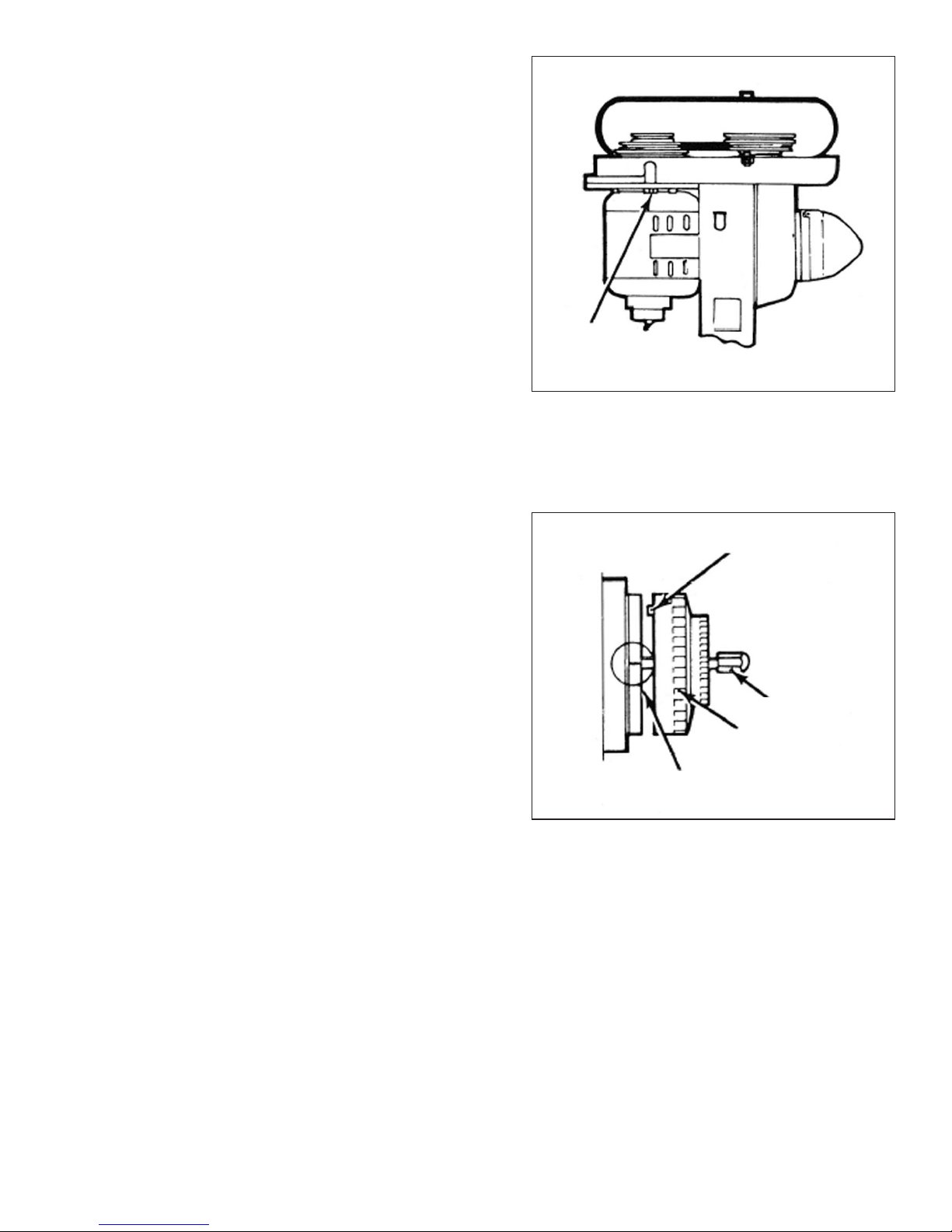
MOTOR
Motor “Q”, Figure 2.15, has the following specifications:
•2 HP variable speed (with 2J head)
•3 HP 30 minute duty rate
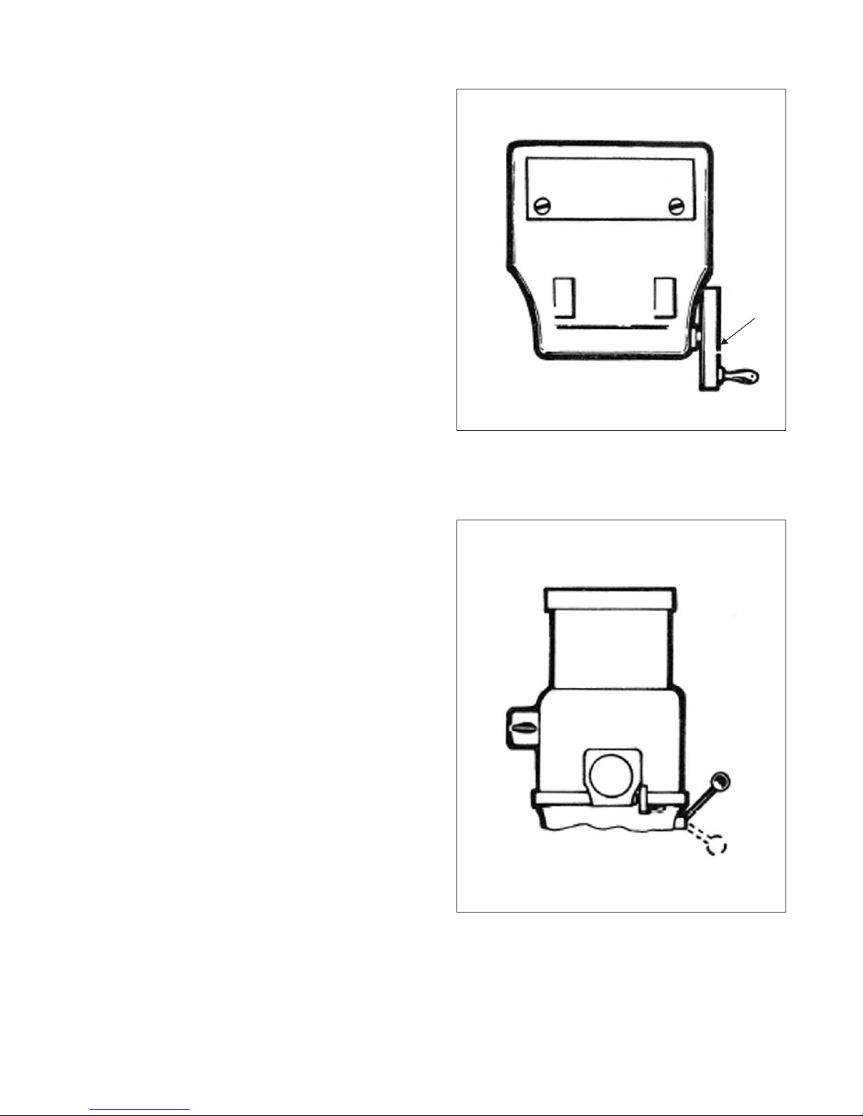
DRAWBAR
When tightening or loosening the Drawbar “R”, Figure 2.15, it is necessary to lock the spindle. To
accomplish this, use the spindle brake which is located on the left side of the belt housing, pulling
towardstheoperator orpushingawayfromtheoperatoruntil itbinds,thenraisethequillfeed handle.
Drawbar has 7/16”-20 right hand thread and should be tightened by hand with normal amount of
pressure using wrench furnished with machine. To loosen collet, back off drawbar and if collet does
not open immediately, give knob on top of drawbar a slight tap. Spindle has non-sticking taper and
collet should release readily.
M-450 2-9
Figure 2.15 - Motor and Drawbar
TP5299
Q
R
OPERATIONAL PROCEDURES
Spindle Speed
- CAUTION -
DO NOT change speed when spin-
dle is stationary. Change speed only
when spindle is running.
To change speed within range:
1. Start spindle.
2. Turn handwheel “A”, Figure 2.16, to select
required speed.
Back Gear (Low Speed)
- CAUTION -
DO NOT change range while spindle
is running. Change range only when
spindle is stationary.
To change range from direct to back gear drive:
1. Switch “B”, Figure 2.17, to OFF (Stop spindle
rotation).
2. Move lever “C” through neutral to LOW (This
reverses the spindle rotation).
3. Switch “B” to LOW.
2-10 M-450
Figure 2.16 - Spindle Speed Change
A
TP5300
Figure 2.17 - Back Gear Range Change
C
B
TP5301

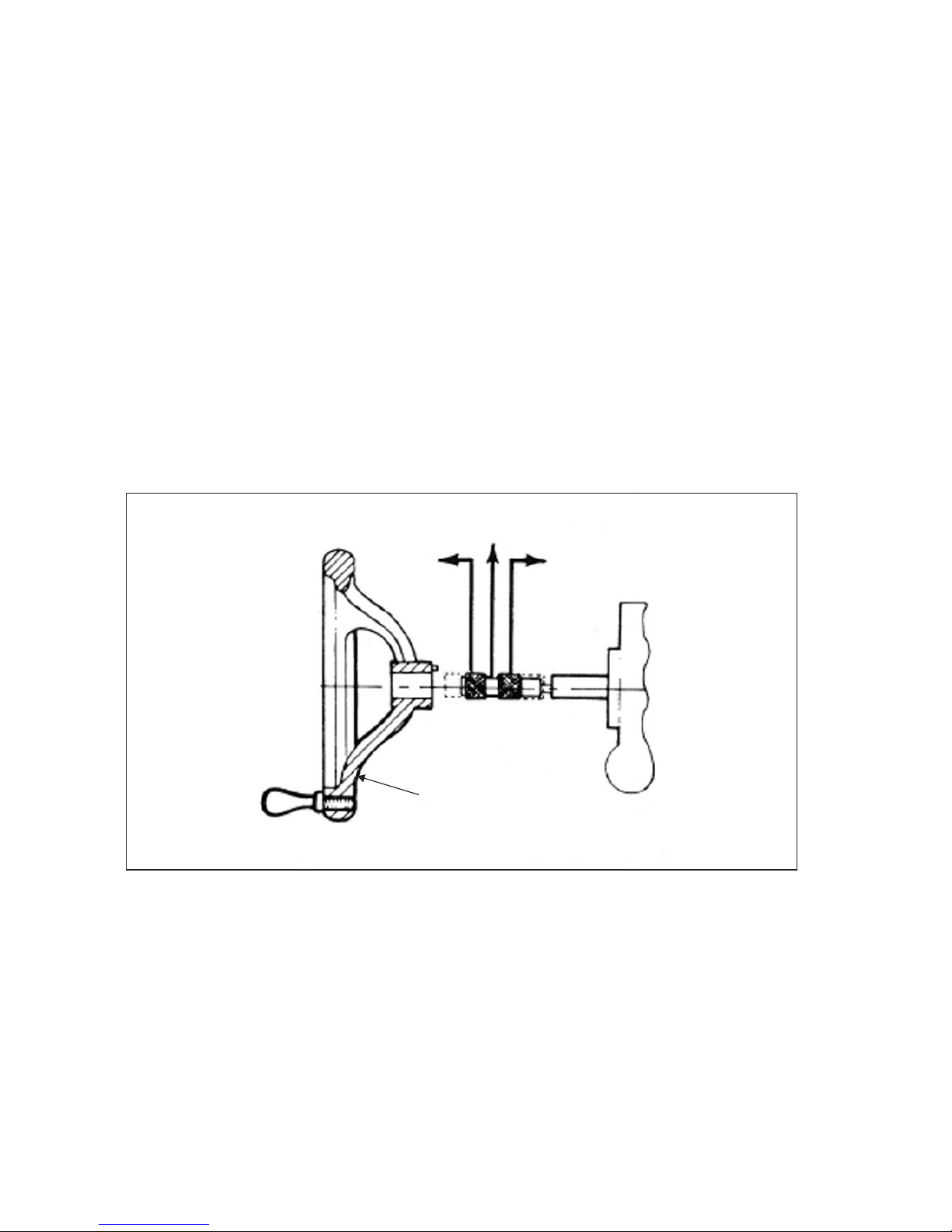
Direct Drive (High Speed)
To change range from back gear to direct drive:
1. Switch “B” to OFF (Stop spindle rotation).
2. Move lever “C”, Figure 2.18, through neutral
to HIGH.
3. Rotate spindle by hand until the clutches are
felt to engage.
4. Switch “B” to HIGH.
Quill Feed
FINE HAND FEED
1. Disengage Auto Quill Feed “D”, Figure 2.19.
2. Locate “F” in mid (neutral) position.
3. The quill is now under handwheel control
M-450 2-11
Figure 2.18 - Direct Drive Lever
High
C
Neutral Low
TP5302
Figure 2.19 - Quill Feed
Fine Hand Feed Control
E
F
I
D
H
G
Off
On
Engage
TP5303
AUTOMATIC FEED
- NOTE -
Maximum loading .375” (9.5mm) diameter drill steel.
1. Ensure quill lock “G”, is off.
2. Set micrometer dial “H” to required depth.
3. Engage auto quill feed “D” when motor has stopped
4. Select feed rate “I”.
5. Select feed direction “F”, Figure 2.22.
6. Engage feed trip lever “E”. The feed will automatically trip out at a depth within .010”
(.25mm)
7. Hand feed to dead stop for repeating accuracy .001” (.025mm)
- CAUTION -
Do not engage quill feed “D” over 3000 RPM.
2-12 M-450
Figure 2.20 - Quill Feed
Automatic Feed Control
F
Up
Neutral
Down
Fine Feed
Handwheel Engage
TP5304

HEAD
OPERATIONAL PROCEDURES
Spindle Brake
Brake lever has capability to rotate in either
direction to brake and lock.
1. CAM upwards to lock and prevent movement
of spindle (see Figure 2.21).
Quill Sensitive Hand Feed
1. Place the handle on the quill feed shaft.
2. Select the most suitable position.
3. Push home until the locating pin engages.
M-450 2-13
Figure 2.21 - Spindle Brake
Brake
Brake
Off
Turn and
Lift to
Lock
TP5306
Figure 2.22 - Quill Sensitive Hand Feed
TP5307
MACHINE
OPERATIONAL PROCEDURES
Swivel Belt Housing
- CAUTION -
Incorrect spline alignment can be
caused by unequal tightening of the
locknuts ’J’ causing fluctuation of
the quill feed which can be felt
through the sensitive feed handle. It
is advised to call Hardinge service
department before attempting this
procedure.
1. Loosen three locknuts “J”, Figure 2.23.
- WARNING -
DO NOT remove these locking nuts.
2. Swivel to required angular setting.
3. Tighten three locknuts “J” snugly before final
tightening of locknuts. Run spindle to give
correct spline alignment, then tighten lock-
nuts securely.
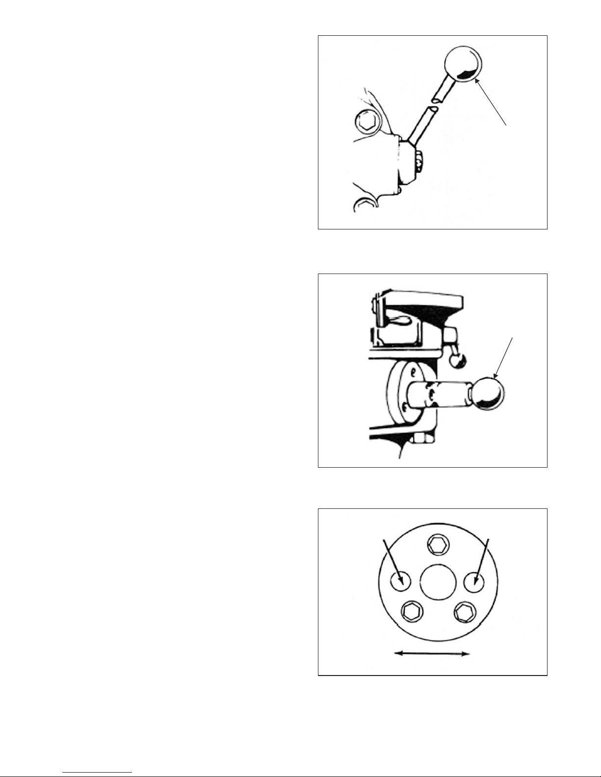
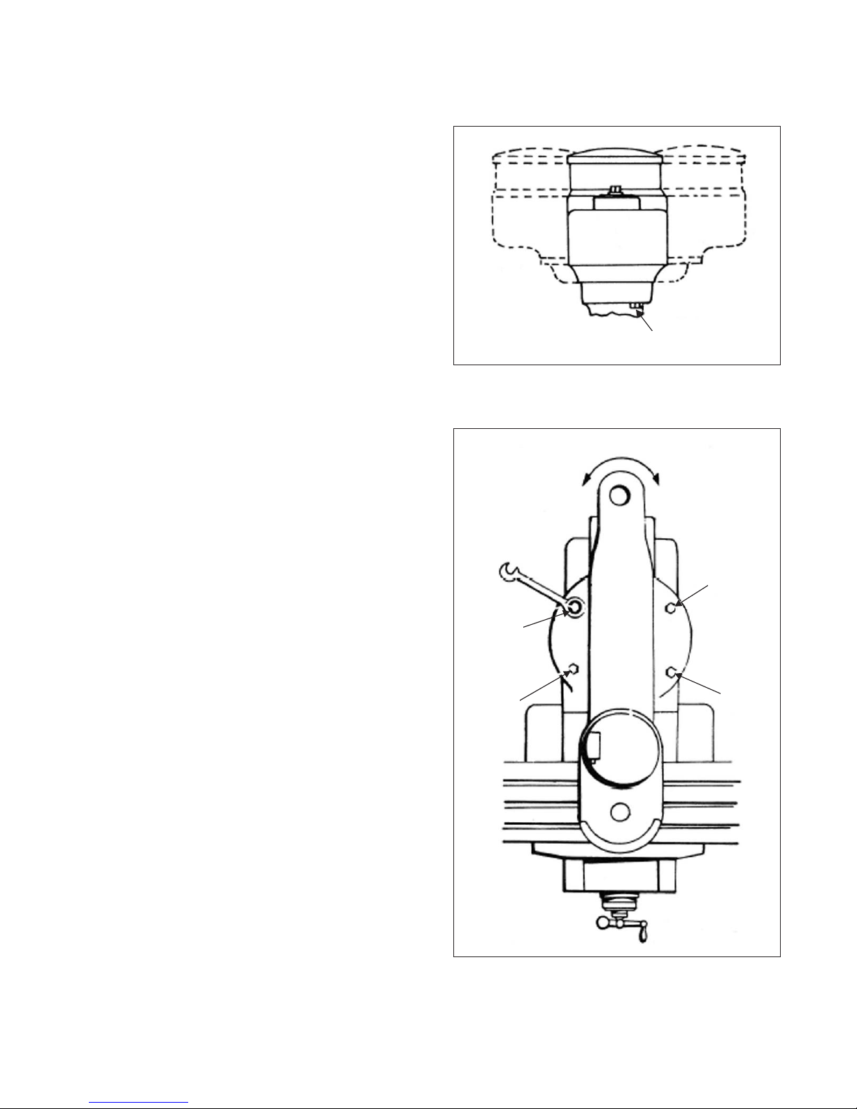
Swivel Turret
1. Use wrench supplied with machine to loosen
the four bolts “K”, Figure 2.24.
- WARNING -
DO NOT remove these four bolts.
2. Index to the required setting.
3. Lock the four bolts “K” to 47 lb-ft.
2-14 M-450
Figure 2.23 - Swivel Belt Housing
TP5305
J
Figure 2.24 - Swivel Turret
360°
K
KK
K
TP5308
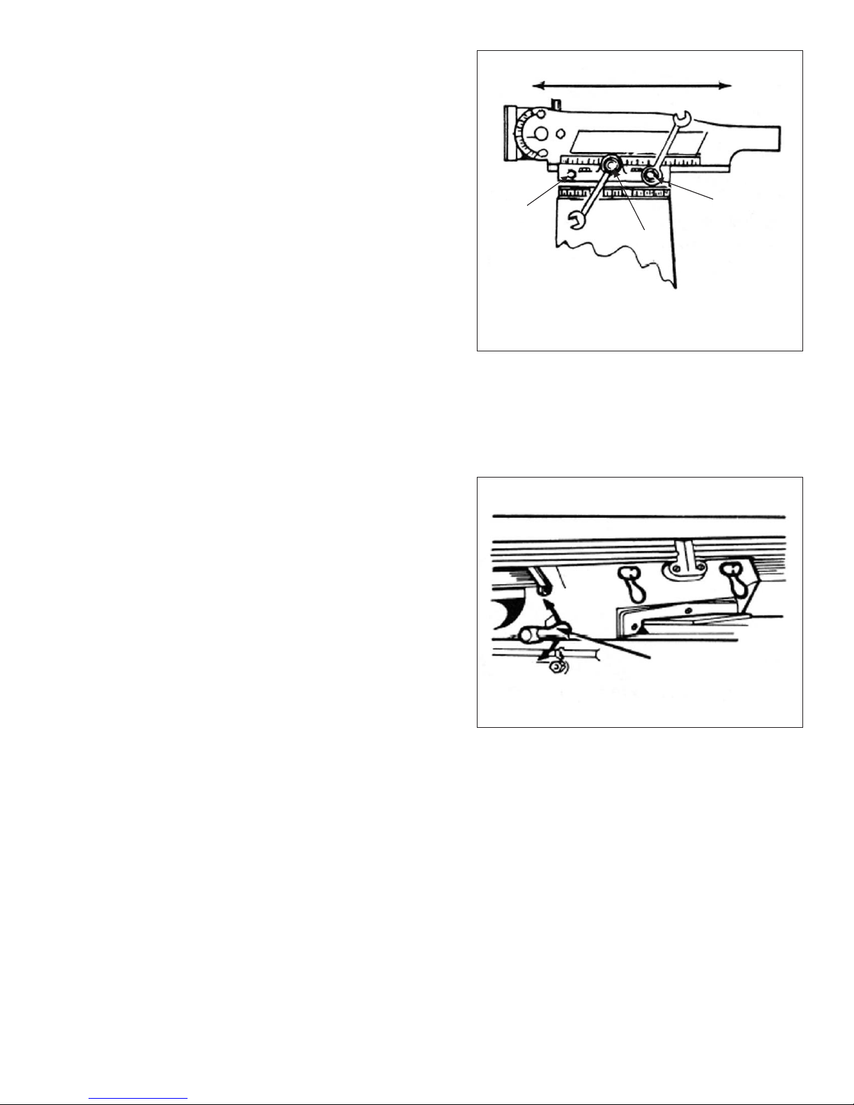
Move Ram Slide
1. Use wrench provided with machine to loosen
bolts “L” and “M”, Figure 2.25.
2. Use wrench to move the slide to the desired
position using bolt “N”.
3. Tighten bolts “L” and “M”, starting with the
rear bolt.
- NOTE -
It is recommended that on heavy mill-
ing work, head should be kept as close
to column as possible, where maxi-
mum rigidity is obtained.
Saddle Clamping
When milling with longitudinal table feed only, it is
advisable to clamp the knee to the column (see
Figure 2.27) and the saddle to the knee to add
rigidity to these members and provide for heavier
cuts with a minimum of vibration. The saddle locking
lever is located on the left hand side of the saddle.
Excessive moisture can cause slight table bind.
Use moderate clamping pressure, as this will hold
saddle sufficiently.
M-450 2-15
Figure 2.25 - Ram Slide
TP5309
L
N
M
Rear
Figure 2.26 - Saddle Clamping
TP5310
Unlock
Lock
Saddle
Locking Lever

Table Clamping
The table clamp levers are located on front of
saddle and should always be clamped when
longitudinal movement is not required (see Figure
2.28).
Knee Clamping
The knee clamping levers are at the left side of the knee and front of knee. Leave clamped at all
times unless using knee in operation (see Figure 2.27).
2-16 M-450
Figure 2.27 - Knee Clamping
Knee
Clamp
On Off
Clamp
Knee
Clamp
Off
On
TP5312
Figure 2.28 - Table Clamping
Unlock
Lock
Table Clamp
Levers TP5311
POWER FEED CONTROLS
OPERATIONAL PROCEDURES
Variable Table Feeds
Power Feed (X-Axis) Table
Quick-Release Safety Handle
Grip handle and turn to either left or right until spring loaded plunger engages in position.
- NOTE -
Ball crank handle is a safety device. Do not tamper with this assembly.
Variable Cross Slide Feed
Cross Feed Power Feed (Y-Axis)
M-450 2-17
Figure 2.29 - Variable Table Feeds
Feed Engage
Lever
TP5313
Feed Left
Feed Right
Neutral
Figure 2.30 - Variable Cross Slide Feed
TP5314
Neutral
In
Out
Cross Feed
Engage Lever

E-HEAD CONTROLS
OPERATIONAL PROCEDURES
Head Swivel
1. Loosen the four locknuts (see Figure 2.32). Support unit to prevent free fall.
2. Swivel to required angular setting.
3. Tighten the four locknuts first to 25 lb-ft. Then 50 lb-ft (ref. Page 1-4).
- NOTE -
Remove the screw sealing vent hole before operating machine (ref. Page 3-15).
2-18 M-450
Figure 2.31 - Shaping Head
(Guard Removed for Clarity)
Motor
Locking
Nuts
Stroke
Adjustment
locknut
On/Off
Switch
Tool Holder
Clapper Box
TP5315
Figure 2.32 - Shaping Head
(Guard Installed)
TP5316
Locknuts
To Change Speed
1. Disconnect power from head.
2. Loosen the two motor locknuts (see Figure
2.33).
3. Slide motor forward.
4. Position vee belt on appropriate pulleys.
5. Slide motor to rear to tension vee belt.
6. Tighten the two motor locknuts.
With 50 cycle 1425 rpm 60, 85, 120, 170, 245 350
strokes per minute.
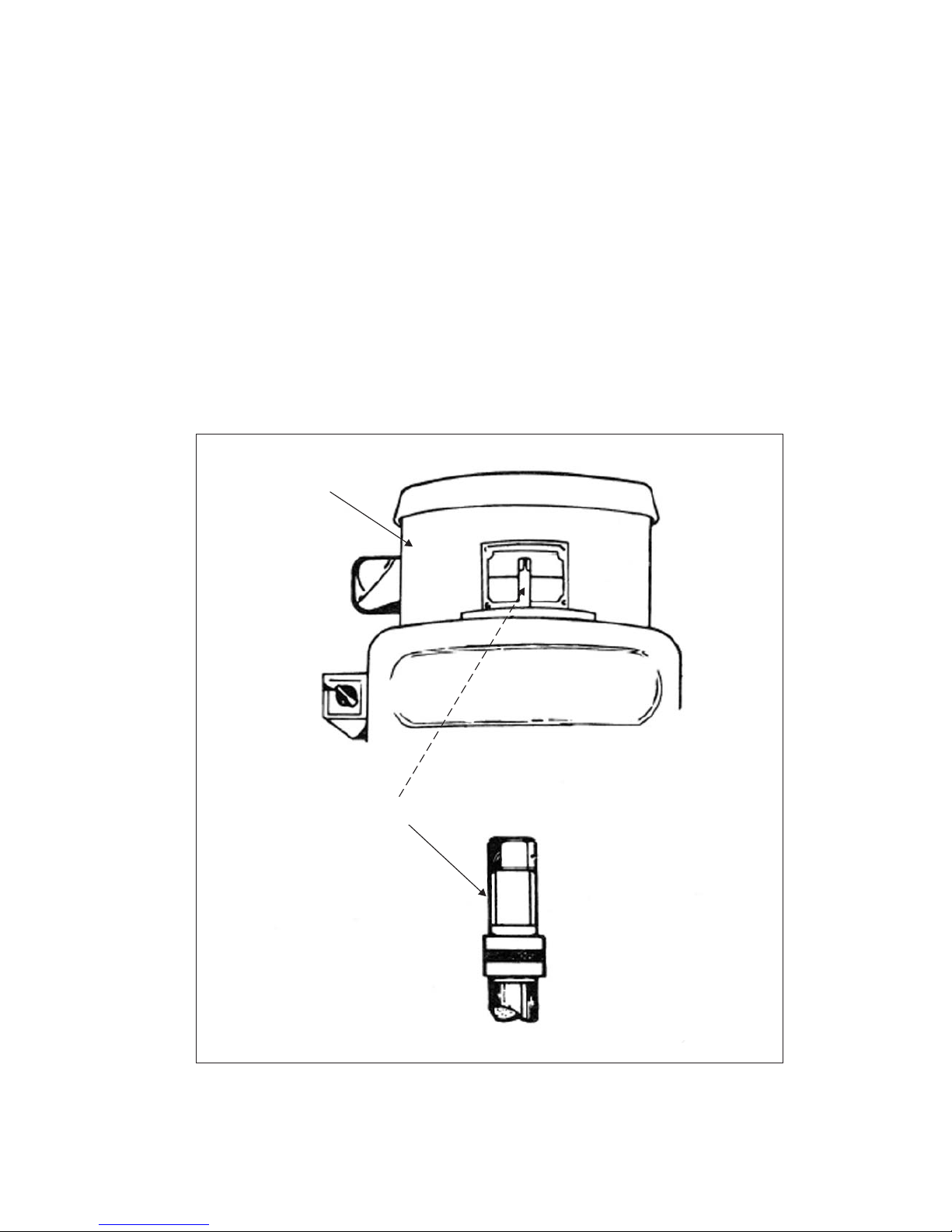
To Change Stroke
1. Loosen locknut (see Figure 2.34).
2. Turn stroke dial to required setting.
3. Press dial home to engage pin.
4. Tighten locknut.
- NOTE -
Before operating attachment, ensure
locknut is tight.
M-450 2-19
Figure 2.33 - Changing E-Head Speed
Locknuts
TP5317
Figure 2.34 - Changing E-Head Stroke
Engage Pin
Locknut
Stroke Dial
Setting Datum
TP5318
Table of contents
Other Hardinge Power Tools manuals


