Bolttech-Mannings TP30K-Z-DP User manual

BOLTTECH MANNINGS
TP30K-Z-DP
OWNERS MANUAL
10/10
BOLTTECH-MANNINGS Inc.
501 Mosside Blvd.
North Versailles, PA 15137 USA
Phone: 724-872-4873
www.bolttechmannings.com

BOLTTECH-MANNINGS
Installation and Maintenance Manual
TP30K-Z-DP Stud Tensioner Pump
Serial # _______________________
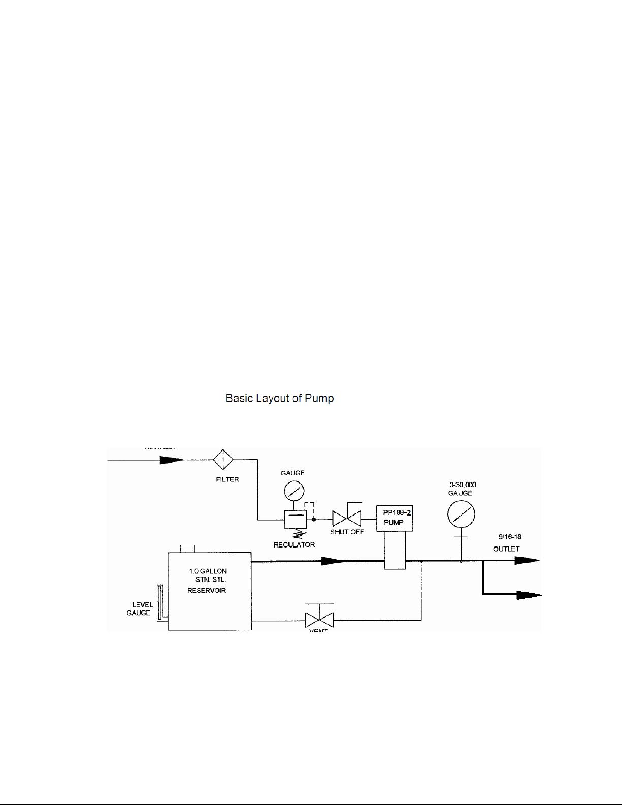
INTRODUCTION
The BOLTTECH-MANNINGS tensioning pump described in this manual is a pneumati-
cally operated, gate valve controlled piston pump similar in style to a dou-
ble-acting pneumatic cylinder.
TheTP30K-Z-DP pump has an area ratio of 440:1 between the pneumatic
piston and hydraulic plunger.
This relates to a maximum hydraulic output pressure that is 440 times
greater than the pneumatic drive pressure, e.g. With 50 psi air, the outlet
would be 22,000psi.
Do not use an air lubricator because the pump was lubricated with a sili-
con free grease when built. (Kluber Lube)
A compressed air filter is required and if the air is not dry, a water separa-
tor must be used.
The pumps are shipped from Bolttech-Mannings with an air filter and water separa-
tor installed.

INITIAL START UP
1) Fill the reservoir with 2 Gallons of Hydraulic Oil. (Mobile AW-46 or
equivalent)
2) Open the air regulator on top of unit, by turning the knob counter-
clockwise until it is loose.
3) Open the vent needle valve completely, by turning the handle counter-
clockwise.
4) Turn on the pump and run unit by holding toggle valve in “on” position
5) Close the air regulator on top of unit, by turning the knob clockwise until
you reach 20 psi.
6) Let the pump cycle slowly to prime itself. When a continuous stream of
fluid runs through the system and back into the reservoir, close the main
air shut-off ball valve.
7) Adjust the air regulator on top of unit, until desired air pressure is
achieved, as indicated on the air gauge and push in the handle to lock
in place.
The desired air drive pressure is a factor of the final fluid pressure and the
pressure ratio of the pump. The pump in this unit has a 440:1 pressure ratio.
The air drive pressure required would be the final fluid pressure desired, di-
vided by 440.
Pa = Po/440 Pa = Air drive pressure Po = Required Outlet pressure
The unit is now ready for operation
THE MAXIMUM PRESSURE RATING OF THE PUMP SYSTEM IS 25,000 PSI.
**NOTE: THE OUTLET PRESSURE SHOULD NEVER EXCEED 21,750 PSI,
THIS IS TO PREVENT OVER PRESSURIZATION OF THE TENSIONERS
WHICH COULD CAUSE DAMAGE OR PERSONAL INJURY.

Operating the System
Make sure that oil reservoir is full.
Air Shut off Valve should be in the off position.
Oil Return Valve should be open (turn counter clockwise)
Make sure air pressure regulator is set to desired pressure.
Attach hoses to Bolttech-Mannings Hydraulic Stud Tensioners.
Rotate and close Oil Return Valve to build hydraulic pressure (turn clockwise)
Turn on the pump and run unit by holding toggle valve in “on” position
When desired hydraulic pressure is reached rotate Air Shut Off Valve to the off
position.
To release hydraulic pressure, open the Oil Return Valve (turn counter clockwise)
MAINTENANCE
USEONLYORIGINALBOLTTECHMANNINGSSPAREPARTS
THEAIRDRIVESOFALLLIQUIDPUMPSAREFACTORYPRE‐TREATED
WITHSILICONFREEGREASE(KLUBERLUBE)ANDREQUIRENOFURTHER
LUBRICATIONEXCEPTDURINGROUTINEMAINTENANCE.

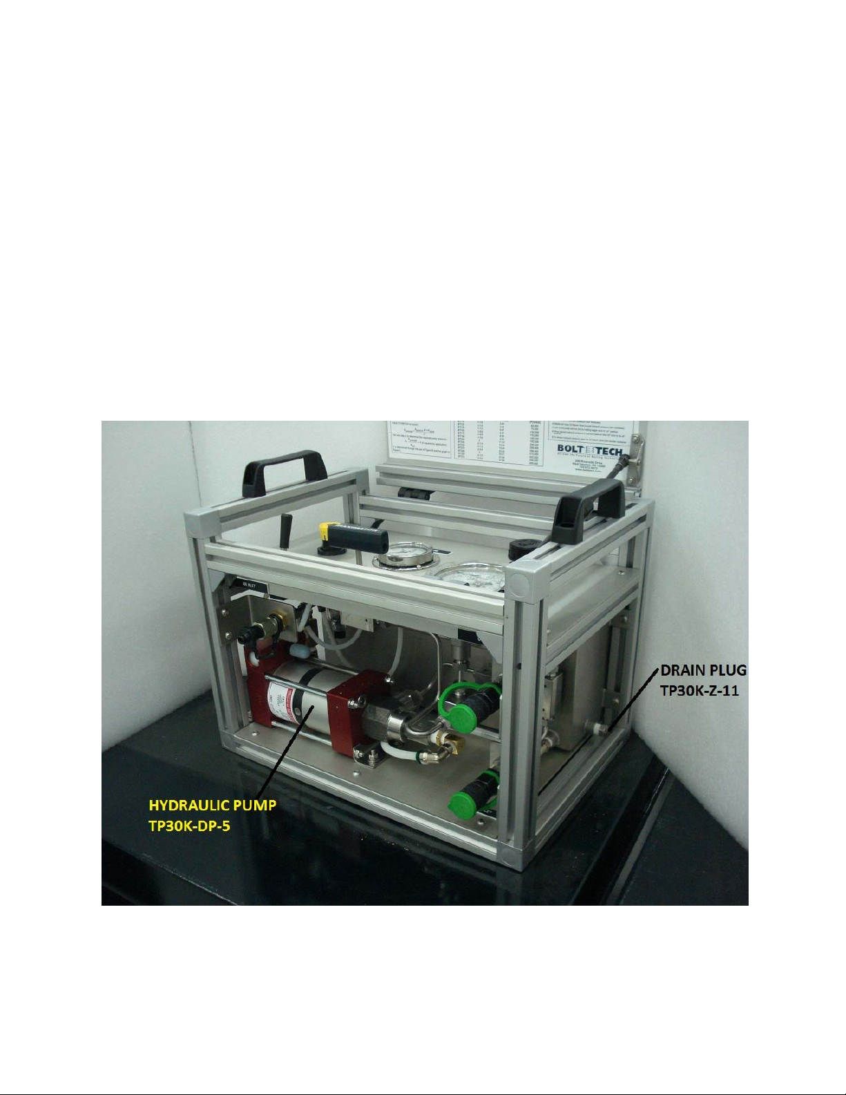
Parts List:
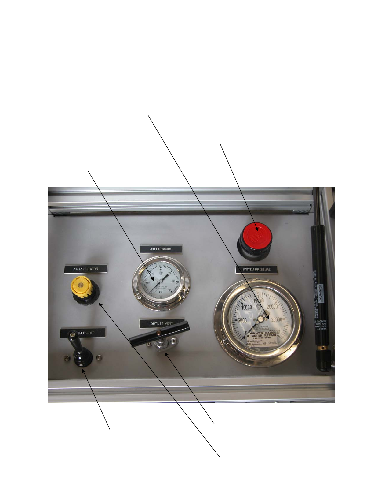
1 Air Pressure Regulator TP30K-Z-1
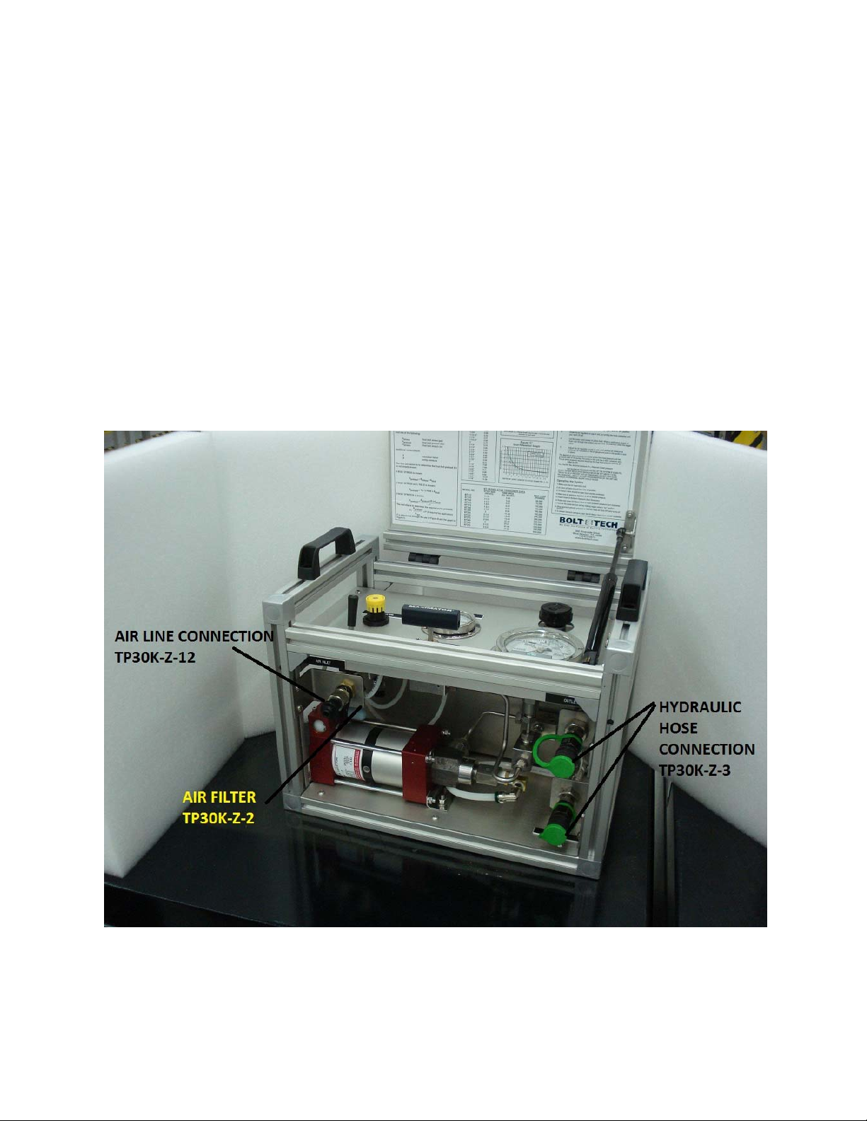
2 Air Filter TP30K-Z-2
3 Quick Connect Nipple TP30K-Z-3
4 Air Shut Off Valve TP30K-Z-4
5 Air/Hydraulic Pump TP30K-Z-'3
6 Oil Return Valve TP30K-Z-6
7 Pressure Gage TP30K-Z-7
8 Dip Stick TP30K-Z-8
9 Frame TP30K-Z-9
10 Lifting Handle TP30K-Z-10
11 Drain Plug TP30K-Z-11
12 Air Pressure Connection TP30-Z-12 (Chicago)
TP30K-Z-13 (Snap-Tite)
13) Air Pressure Gage TP30K-Z-14
MODELTP30K‐Z‐DP
PARTSDIAGRAM#1
30,000 psi Pressure Gage
TP30K-Z-7
Filler Cap / Dip Stick
TP30K-Z-8
Air Pressure Gage
TO30K-Z-14
Needle Valve
Oil Return Valve
TP30K-Z-6
Air control valve
(Pump on off valve)
TP30K-Z-4
Air Pressure Regulator
TP30K-Z-1
Model TP30K-Z'3
Parts Diagram # 2

MODELTP30K‐Z‐DP
PARTSDIAGRAM#3

TROUBLESHOOTING - PNEUMATIC SECTION
Symptom: Pump cannot be operated at low air pressure.
Cause: Excessive friction of O-rings on spool valve
Remedy: Relubricate or replace the O-rings
Symptom: Pump can only be actuated at high air pressure.
Cause: Air escapes through the piston guide in the top air cap.
Remedy: Replace O-ring on the piston extension.
Symptom: Pump runs slowly or not at all.
Cause: Exhaust or spool valve is "icy."
Remedy: Stop pump for a short while and, if necessary, clear air line and supply of
moisture.
Symptom: Pump will not run and air escapes through the exhaust muffler.
Cause: Pilot valve tappet is not sealing in top cap.
Remedy: Clean and grease tappet, check for wear and replace if necessary.
Symptom: Pump will not run and air escapes through small holes in the spool valve
housing.
Cause: Spool valve fails.
Remedy: Clean spool valve and sleeve, check O-rings and sleeve, lubricate and/or
replace.
Symptom: Pump will not run and escapes through the small holes in the bottom cap.
Cause: Pilot valve tappet is not sealing in the bottom cap.
Remedy: Clean and grease tappet, check for wear and replace if necessary.
Symptom: Pump operates at a high frequency and short strokes.
Cause: Pilot valve defective.
Remedy: Clean, check and lubricate pilot valve parts or replace if necessary.

TROUBLESHOOTING - HYDRAULIC SECTION
Symptom: Pump does not have flow, operates irregularly or does not maintain pressure.
Cause: 1. Air in the hydraulic system.
2. Suction line of excess length.
3. Suction pipe size to small.
4. Failure of one of the check valves.
5. Suction filter is blocked.
6. High pressure seal is worn excessively. .
Remedy: I.I Check suction line and pipe joints for leaks.
1.2 Check seals between air and high-pressure sections.
2. Shorten line as much as possible.
3. Increase suction pipe size.
4. Check both valve assemblies and clean or replace if necessary.
5. Clean suction filter
6. Replace seal.
Symptom: Fluid escapes through the air exhaust.
Cause. Worn high-pressure seal.
Remedy: Clean fluid from air section, relubricate and replace seal.

Safety precautions – Hydraulic Stud Tensioning
WARNING:
High-pressure hydraulics requires that the following basic rules are followed.
ALWAYS WEAR SAFETY GLASSES
when working with or near the pressurized hydraulic system.
Always check the following points before pressurizing the hydraulic system:
(a) Check that the hydraulic harness is fully connected. There should be
no loose ends and every male nipple should be connected to its
corresponding female connector.
(b) Check that each female connector is securely locked in position on
the corresponding nipple by physically pulling the connection.
(c) Check that the threaded portion of the tensioning tool is screwed on
the stud and that the thread engagement is sufficient. NOTE: The
thread projection of the stud above the top of the nut should be
sufficient to allow the tensioning tool to engage the stud a minimum
of one (1) stud diameter. Check that the tensioner is seated squarely
on the bridge piece, and that the bridge is seated squarely on the work
piece.
Never exceed the maximum working pressure for each stud size or tensioner.
Maximum working pressure for standard tensioners is 21,750 psi.
Never exceed the maximum extension for the equipment.
NOTE: A line will appear when the tool is close to maximum extension.
When pressurizing the system,
observe the gauge, and be ready to stop, at the required pressure.
Never leave the pressurized system unattended. If you must leave the area release
the pressure and ensure that the return to tank valve on the pump unit is fully open.
Read both Tooling and Hydraulic Hand Pump and Control Console Operation and
Maintenance Manuals prior to operation.
Never pressurize the Control Console or Hand pump unless the outlet is either
connected to the tensioning system or is safely blanked with a blanking plug.
Table of contents
Popular Water Pump manuals by other brands

Gardena
Gardena FSP 3500 operating instructions

Hi-Force
Hi-Force AHP1120 Series instruction manual

BUSCH
BUSCH Mink MM 1324 AV Installation and operating instructions

Goulds
Goulds MODEL VIT Installation, operation and maintenance instructions

Binks
Binks MX412UCA Service manual

SKF
SKF Lincoln P205 Assembly instructions


