Bomet Gemma S290 User manual

OWNER'S MANUAL
WARRANTY CARD
SPARE PARTS CATALOGUE
AUTOMATIC CONVEYOR
VEGETABLE PLANTERS
Gemma
S290 - 3-ROW PLANTER
S290/1 - 4-ROW PLANTER
S290/2 - 5-ROW PLANTER
PRIOR TO STARTING WORK, PLEASE READ THIS
OPERATING INSTRUCTIONS
BOMET®
Spółka z ograniczoną odpowiedzialnością
Spółka Komandytowa
07-100 Węgrów, ul. B. Joselewicza 2
tel. (+48 25) 691 78 06
Printed in Węgrów by Bomet®.
Węgrów 2019, Edition 1, Eng
Original manual

Copying of the manual or its parts is allowed only with the written permission of Bomet®

- 1 -
BOMET®
Spółka z ograniczoną odpowiedzialnością
Spółka Komandytowa
07-100 Węgrów, ul. B. Joselewicza 2
tel. (+48 25) 691 78 06
DECLARATION OF CONFORMITY
for a machine
According to the Ordinance of Minister of Economy of 21 October 2008 (Journal of Laws "Dziennik Ustaw" No.
199, item 1228)
and European Union Directive 2006/42/EC of 17 May 2006 (Journal of Laws UE L157 p.24-86)
we declare with full responsibility that the machine:
Machine:
VEGETABLE PLANTER
Type/model:
S290
Serial number:
............
Year of production:
201 …..
Function:
Planting of tuberous vegetables
to which this declaration relates, is in conformity with:
The Ordinance of Minister of Economy of 21 October 2008 on essential
requirements for machines (Journal of Laws "Dziennik Ustaw" No. 199, item 1228)
and European Union Directive 2006/42/EC of 17 May 2006
Person responsible for technical documentation of the machine: Andrzej Sińczuk, ul. B. Joselewicza 2, 07-100 Węgrów
Following harmonized standards have been applied:
PN-EN ISO 12100:2012
PN-EN ISO 4254-1:2016P
This EC Declaration of Conformity loses its validity if the product is misused or modified
without proper authorization.
THE MANUAL CONSTITUTES MACHINE BASIC EQUIPMENT!
Węgrów, .......................................
..........................................................
Place and date of issue
Name and function of the signatory

- 2 -
W A R R A N T Y C A R D
Automatic vegetable planter type S290
Serial number ................................................
Date of production..... 201 …..
Inspector signature ...............................................
Date of sale ..................................................
Seller signature .......................................
.............................................
...................................................
Seller stamp
Manufacturer stamp
CAUTION: It is seller’s obligation to fill in the warranty card and complaint forms carefully
(legibly). Lack of e.g. date of sale or stamp of sales point will put the user at risk of not
acknowledging possible complaints. Warranty card with any written corrections or filled in
illegibly –is invalid.
Warranty proceedings rules
1. A user is understood as a natural or legal person purchasing an agricultural equipment and
a seller –as a corporate unit providing equipment to the user and a manufacturer - as a
manufacturer of agricultural equipment.
2. Manufacturer ensures good quality and efficient operation of the planter, to which the
warranty card is attached.
3. Any defects or damage of the planter shall be fixed free of charge at the place of the
purchaser in the period of 12 months from the sales date.
4. Any revealed defects or damages shall be reported on a complaint form in person, by post
mail or by phone.
5. If during warranty period, a necessity of performing 3 warranty repairs occurs, and the
product will still reveal defects disabling its usage according to its intended use, the
purchaser is entitled to have the product exchanged into a new, flawless one or refund.
6. If the manufacturer, a seller and a user will not establish another deadline for considering
the complaint, exchanging the product or refund should be made within 14 days from the
date of reporting it by the user.
7. Warranty repairs do not cover repairs caused by:
- using the planter inconsistently with the manual and intended use,
- acts of God or others for which the manufacturer does not take responsibility.
These repairs can be made only at the expense of the user, purchaser.
8. The manufacturer can cancel warranty on the product in case of stating:
- introducing structural changes,
- occurring any damages caused by acts of God,
- lack of necessary records or any records made by one’s own in the warranty card,
- using the planter inconsistently with intended use or manual.

- 3 -
Complaint form No. 1
Automatic vegetable planter S290
Serial number ....................................... Date of sale ................................
.....................................................
seller’s signature and stamp
Complaint protocol number ...........................
Complaint form No. 2
Automatic vegetable planter S290
Serial number ....................................... Date of sale ................................
.....................................................
seller’s signature and stamp
Complaint protocol number ...........................
Complaint form No. 3
Automatic vegetable planter S290
Serial number ....................................... Date of sale ................................
.....................................................
seller’s signature and stamp
Complaint protocol number ...........................

- 4 -
After repair I received technically efficient machine
on .............................................
……………………………………………………..
user’s signature
Notes:
.......................................................................................................................
.......................................................................................................................
.......................................................................................................................
- 5 -
IDENTIFICATION
AUTOMATIC VEGETABLE PLANTER
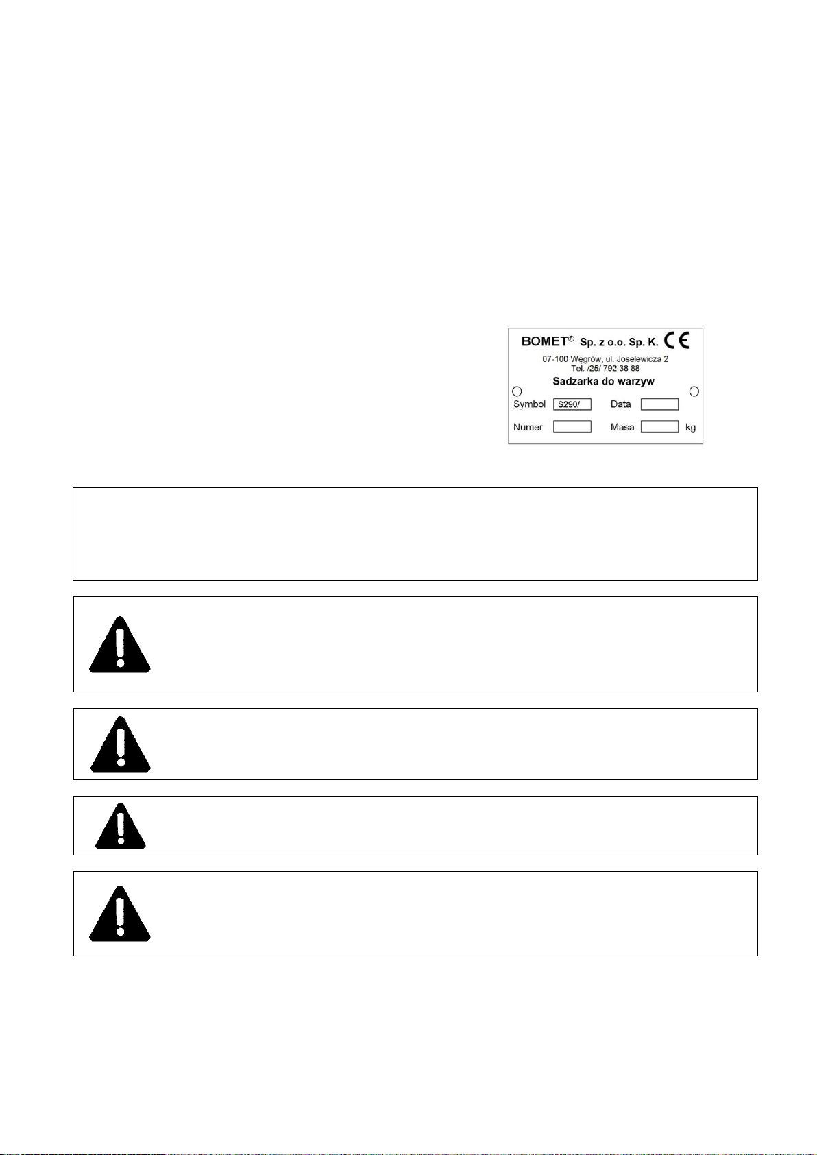
The S290 automatic conveyor vegetable planter is a 3-row, 4-row or 5-row machine
with a rating plate, fitted in the front part of the planter frame. Basic data which serves for
identification of the machine: manufacturer’s name, machine symbol, serial number, year of
production, is put there.
Data placed on the rating plate serves for identification of the planter and ought to
correspond to the following data, filled in during the sales.
Symbol U290 .....
Year of production 201 ....
Serial number ......................................
IT IS ADVISED THAT THE SUPPLIER OF MACHINES, BOTH NEW AND USED ONES,
KEEP THE SIGNED BY THE PURCHASER CONFIRMATION OF RECEIPT OF THE
MANUAL ALONG WITH THE MACHINE.
THE MANUAL CONSTITUTES MACHINE BASIC EQUIPMENT
KEEP THIS INSTRUCTION FOR FUTURE REFERENCE
CAUTION!
When lending the machine to another person, the manual shall be attached to
the machine.
CAUTION! REMEMBER!
During transport, it is absolutely forbidden to stay on the planter.
CAUTION!
During operation, it is necessary to pay particular attention to backlash of
screw connections. Therefore, it is necessary to check and tighten screw
connections after stopping the tractor and turning off the engine.

- 6 -
TABLE OF CONTENTS
W A R R A N T Y C A R D.................................................................................................................2
1. INTRODUCTION.............................................................................................................................7
2. INTENDED USE OF THE PLANTER...............................................................................................7
3. SAFETY PRECAUTIONS AND WARNINGS...................................................................................8
3.1. Symbols: meaning and application...........................................................................................8
3.2. Expected use...........................................................................................................................8
3.3. Description of residual risk.......................................................................................................8
3.4. Assessment of residual risk......................................................................................................9
3.5. Regulations for occupational health and safety........................................................................9
3.6. Standard conformity...............................................................................................................11
3.7. Manufacturer's responsibility and guarantee..........................................................................12
3.8. Noise and vibrations...............................................................................................................12
3.9 Safety signs and captions.......................................................................................................12
4. USAGE REGULATIONS ...............................................................................................................13
4.1. General information................................................................................................................13
4.2. Construction and operation of the machine............................................................................14
4.3. Equipment and fittings............................................................................................................15
4.4. Preparing the tractor for operation..........................................................................................15
4.5. Preparing the planter for operation.........................................................................................16
4.6. Mounting the planter on the tractor.........................................................................................16
4.7. Adjustment and setting of the planter.....................................................................................17
4.8. Operation with the planter......................................................................................................19
5. TECHNICAL OPERATION............................................................................................................20
5.1. Instructions on maintenance of the planter.............................................................................20
5.2. After-seasonal maintenance of the planter.............................................................................20
5.3. Storage of the planter.............................................................................................................20
5.4. Replacement of the working elements ...................................................................................21
5.5. Lubrication instruction............................................................................................................21
5.6. Detection and removal of inefficiencies..................................................................................22
6. TRANSPORTATION ON PUBLIC ROADS....................................................................................22
6.1. Planter transportation by means of transport..........................................................................22
6.2. Transportation of the planter on the tractor ............................................................................22
7. DISASSEMBLY.............................................................................................................................23
8. TOTALING ....................................................................................................................................23
9. TECHNICAL CHARATERISTICS..................................................................................................24
SPARE PARTS CATALOGUE ..........................................................................................................25

- 7 -
1. INTRODUCTION
Dear customer,
Congratulations on the choice of the product of Bomet®company.
The aim of this manual attached to each machine is to make a user acquainted with a
construction, operation and adjustment of the automatic conveyor planters. Its aim is also
warning about existing or possible threats. The manual also contains information on
preparation of the planter for operation and for transportation on public roads.
Strict compliance with recommendations included in the content of the manual will
ensure a long-term and non-failure operation and contribute to reduction of operating costs of
the machine.
Each section of the manual (according to the contents) presents proper issues in
detail. If there is any unclear information for the user, they can obtain exhaustive explanation
by writing to the manufacturer’s address (the address is on the cover) – you are asked to
give: exact address of the purchaser of the machine, machine symbol, serial number, year of
production, year and issue number of the manual.
Terms used in the manual: left side, right side, back and front –refer to the settings of
an observer with his face turned according to the direction of the machine drive.
Warranty proceedings regulations and rights resulting from them, are given in the
warranty card, attached to each planter.
2. INTENDED USE OF THE PLANTER
Automatic conveyor 3-row, 4-row and 5-row planters are intended to operate
exclusively in the agriculture. Using them for other purposes shall be understood as using
them against the intended use. Meeting requirements referring to operation of the machine,
its maintenance and repairs according to recommendations of the manufacturer and strictly
complying with them state the condition of using it according to the intended use.
The machine shall be employed and operated only by people acquainted with its
detailed characteristics and procedures in the field of safety. Regulations concerning accident
prevention and all the basic regulations in the field of occupational health and safety and also
traffic regulations should be always abided by.
Automatic vegetable planters of S290 series are multi-row planters mounted on the
tractor three-point suspension system. Planters should be aggregated only with 2N and 2
tractors classes with suspension category II, equipped with standard ballasts of the front axle
to keep the required controllability factor (s ≥ 0.2).
The machines are designed for planting vegetables such as garlic, broad beans or
spring onions in well-cultivated soil on plain terrain and on slopes up to 8.5. An automatic
planter can be used for planting garlic, broad beans and spring onions, after mounting
appropriate cups on the transport chain and setting the appropriate spacing of the planted
seeds.
In one work cycle the planter performs all the work associated with planting cloves or
vegetable seeds, i.e. plows furrows, automatically plants cloves and covers them with soil.
The planter allows to plant seeds in a minimum inter-row spacing of 12cm. The maximum
spacing possible to be obtained for a 3-row planter is 48cm, for a 4-row planter 32cm, and for
a 5-row planter, 24cm. By replacing the gear wheel in the chain transmission and changing
the ratio, it is possible to adjust the spacing by planting seeds in a row in the range of 9.5 cm
to 21.5 cm.
- 8 -
3. SAFETY PRECAUTIONS AND WARNINGS
3.1. Symbols: meaning and application
In the present manual symbols are used in order to draw the reader’s attention and
stress certain particularly important aspects requiring discussion.
DANGER
This indicates danger, with a possible serious accident risk. Not obeying recommendations
marked with this sign may cause a situation of a serious risk of sustaining an injury by the
operator and/or people nearby! Obey strictly these recommendations!
CAUTION
The symbol indicates possibility of damaging the machine or other object and demands to
be cautious. It is important advice which should be paid special attention!
REMEMBER
The symbol indicates advice or notice regarding key functions or useful information
concerning proper functioning of the machine.
3.2. Expected use
Automatic vegetable planter of S290 series has been designed, built and adjusted for
planting garlic, broad beans or spring onions in two, three or five rows on flat and wavy fields,
on all types of soil kept in good culture, stoneless, of humidity enabling proper operation.
Planter should be aggregated with tractors class 2N and 2 or higher, equipped with
suspension system category II and front axle standard ballasts to keep the required
controllability factor. Operation with a planter can be performed on slopes up to 8.5.
REMEMBER
Regulations concerning the intended use and configurations, provided for this machine are
the only ones, which are exclusively allowed. The machine shall not be employed for other
purposes than those, which have been provided for it. The regulations given in this manual do
not substitute obligation towards present regulations with force of a statute, referring to
standards concerning safety and prevention from misadventure, but they summarize them.
3.3. Description of residual risk
Residual risk results from wrong or incorrect behavior of the planter operator. The
greatest danger can occur in performing following activities:
-operation of the planter by minors and also people not acquainted with the manual or
not having qualifications for driving an agricultural tractor,
-operation of the planter by people with a disease, in a state indicating for using alcohol
or narcotic drugs,
-transportation and operation without proper safety measures,
-aggregation of the planter with a tractor if the operator is between the machine and the
tractor with the engine working,
-operation when people or animals stay within the range of operation of the assembly
tractor + machine,
-maintenance and adjustment near the planter when the tractor engine is working and
the machine is not protected against falling down.
When describing residual risk of the vegetable planter, the planter is treated as a machine,
which since the moment of starting the production, has been designed and manufactured
according to the present technique condition.
- 9 -
3.4. Assessment of residual risk
During operation of the vegetable planter, threat and residual risk can be limited to the
minimum when such recommendations are abided by:
-careful reading the manual,
-prohibition of people staying on the planter during transportation,
-prohibition of people staying between the tractor and the planter when the tractor
engine is working,
-all adjustment, maintenance and lubrication of the planter shall be performed only with
the tractor engine stopped,
-repairs of the planter performed only by people trained in this field,
-operation of the machine by people who have qualifications to drive agricultural
tractors and are familiar with the manual of the machine,
-protection of the planter against children access.
Although BOMET®company takes responsibility for pattern-designing and construction
in order to eliminate danger, certain risk elements during automatic planter operation are
unavoidable.
1) Danger of being caught or hurt by the frame edges or marker sharp endings and
adjustment elements of the planter press wheels during aggregation or changing
transportation-operation position and inversely.
2) Danger of wound or abrasion by sharp working elements of the machine when
performing maintenance or adjustment resulting from improper position of the operator during
these activities.
3) Danger of being crushed by the moving elements of the transport chain with cups or
the drive chain transmission as a result of the operator's improper position during
maintenance and adjustment.
4) Danger of turning over the machine during storage or transportation. When stored to
keep stability, the planter should be set on the flat ground leaning on road wheels and
markers. The planter shall be aggregated only with tractor classes recommended by the
manufacturer.
3.5 Regulations for occupational health and safety
CAUTION
In order to avoid threats, before starting operation with the planter, please read
the present manual and follow these rules concerning threats and safety
measures:
General regulations
Apart from this manual, one shall also follow traffic regulations as well as occupational
health and safety regulations.
Warnings (pictograms) placed on the planter give advice concerning safety of the user and
other people, and avoiding accidents.
When driving on public roads, it is obligatory to follow regulations included in Highway
Code.
Before each using the machine, it is necessary to check if all elements of the planter are in
a good condition. Damage incurred shall be fixed without delay and possible deficiencies
filled up.
It is recommended to cooperate with a tractor equipped with a cabin or a protective frame.
Avoid staying within the range of the working planter, outside the designated platform.
Before leaving the tractor cabin and before each activity made at the planter, stop the
tractor engine and remove the key from the ignition switch.
- 10 -
The planter shall be stored in a dry room, on the tough and flat ground. When lowering the
planter onto the ground, keep particular caution. Danger of injury!!!
Aggregation
Keep particular caution when connecting the planter with a tractor and during
disconnection.
It is forbidden to stay between the planter and a tractor during any activities performed with
a hydraulic system lever.
While aggregating the planter with a tractor, it is forbidden to stay between the tool and the
tractor at the tractor engine working.
When performing any maintenance at the planter, it is necessary to stop the engine,
remove the key from the ignition switch and pull the handbrake.
Pivots of the planter suspension system shall be secured only with the use of typical
protection in the form of cotter pins.
The planter shall be aggregated only with recommended tractor classes equipped with
front axle ballasts.
The planter can be operated by a person with qualifications allowing for using agricultural
tractors.
During aggregation, keep the minimum load of the tractor front.
CAUTION
Operation with a tractor of another class than recommended by the manufacturer may cause
threat of stability loss in operation or in stoppage. Front axle load cannot be less than 20% of
the tractor’s weight.
Operation
The planter can be operated by a person with qualifications allowing for using agricultural
tractors and acquainted with the planter manual.
It is not allowed for other people not acquainted with the manual to operate the planter.
It is not allowed for children and people after drinking alcohol to operate the planter.
The planter shall be raised onto the tractor suspension system easily, without jerks or
vibrations.
Raise the planter upwards each time when turning and making returns.
Work with a planter on slopes with gradient exceeding 8.5is not allowed.
At each getting off the tractor by the operator, leave the planter in the lowered position.
Removal of clogging on the markers can be performed after stopping the tractor with the
machine lowered onto the ground and the tractor engine stopped.
It is not allowed to use tractor reverse gear during work, when the machine is in the
working position.
All maintenance (lubrication, repairs, cleaning etc.) shall be performed with the planter
lowered onto the ground, the tractor engine stopped, key taken out from the ignition switch
and handbrake pulled.
Take special care when checking the planting, especially filling the cups in the tank. Use
protective gloves or other personal protective equipment.
People operating agricultural equipment should be equipped with working clothes and
footwear, and personal protection measures appropriate for existing threats, eg. gloves,
glasses.
!!! CAUTION!!!
Absolute prohibition of working with open or removed shields.
It is forbidden to remove the shields when the planter is in operation.
- 11 -
Transportation
Transportation of a planter by means of transport from the manufacturer to a sales person
or a client is described in the section ‘Transportation on public roads’ in detail. One shall
remember safety rules during the loading and proper fixing of the planter on a car trailer.
Hooks for ropes or chains are marked with pictograms.
The planter transported on public roads must be equipped with portable light and warning
devices and a triangular sign for low-speed vehicles, fixed in special handles on the
planter frame, see details in section ‘Transportation on public roads’.
It is forbidden to transport any people or items on the frame (grain sacks), or to
conduct transport journeys with a full tank.
With regard to overlapping of the machine due to considerable width of the planter and a
fixed connection with the tractor, keep caution especially at returns during operation and
turnings during transportation on public roads.
Keep extreme caution while making a turn of a tractor with a mounted planter, both during
transportation and also while making returns in the field, especially when there are any
people or items nearby.
Driving speed of the tractor with the planter during transportation cannot exceed:
- when driving on hardened roads with flat surface –15 km/h,
- when driving on field ways –10 km/h.
Storage
Disconnecting the planter from the tractor can take place only after the tractor engine is
stopped, key removed and the handbrake pulled.
The planter shall be stored in a dry room, on the tough and flat ground. When lowering the
planter onto the ground, keep particular caution - danger of being injured or crushed!!!
During storage, the planter should be set firmly on working elements, i.e. markers and
road wheels.
The planter should be stored in places where there is no possibility of accidental injury of
people or animals, on the flat ground, preferably under a roof.
The automatic conveyor planter shall be stored in a clean condition.
Threat!
Pay attention to sharp frame endings, markers, leveling roller - danger of being hurt, keep
caution during operations near the planter.
Others
It is not allowed to use the planter for other purposes than given in the manual.
CAUTION
Not following these rules may cause threat to the operator and other people and also may
cause damage to the planter. Any damage resulting from not following these rules is the only
responsibility of the user.
3.6. Standard conformity
The machine has been designed and made in accordance with standards concerning
safety in the machine industry, valid on the day of marketing the planter. Particularly, the
following legal acts and standards have been taken into account:
2006/42/EC - Directive on machinery safety introduced by the Ordinance of Minister of
Economy on 21 October 2008 (Journal of Laws ‘Dziennik Ustaw’ No. 199, item 1228).
PN-EN ISO 12100:2012P - Machinery. Safety. General principles for design. Risk
assessment and risk reduction.
PN-EN ISO 4254-1:2016P –Agricultural machinery. Safety. Part 1: General
requirements.

- 12 -
PN-ISO 730-1:2018E –Wheeled agricultural tractors. Rear three-point suspension
system. Categories N1, 1, N2, 2, N3, 3, N4 and 4. (orig.)
PN-ISO 2332:1998P –Tractors and agricultural machinery. Mounting machinery on a
three-point suspension system. Free space zone.
PN-ISO 3600:1998P –Tractors, agricultural and forest machinery, mototools. Manual.
Contents and form.
PN-ISO 11684:1998P –Tractors, agricultural and forest machinery, mototools. Safety
signs and hazard pictograms. General provisions.
3.7. Manufacturer’s responsibility and guarantee
In relation to the machine described in this manual, Bomet®company does not
acknowledge any civil responsibility towards:
-using the machine improperly or inconsistently with the manufacturer’s recommendations,
-using the machine in a way breaking domestic law concerning safety and preventing from
unfortunate accidents,
-non-compliance or improper following regulations cited in this manual,
-making unauthorized changes in the machine,
-using the machine by unqualified staff,
-using spare parts that are not original.
As long as the purchaser wants to make use of warranty, he should strictly follow
recommendations and regulations given in the manual. In particular:
-he should work only in the given ranges of the machine operation,
-he should always perform unchangeable and thorough maintenance,
-only operators with proper abilities and qualifications shall be allowed to use the machine,
-he should use only original spare parts recommended by the manufacturer.
3.8. Noise and vibrations
During the operation of the S290 automatic conveyor planter for the operator there is
no threat caused by noise contributing to the loss of hearing because the planter is an
inactive machine and the workplace of the operator is in the tractor cabin.
There is no threat caused by vibrations when working with a planter because the
operator’s workplace is located in the tractor cabin where the seat is amortized and properly
ergonomically shaped.
3.9 Safety signs and captions
Automatic conveyor planter of S290 series is equipped with all devices that ensure
safe operation. Where it is not possible to secure dangerous places entirely due to the proper
operation of the planter, there are warning signs –pictograms which indicate for possibility of
danger and present manners of avoiding it.
In table 1 pictograms placed on the machine and their meaning have been specified.
Safety pictograms should be protected against being lost and against loss of legibility. Lost or
illegible signs and captions should be exchanged with new ones. It is required that new
assemblies employed during repair were marked with all safety signs predicted by the
manufacturer. If you want to buy pictograms, write to the manufacturer’s address or send
information to the e-mail address and give the sign number (according to the table 1), version
and year of issuing this manual.
,

- 13 -
Table 1. Safety signs and captions
No.
Pictogram
Meaning
Location
1
2
3
4
1.
(Rating
plate)
Rating plate
At the front of the frame
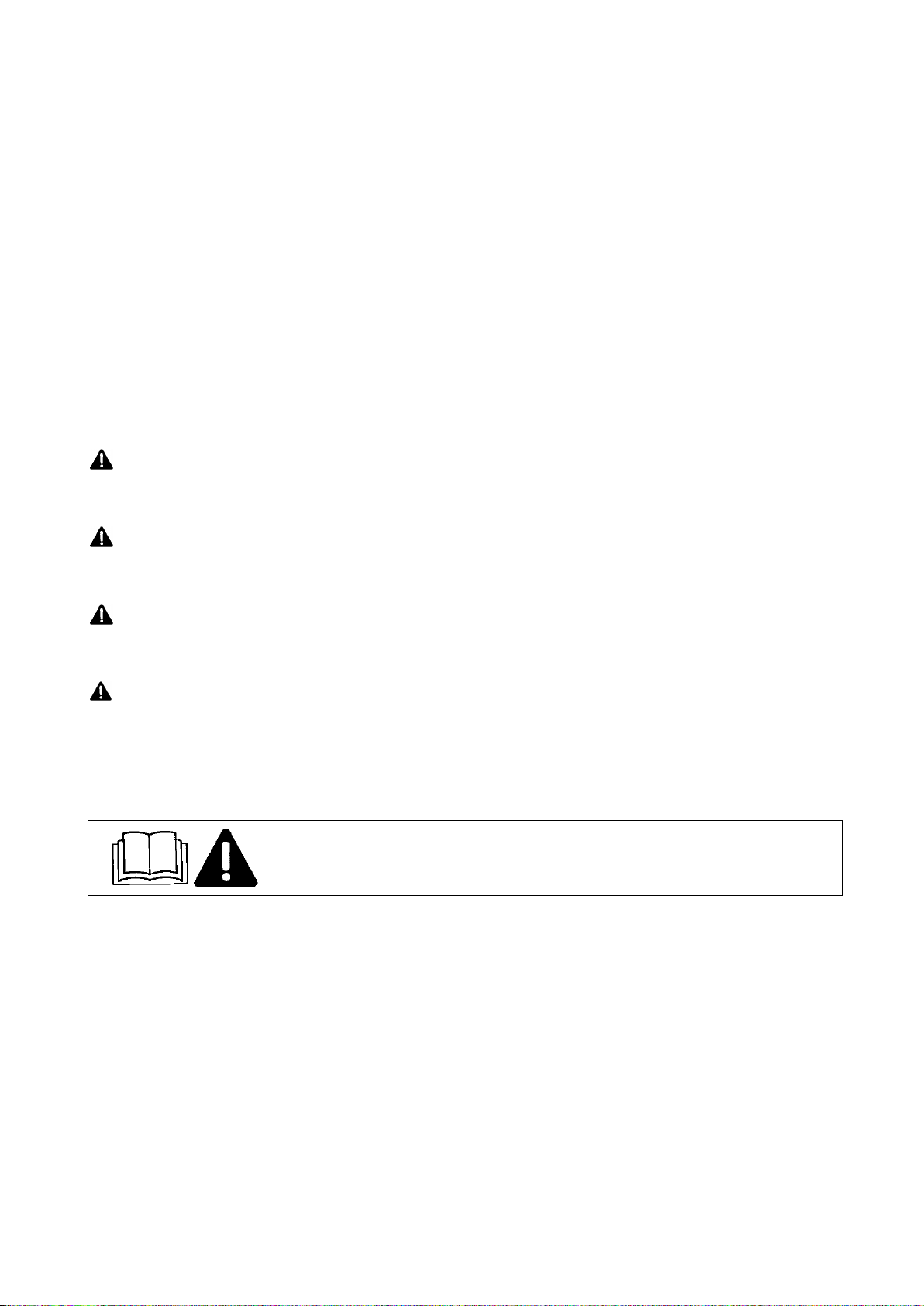
2.
Before operating the machine, read the
manual.
At the front of the three-
point suspension system
3.
Caution. Before operation turn off the
engine and remove the key from the
ignition switch.
At the front of the three-
point suspension system
4.
Do not stay near the lift rods, while
controlling the lift.
At the front of the three-
point suspension system
5.
Caution. Risk of being caught by the
chain transmission. Do not put hands into
the planter tank during operation.
On the planter shield
6.
Caution. Do not reach crushing area if
the elements can be in motion
On the planter frame
7.
Danger of hurting a leg. Keep the safe
distance from the working roller
On the planter frame
8.
Prohibition of work without shields
On shields
9.
Marking places of loading hooks
On the planter frame
10.
Marking lubrication points
On the planter frame
11.
Symbol of permissible transport speed
At the back of the planter
tank
12.
Company logo
On the planter tank
4. USAGE REGULATIONS
4.1. General information
The S290 automatic conveyor planter is a machine suspended on the tractor three-
point suspension system. The planter is available as a 3-row, 4-row or 5-row machine. The
planter is suitable for operation on slopes not exceeding 8.5and cooperate with tractor
classes 2N and 2 (see table 4) equipped with suspension system cat. 2 and standard wheel
ballasts.
- 14 -
4.2. Construction and operation of the machine
The S290 automatic conveyor planter (Figure 1) is a machine mounted on the tractor
three-point suspension system. Planters have a modular construction, they have the same
elements, they only differ in the number of rows. The planter is available as a 3-row, 4-row or
5-row machine. The construction of the 4-row planter is described below.
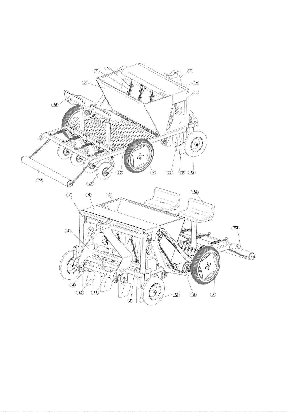
Figure 1. Automatic conveyor 4-row planter: 1 - frame, 2 - tank, 3 - tractor three-point suspension system,
4 - hitching beam, 5 - transport chain conveyor, 6 - chain keeper, 7 - road wheels, 8 - drive
sprockets, 9 - drive chain transmission, 10 - markers, 11 - chute pipe, 12 - support wheels,
13 - press wheels, 14 - leveling roller, 15 - seats, 16 - platform
The basic component of the planter is a welded frame (1) on which a metal tank (2) is
installed. At the front of the frame there is a three-point suspension system (3) with a hitching
beam (4). In the tank there are transport chain conveyors with cups (5), leaning against the
guides (6). The transport chain receives the drive from the road wheels (7) of the planter
through the drive chain transmissions (8). The upper roller of the transport conveyor and the
charging funnel are covered from the top by a cover (9). At the front of the planter frame
there are markers (10) attached that plough the furrows. In the markers there are chute pipes
- 15 -
(11) which supply furrows with seeds. The planting depth is adjusted in strokes with front
support wheels (12). At the back of the planter there are press wheels (13) and a leveling
roller (14). The roller covers the seeds and levels the ridges. The planter is equipped with
seats (15) and a platform (16) facilitating the control of filling the cups with seeds. The
platform and seats can only be used while working.
!!! CAUTION!!!
It is absolutely forbidden to use the platform and seats during transportation.
The platform and seats can only be used while working.
The automatic conveyor planter is a machine intended for planting garlic, broad beans
or spring onions, after proper adjustment of the size of the transport chain cups, and
adjustment of the planting spacing in the row and adjustment of the inter-row spacing. The
operation of the conveyor planter is based on collecting of individual garlic cloves or broad
bean seeds and onions by the transport chain cups directly from the tank, and transporting
them to the charging funnel. Seeds drop freely through charging funnels and chute pipes into
the markers and into the furrow made by this marker. The leveling roller behind the planter
covers the planted seeds with soil and levels the ridges.
4.3. Equipment and fittings
The manufacturer delivers the planter for sale assembled. The manual with a spare
parts catalog and a warranty card as well as two gear wheels with Taper Lock sleeves to
adjust the planting spacing to the crop, are delivered along with the machine by the
manufacturer. Basic equipment of the machine does not involve portable light and warning
devices and a triangular sign for low-speed vehicles which are available at agricultural
equipment storehouses.
REMEMBER
Manual with a spare parts catalogue comprise basic equipment of the planter.
Each user of the planter shall have light and warning signs, in working order, and a
triangular sign for low-speed vehicles (sign description is available in the section
‘Transportation’). Not having them during transportation may result in an accident. For
damage incurred during an accident the user of the machine is responsible.
4.4. Preparing the tractor for operation
Preparation of a tractor to cooperation with a planter consists in checking its general
efficiency in accordance with the tractor manual (pay particular attention to the proper
operation of the suspension system). In addition, it is necessary to uninstall from the tractor
elements disabling mounting the machine or disabling its operation. It is mandatory to
aggregate the planter with recommended tractor classes equipped with standard ballasts of
front axle and rear wheels in accordance with data given in the technical characteristics of
the tractor. Air pressure, particularly in rear tires of the tractor should be equal in both wheels
and in accordance with the tractor’s manual!
Before suspension of the machine, lower rods of the tractor’s suspension system shall
be set in lower position at the same height (distance between joints and the ground is
minimum 200 mm). Rods set at the equal height from the ground facilitate mounting the
planter on the tractor.

- 16 -
4.5. Preparing the planter for operation
Preparation of a new planter to operation and after storage period (e.g. after winter)
consists in checking its technical condition and most of all durability of connections of working
elements with the frame. In case of stating damage or worn elements it is necessary to
exchange them into new or regenerated ones. Otherwise, it can lead to reduction of the
machine work quality.
CAUTION
It is forbidden for the operator to stay between the tractor and the machine at the tractor engine
running. The planter shall be raised easily, without jerks or vibrations.
In addition, it is necessary to:
- check screw connections, in case of backlash tighten the nuts,
- determine and set the correct inter-row spacing for a given crop,
- determine and set the correct marker operation depth, by adjusting the front wheels,
- determine and install the correct cups in the transport chain for a given crop,
- check and if need be perform adjustment of the chain transmissions tension,
- lubricate the planter in accordance with recommendations (see section "Lubrication
instruction").
- check the pressure in the planter tires.
CAUTION
The planter tank should be filled at a stoppage directly before sowing in the field, after lowering
the planter onto the ground and turning off the tractor engine and the key removed from the
ignition switch.
CAUTION
Loading of seeds into the tank should be made from the ground (sacks up to 25kg), the
height of the tank's edge allows for safe loading from the ground.
CAUTION
All maintenance in the planter shall be performed before installing it on the tractor.
4.6. Mounting the planter on the tractor
When mounting the planter on the tractor, perform following activities, while
disconnecting should be performed in reverse order:
- disassemble a tool latch bar from lower rods of the tractor three-point suspension system,
- disassemble the hitching beam of the planter and install it in the place of the hitching beam
(lower rods of the three-point suspension system) on the tractor, securing it with typical
cotter pins,
- drive to the machine with the tractor so that the hitching beam is mounted in the yoke
brackets of the planter suspension system,
- turn off the tractor engine, remove the key from the ignition switch and pull
handbrake,
- install locking pivots, securing them with typical cotter pins,
- using a pivot, link the upper connector of the tractor with the planter frame rack and secure
with a typical cotter pin,
- tighten gently chains of lower rods of the tractor, keeping the symmetry between the planter
suspension and the tractor,
- install portable light and warning signs and a triangular sign for low-speed vehicles.
CAUTION
It is forbidden to connect the machine to a tractor when the tractor engine is running. It is
forbidden to use other elements to secure the tool suspension system than recommended by the
manufacturer.
CAUTION
Pay particular attention when aggregating the planter, do not keep place between the planter
and the tractor.

- 17 -
Disconnecting the planter from the tractor is performed in reverse order, it is necessary
to leave the machine on the flat and even ground and secure it against moving.
4.7. Adjustment and setting of the planter
The correct and good quality of the planter's work depends on the proper leveling of
the planter and then depending on the crop, the appropriate setting of the planting depth,
setting of the inter-row width and the planting spacing in a row.
Transversal leveling ensures determining equal operation depth of right and left sections of
the planter and is performed with the right hanger of the tractor suspension system. After
performing adjustment the tank of the planter, visible from the back, after gaining full
operation depth should be set horizontally.
Longitudinal leveling ensures determining the equal operation depth of the working
elements at the front and rear of the planter. Longitudinal leveling is performed by shortening
or lengthening the upper connector of the tractor suspension system. Properly leveled planter
should have the frame and the tank set in parallel to the field surface.
Adjustment of the planting depth is performed with
the front support wheels. The change of the seed
planting depth is performed by changing the position
of the support wheel arms (2) and determining its
position in the appropriate guide hole (1). The planter
construction allows for a step change in the planting
depth in the following ranges of 3cm, 5cm, 7cm and
9cm. Such planting depths concern recommended
agrotechnical planting depths for garlic, broad beans
and spring onions.
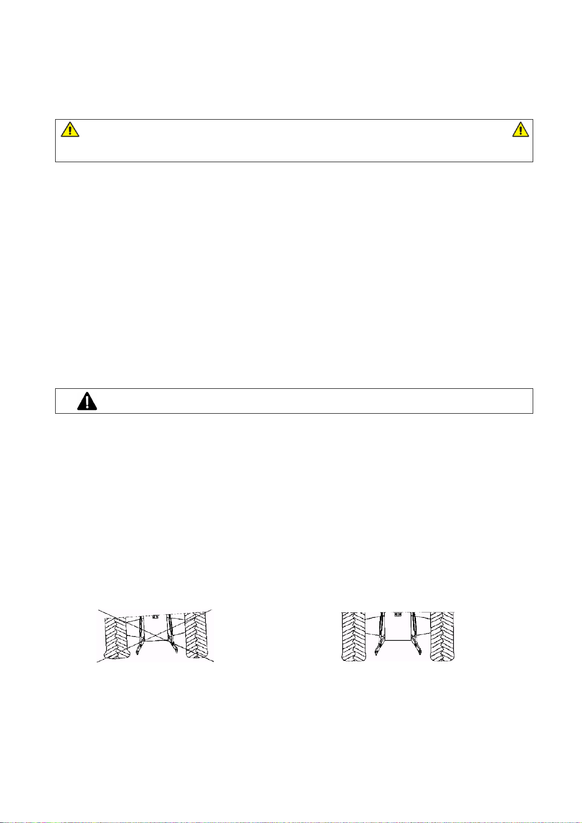
Adjustment of inter-rows, minimum inter-row
spacing in the planter is 12cm, and the maximum
spacing varies depending on the number of rows
planted. For a 3-row planter, the maximum inter-row
spacing is 48cm, for a 4-row it is 32cm and for a 5-
row it is 24cm.
In order to change the marker spacing (1), loosen the
bolts fixing the U-bolts (2) on the planter frame (3),
then set the markers to the appropriate spacing and
tighten the fixing bolts.
Replacement of cups. There are two planting cup
dimensions of Ø28mm and Ø36mm to adjust to the
planted crops and their seeds size.
In order to change a cup (1) in the transport chain,
unscrew the M5x25 (2) bolt that tightens the cup in
the connecting link (3), remove the cup and install
another one.
- 18 -
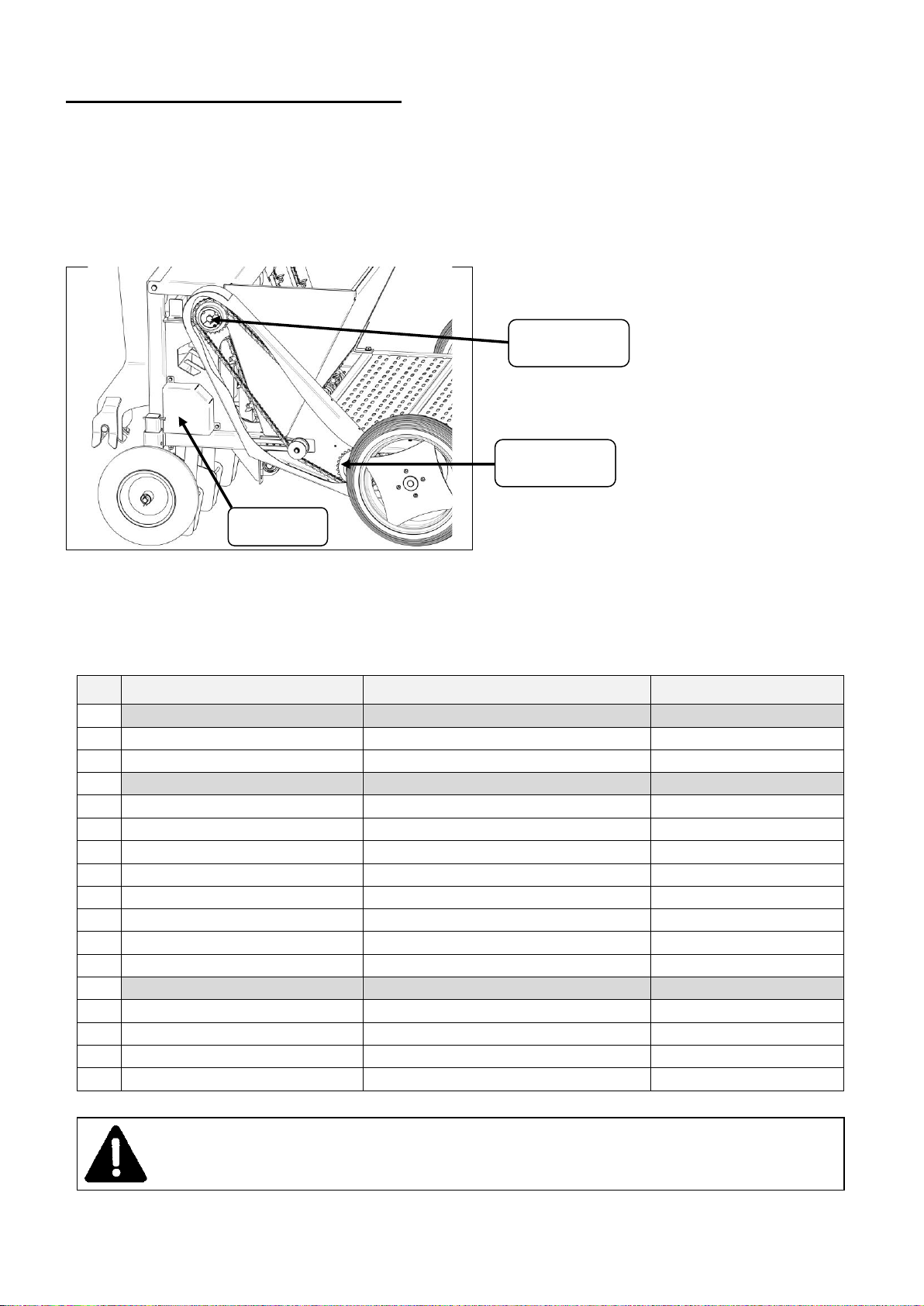
Changes in planting spacing in a row are made by changing the upper drive wheel in the
drive gear. Depending on the crop, the seed sowing should be set properly in the row. By
changing the gear wheel, the rotational speed of the drive shaft of the transport chain
conveyor is changed. The replaceable wheel is mounted on the upper roller with a Taper
Lock sleeve. The standard equipment of the planter includes gear wheels z = 13 with Taper
Lock 1008, z = 16 with Taper Lock 1610 and z = 25 with Taper Lock 2012.
As a standard the planter is prepared for planting with 18cm spacing with the transport chain
with 16 cups and a replaceable wheel z = 25.
Before starting work, if there is a need to change the planting spacing, select the
appropriate replaceable gear wheel together with the Taper Lock sleeve and replace the
upper gear wheel. The table below presents the achievable seed planting spacing with
appropriate replaceable gear wheels together with the specified types of Taper Lock sleeves.
Table 2. Planting spacing for the transport chain with 16 cups
No.
Number of tines of the replaceable
wheel
Taper Lock sleeve
Planting spacing
1.
z = 13*
1008
9.5 cm
2.
z = 14
1108
10.0 cm
3.
z = 15
1210
10.5 cm
4.
z = 16*
1610
11.5 cm
5.
z = 17z
1610
12.0 cm
6.
z = 18
1610
13.0 cm
7.
z = 19
1610
13.5 cm
8.
z = 20
1610
14.0 cm
9.
z = 21
1610
15.0 cm
10.
z = 22
1610
16.0 cm
11.
z = 23
1610
16.5 cm
12.
z = 24
2012
17.0 cm
13.
z = 25*
2012
18.0 cm
14.
z = 26
2012
18.5 cm
15.
z = 27
2012
19.0 cm
16.
z = 28
2012
19.5 cm
17.
z = 30
2012
21.5 cm
* wheels and sleeves which are standard equipment of the planter, there is also the possibility of ordering other wheels
WARNING
It is forbidden to perform adjustment of the planter with the tractor engine working.
It is forbidden for the operator to stay between the tractor and the planter with the tractor engine
running.
Replaceable drive
wheel
Drive wheel z=30
Additional
replaceable
wheels
This manual suits for next models
2
Table of contents


