4430 Gibsonia Rd. • Gibsonia, PA 15044 • USA • www.bontoo .com
SAFETY INSTRUCTIONS
Warning: When using electric tools always follow basic safety
precautions to reduce the risk of fire, electric shock and
personal injury.
1. KNOW YOUR POWER TOOL. Rea this manual carefully
an the rill manual associate with the rill use with this
Quickpoint Drill-Mate Mortar Gun.
2. Do not put han s in hopper while tool is plugge in.
3. Do not tighten or install parts while tool is plugge in.
4. Do not use the water hose to clean tool. (see cleaning
instructions)
5. In the event that tool plugs or jams, o not continue to
operate tool. See trouble shooting.
6. Before operating tool, be sure nozzle Key Allen Wrench is
inserte an lokcing nozzle in place.
7. Do not use this tool to ispense materials other than water
base cementacious mortars.
8. Do not overreach. Keep proper footing an balance at all
times.
9. Do not abuse power cor . Never carry tool by the rill
cor .
10. Keep han s away from all moving parts. (Install cam
guar before using)
11. Store i le tool. When not in use, store your tool in a ry
secure place. Keep out of the reach of chil ren.
ACCESSORIES
• 1 - Angle steel tip no. 552-A
• 1 - Wi e steel tip. 552
• 1 - Narrow steel tip no. 551
• 1 - Large steel tip no. 553
• 2 - “U” bla es
• 3 - Tip bla e sets
• 2 - 1/4- 28 x 1/4Stainless steel set screws
• 1 - Extra nozzle key Allen wrench
• 1 - 16 oz. Scoop no. 554
• 1 - 8 oz. Gibco’s - MRF
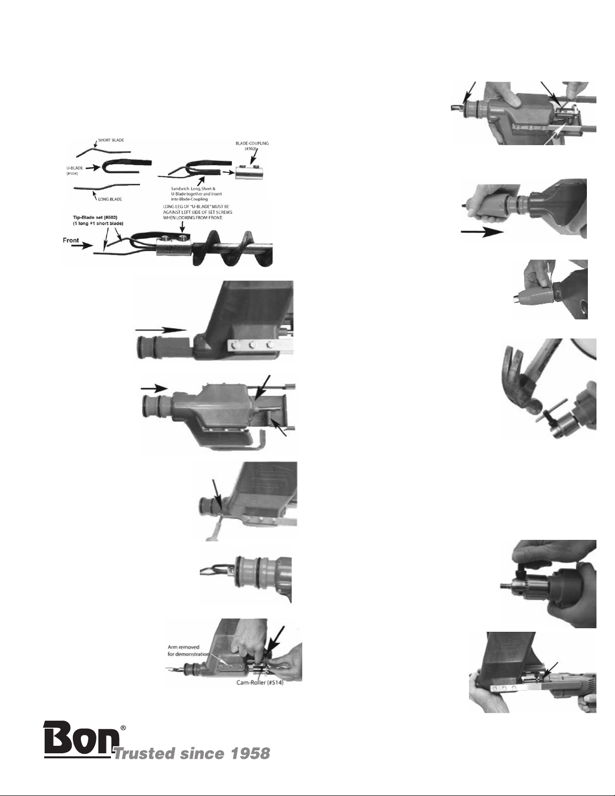
Tip bla es can be ma e from 1/8” electrician’s snake.
Ben with pliers an vice to contour below or sen for
replacement tips.
A set consists of one long, one short bla e an on “U” bla e.
<-- Insert this en in bla e coupling.
Caution: Protect eyes when cutting
har ene wire.
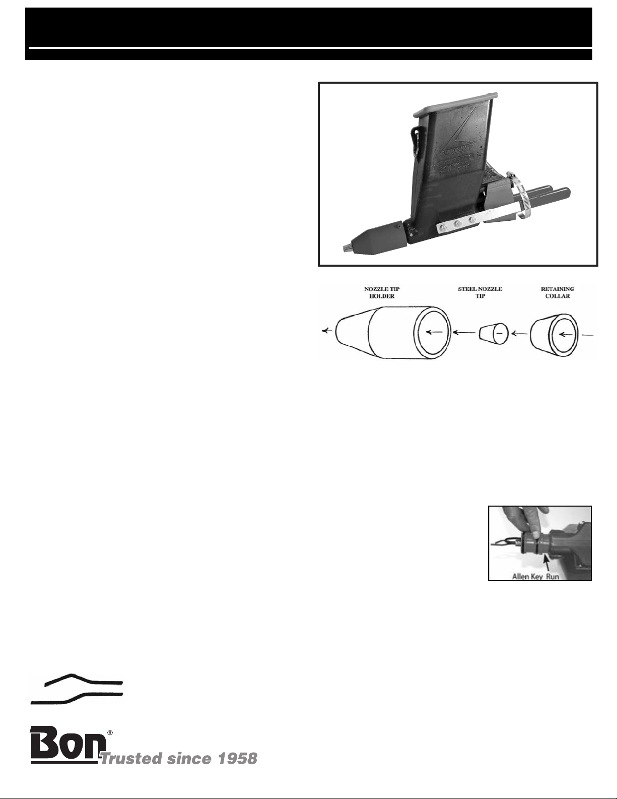
NOZZLE ASSEMBLY
1. Drop metal nozzle tip into nozzle tip hol er. Then insert
retaining collar as shown.
2. Slip the assembly over the front barrel of the gun. Pull the
nozzle assembly firmly against the front face of the gun
barrel until the metal nozzle tip is seate tightly in the
nozzle hol er.
3. Insert the allen wrench key into the holes at the back of the
nozzle assembly. The allen key, when properly place ,
will fit in the slot at the back of the secon o-ring.
Note: The nozzle assembly can now
be rotate for vertical or horizontal
applications. When assembling,
make sure all mating surfaces are
clean to insure proper seating. Put
lubricant such as Vaseline on o-ring
area an area where Allen Key runs.
AUGER ASSEMBLY
1. Install the Bla e-Coupling (#502) on to the Auger by
tightening the Socket set screw on the flat of the auger
shaft.
2. The short leg of the U-Bla e (#504) is inserte between the
Tip-Bla e-Set (#503) with the short-bla e above (so that the
set screw tightens on this bla e first) an the long bla e
below.
1
INSTRUCTIONS
#14-188 Quickpoint
4430 Gibsonia Rd. • Gibsonia, PA 15044 • USA • www.bontoo .com
IS14188 08/09
PAGE 1 OF 4