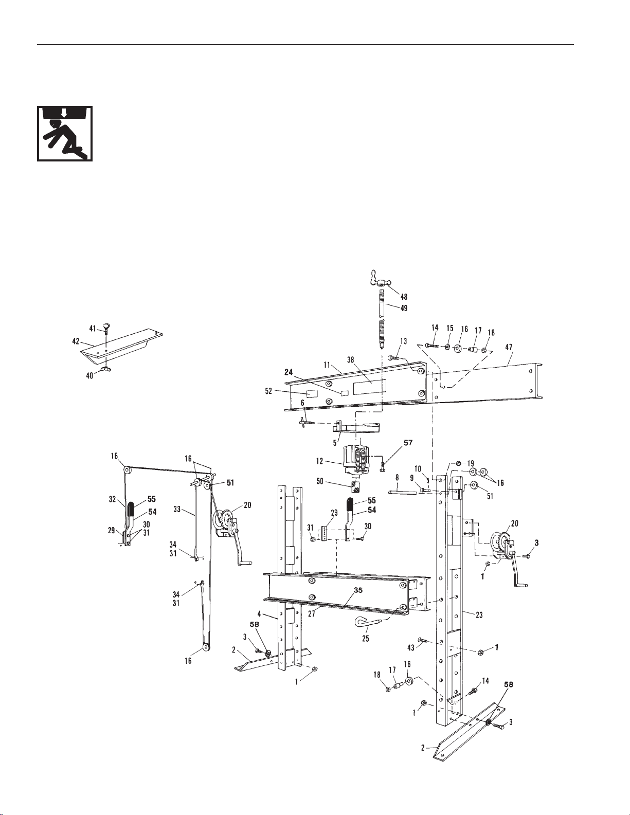
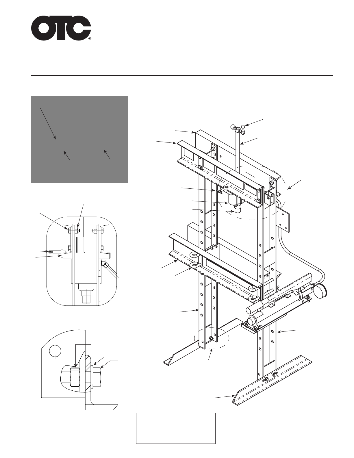
ASSEMBLY (This section includes instructions for installing the optional Winch Kit No. 211407.)
Remove the shipping banding that secures the press parts to the pallet. Then remove all cartons from the
pallet and verify the parts received against the parts list provided.
Note: During assembly of the press, only hand tighten the nuts and bolts. After the press is completely
assembled, wrench tighten all nuts and bolts.
1. Attach the foot angles (Figure 1, item 2) to the press uprights (Figure 1, items 23 and 4) using four ½-in.
cap screws (item 3), washers (item 58), and hex nuts (item 1).
Note: The bolster (item 27) must be positioned with the stamped number facing up and the protruding
bolster end toward the left side, as you face the unit.
2. Slide the uprights (item 4 on the left and item 23 on the right) into position and attach them to the lower
bolster (item 27) using four bolster pins (item 25).
3. With the stamped part number on the upper front bolster (item 11) facing down, attach the front bolster to
the uprights using four ⅞-in. cap screws (item 13) and hex nuts (item 19).
4. Insert the pulley axle (item 8) through the back hole in the top of the right-hand upright. Place two 2-in.
dia. pulleys (item 16) on the axle and then push the axle into the front hole in the upright.
Note: Lubricate the pulley axles using a general-purpose grease.
5. Attach the top, back bolster (item 47) to the upright using four ⅞-in. cap screws (item 13) and hex nuts
(item 19).
6. Attach a 2-in. dia. pulley (item 16) to the left side of the rear upper bolster using a spacer (item 17), a ½-in.
cap screw (item 14), a washer (item 15) and a ½-in. locknut (item 18).
7. Attach a 2½-in. dia. pulley (item 51) to the upper bracket of the right upright using a clevis pin (item 9) and
a cotter pin (item 10).
8. Attach a 2-in. dia. pulley (item 16) to the lower bracket of the right upright using a ½-in. cap screw (item
14), a spacer (item 17), and a ½-in. locknut (item 18).
9. Fasten two cable adjustment straps (item 29) to the spacer on the left end of the lower bolster (item 27)
using two ¼-in. cap screws (item 30) and ¼-in. locknuts (item 31).
10. Attach the winch and cable assembly (item 20) to the right-hand upright using two ⅜-in. cap screws (item
3) and nuts (item 1).
11. Route the short winch cable (item 33) as shown and attach it to the top right end of the lower bolster using
a ¼-in. cap screw (item 34) and ¼-in. locknut (item 31).
12. Fasten the clevis end of the long cable (item 32) to the bottom of the right end of the bottom bolster using
a ¼-in. cap screw (item 34) and ¼-in. locknut (item 31). Route the cable as shown.
Note: The adjustment strap (item 29) has a series of holes. For the following step, select the hole that
allows the cable eyelet to just reach the strap without requiring the bolster to be raised.
13. Attach the handle (item 54) to the cable adjustment strap (item 29) using a ¼-in. cap screw (item 30) and
¼-in. locknut (item 31), making sure to slide the eyelet on the end of the cable (item 32) onto the cap
screw before threading on the nut.
14. Completetheinstallation ofthe handleby installinga second¼-in. capscrew (item30)throughthe handle
and cable adjustment strap and securing it with a ¼-in. locknut (item 31).
Operating Instructions Form No. 102458