BOND MANUFACTURING RAPID INDUCTION AREA HEATER HYPH4601-12 User manual

3
RAPID INDUCTION AREA HEATER®
DANGER:
Do not store or use gasoline or other flammable vapors
and liquids in the vicinity of this or any other appliance.
A propane cylinder not connected
for use shall not be stored in the vicinity of this or any
other appliance.
WARNING:
Improper installation, adjustment, alteration,
service or maintenance can cause property damage,
injury or death. Read the installation, operating and
maintenance instructions thoroughly before installing
or servicing this equipment.
CARBON MONOXIDE HAZARD
This appliance can produce carbon monoxide which
has no odor. Using it in an enclosed space can kill you.
Never use this appliance in an enclosed space such as
a camper, tent, car or home.
WARNING: For Outdoor Use Only.
INSTALLER:
Leave this manual with the appliance.
CONSUMER:
Retain this manual for future reference.
DANGER:
IF YOU SMELL GAS:
1. Shut off gas to the appliance.
2. Extinguish any open flame.
3. If odor continues, keep away from the appliance and
immediately call your gas supplier or fire department.
DANGER
WARNING: FUELS USED IN LIQUEFIED
PROPANE GAS APPLIANCES,AND THE PRODUCTS
OF COMBUSTION OF SUCH FUELS, CAN EXPOSE
YOU TO CHEMICALS INCLUDING BENZENE, WHICH
IS KNOWN TO THE STATE OF CALIFORNIA TO CAUSE
CANCER AND CAUSE BIRTH DEFECTS OR OTHER
REPRODUCTIVE HARM.
For more information go to: www.P65Warnings.ca.gov.

4
SAFETY INFORMATION
WARNINGS:
Before you assemble or operate this unit, please carefully read this entire manual. Failure to do so may result in
a fire, explosion, injury or death.
1. The installation of this unit must adhere to local codes or Propane Storage and Handling Code, CSA B149.2.
2. THIS UNIT IS INTENDED FOR OUTDOOR USE ONLY! This product shall be used outdoors, in a ventilated
space and shall not be used in any enclosed area.
3. This unit is to be used with propane gas only! (sold separately)
4. Do not attach a remote gas supply to this unit.
5. Only use propane gas for this unit.
6. This unit is not intended for natural gas.
7. Converting this unit to natural gas is dangerous and not recommended. The conversion of this unit will void
the manufacturer warranty.
8. Do not use any solid fuel or charcoal for this unit.
9. If the propane gas tank is leaking gas, you may smell, see, or hear a hiss. Do the following:
1. Disconnect the propane gas tank.
2. Do not attempt to fix the problem yourself.
3. Contact your gas supplier or fire department for help.
10. Applying too much propane may result in gas pooling and will not burn. Allow fresh air into the unit so that
the remaining gas may escape.
11. Do not use a flame to check for gas leaks.
12. Manifold pressure: 11 in w.c. (2.74kPa).
13. Use propane tanks with the following dimensions: diameter 12 in, height 18 in. - capacity 20 lbs.
14. You must use a propane tank that has a collar to protect the gas valve.
15. DO NOT fill tank over 80 percent full.
16. The tank system must be set up for vapor withdrawal.
17. Discontinue use if any part of the propane tank is damaged. Rust and dents may be hazardous and should be
inspected by a gas supplier.
18. Do not operate unit until all parts are fully assembled.
19. Do not paint or color any part of this heating unit.
20. Unit may be hot while in use, do not attempt to move it while in use.
21. Never leave this heating unit unattended while in use.
22. This unit is not intended for cooking.
23. Keep any flammable items away.
24. Keep a safe distance to avoid burning skin or clothing.
25. Do not sit or rest hands or feet on this heating unit.
26. Never place hands or fingers on upper portion of this unit while in use.
27. Keep all electrical cords and fuel supply hose away from heated surfaces.
28. Combustible material should not be within 24 inches of the top of the unit, or within 24 inches around the
entire unit.
29. Keep the appliance area clear and free from combustible material, gasoline and other flammable vapors and
liquids.

5
SAFETY INFORMATION
30. If the flame goes out while burning, turn the gas valve off. Wait 5 minutes before repeating the initial lighting
procedure. Once you have a flame started, hold down the control knob for 1 minute.
31. Do not add water into the unit.
32. Do not operate unit if any part has been under water. Call a service technician to replace any damaged parts
should this occur.
33. Do not disconnect any part while unit is in use.
34. Do not store a spare propane tank under or near this appliance.
35. If the heating unit is indoors, detach the propane tank and leave outdoors.
36. Do not operate on a boat or vehicle. This unit must be used on a flat surface and outdoors ONLY.
37. Always remove protective cover before operating (if applicable).
38. Check for leaks after not using the unit for long periods of time.
39. Children should never operate this unit. Children must be supervised while near this unit.
40. Keep gas tank at least 5 feet away from unit when lit. (if external tank)
41. The maximum gas supply: 250psi; Min. gas supply: 10 psi.
42. All installation and repair should be done by a qualified professional. This unit should be inspected annually
and cleaned regularly.
43. Inspect all elements of this heating unit before each use. If there is damage, the burner must be replaced.
44. Be aware of the hazards of high temperatures and stay away from the unit to avoid any burns or injury.
45. The gas supply tank should be constructed and marked in accordance with the specifications for the LP-gas
cylinders of the U.S. Department of Transportation (DOT) or CSA B339;
46. The propane gas tank must have a listed overfilling prevention device and a QCCI or Type I, (CGA791) propane
gas tank connection.
47. This heating appliance should not be used on plastic or artificial wood decks.
48. Children and adults should be alerted to the hazards of high surface temperatures and should stay away to
avoid burns or clothing ignition.
49. Young children should be carefully supervised when they are in the vicinity of the heater.
50. Clothing or other flammable materials should not be hung from the heater, or placed on or near the heater.
51. Any guard or other protective device removed for servicing the appliance shall be replaced prior to operating
the heater.
52. Installation and repair should be done by a qualified service person. The heater should be inspected before
use and at least annually by a qualified service person. More frequent cleaning may be required as necessary.
It is imperative that the control compartment, burners and circulating air passageways of the heater be kept
clean.
53. Storage of an appliance indoors is permissible only if the cylinder is disconnected and removed from the
appliance. A cylinder must be stored outdoors in a well-ventilated area out of the reach of children. A
disconnected cylinder must have dust caps tightly installed and must not be stored in a building, garage or any
other enclosed area.
54. Place the dust cap on the cylinder valve outlet whenever the cylinder is not in use. Only install the type of dust
cap on the cylinder valve that is provided with the cylinder valve. Other types of caps or plugs may result in
leakage of propane.
55. Installation of this appliance at altitudes above 2000 ft (610 m) shall be in accordance with local codes, or in
the absence of local codes, ANSI Z223.1/NFPA 54 or CSA B149.1.
56. Appliance may shut down in windy conditions in excess of 3 miles per hour (4.83 kilometers per hour).
57. This appliance shall be used only in a well-ventilated space and shall not be used in a building, garage, or any
other enclosed area.
6
SAFETY INFORMATION
Only use the regulator and hose assembly provided with this unit. Replacement parts must be supplied parts by
the manufacturer.
Inspect the burner before use of this unit. If the burner shows any kind of damage, do not operate the appliance.
For assistance with repair or replacement of the burner or any other parts, call the manufacturer at 1-877-447-
4768
NOTE: You must follow all steps to properly assemble this heating item. Make sure the gas valve is turned ‘OFF’
before assembling. Do NOT attempt to assemble without proper tools.
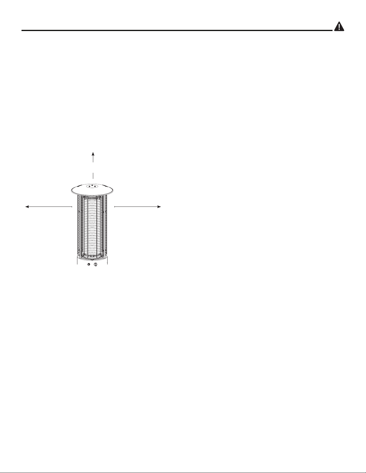
Combustible materials should not be within 24 inches of the
top of the unit, or within 24 inches around the entire unit.
24 in.
60.96 cm
24 in.
60.96 cm
24 in.
60.96 cm
BE CAREFUL:
When certain materials or items are stored above, beside or
under this heater while in use, they will be subject to radiant heat
and could be seriously damaged.
7
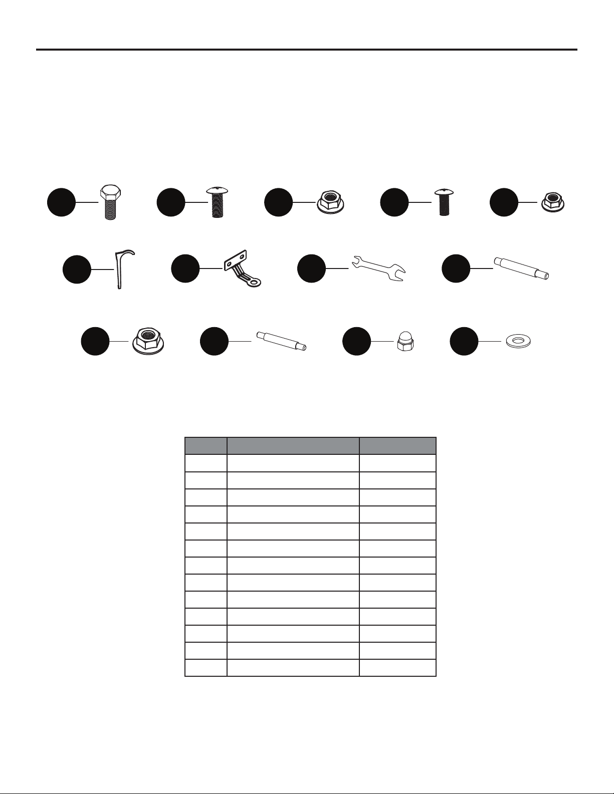
PART DESCRIPTION QTY
AA M8 x 16 Screw 2
BB M16 x 12 Screw 6
CC M6 Nut 6
DD M5 x 12 Screw 5
EE M5 Nut 5
FF Ancor 3
GG Anchoring Arm 3
HH Wrench 1
II M8 x 75 Stud 3
JJ M8 Nut 3
KK M6 x 60 Stud 3
LL M6 Cap Nut 3
MM M6 Washer 3
HARDWARE
AA BB CC DD EE
FF GG HH II
JJ KK LL MM
8
PART DESCRIPTION QTY
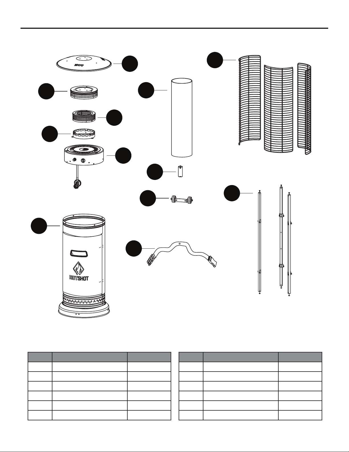
A Reflector 1
B Upper Radiation Screen 1
C Lower Radiation Screen 1
D Glass Tube Ring 1
E Burner 1
F Tank Housing 1
PACKAGE CONTENTS
PART DESCRIPTION QTY
G Glass Tube 1
H Mesh Guard 3
I Battery (AA) 1
J Wheel Assembly 1
K Upper Supporter 3
L Belt 1
B
D
E
F
C
A
G
I
J
L
H
K
9
PREPARATION
Before beginning assembly of product, make sure all parts are present. Compare parts with package contents list and
hardware contents above. If any part is missing or damaged, do not attempt to assemble the product. Contact customer
service for replacement parts.
Estimated Assembly Time: 30 minutes
Tools Required for Assembly (included): Wrench
Tools Required for Assembly (not included): Philips Screwdriver
NOTE: You must follow all steps to properly assemble this heating item. Make sure the gas valve is turned ‘OFF’ before
assembling. Do NOT attempt to assemble without proper tools.
ASSEMBLY INSTRUCTIONS
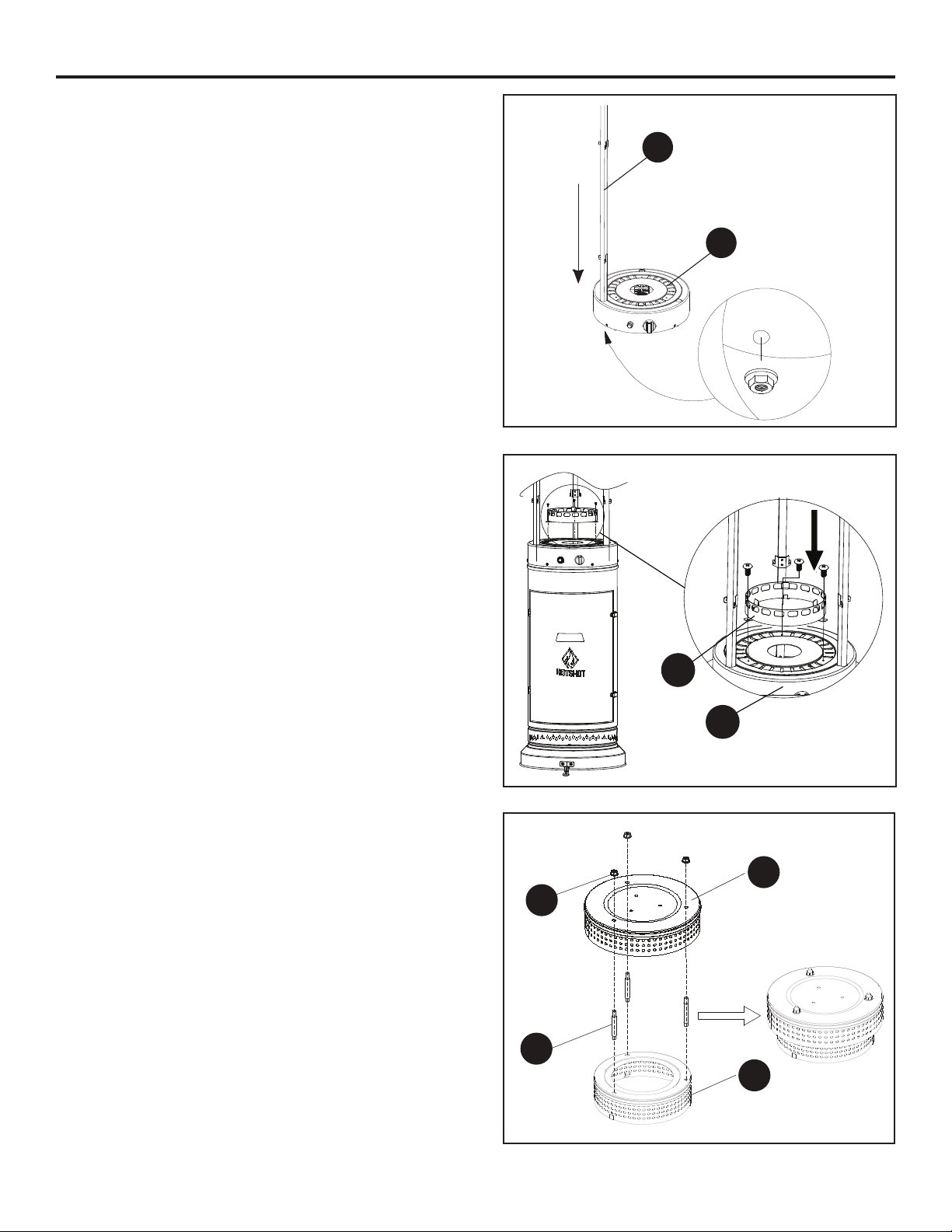
Step 1
Flip the tank housing (F) over and place gently on a
flat surface. Using 2 M6 x 16 screws (AA),attach the
wheel assembly (J) to the base of the tank housing (F).
Tighten with the included wrench (HH).
AA
F
J

10
Step 2
Attach the anchoring arms (GG) onto the base of the
tank housing (F) using 6 M6 x 12 screws (BB) and 6 M6
nuts (CC).
ASSEMBLY INSTRUCTIONS
Step 3
Flip over the tank housing (F) so that it is right-side
up. Attach the belt (L) to the tank housing (F) using 1
M5X12 screw (DD) and 1 M5 nut (EE).
Step 4
Align the holes at the bottom of the burner (E) to the
top of the tank housing (F). Make sure to position it so
that the control panel on the burner (E) is aligned with
the door on the tank housing (F). Insert 4 M5X12 screws
(DD) through the aligned screw holes and secure with 4
M5 nuts (EE). Tighten with the included wrench (HH).
GG
BB
CC
F
F
DD
EE
L
E
DD
EE
F
11
ASSEMBLY INSTRUCTIONS
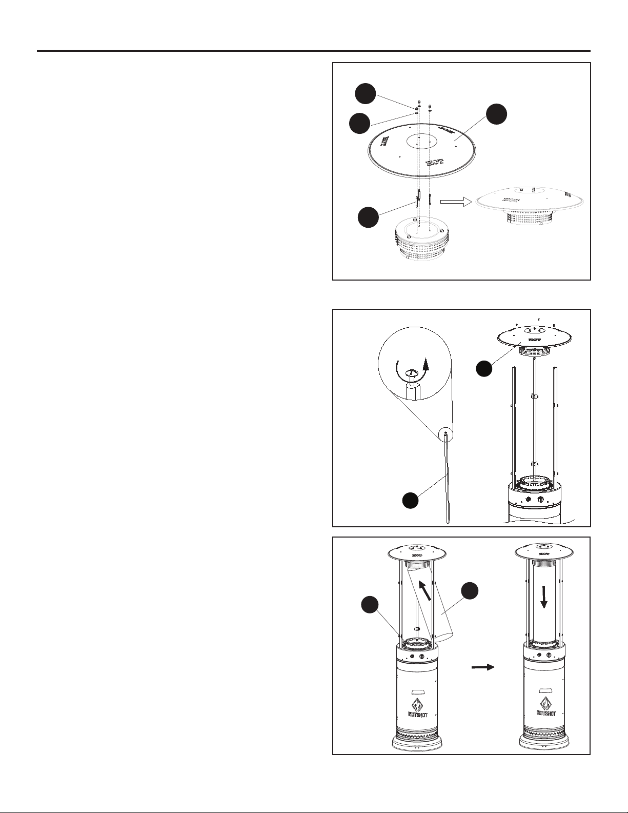
Step 7
Attach the upper radiation screen (B) to the lower
radiation screen (C) using 3 M8x75 studs (II) and 3 M8
nuts (JJ).
Step 5
Remove the 3 preassembled M5 nuts from the upper
support (K). Slide the 3 upper supports into the slots at
the top of the burner (E). Once fully inserted, secure the
upper supporters into the burner by reattaching the M5
nuts that were removed at the beginning of this step.
Step 6
Remove the 3 preassembled screws from the top of
the burner (E). Attach the glass tube ring (D) to the top
of the burner (E) using the 3 screws removed at the
beginning of this step. Tighten securely with a Phillips
screwdriver.
K
E
E
D
B
C
JJ
II
Note: The hooks on the upper supports (K) should be
facing up, as pictured.
12
Step 8
Attach the reflector (A) to the radiation screen
assembly using 3 M6x60 studs (KK), 3 M6 washers
(MM) and 3 M6 cap nuts (LL). Tighten with the included
wrench (HH).
ASSEMBLY INSTRUCTIONS
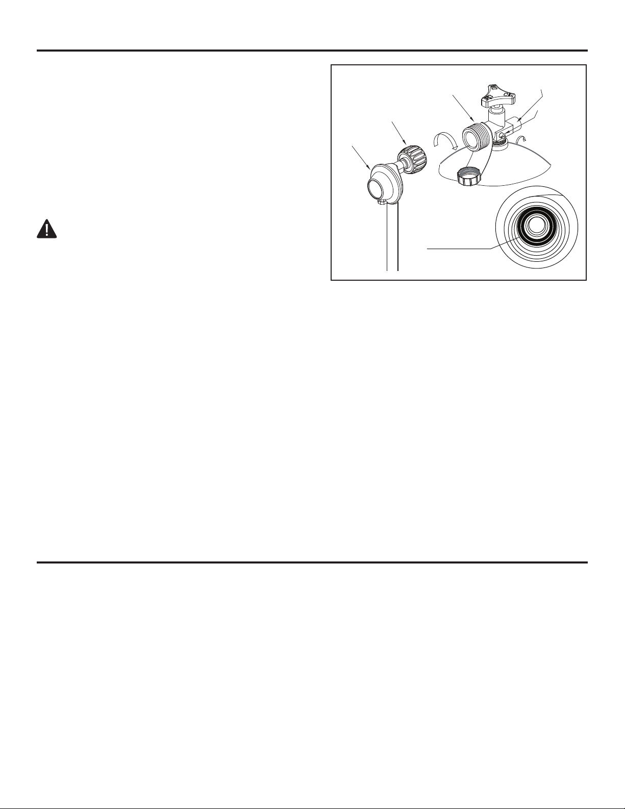
Step 9
Remove the 3 preassembled screws from the upper
supports (K). Place the reflector (A) onto the top
of the upper supports (K). Replace the 3 screws
removed at the beginning of this step to secure the
reflector (A) to the upper supports (K). Tighten with
a Phillips screwdriver.
Step 10
Carefully slide the glass tube (G) in between the upper
supports (K) and place on top of the glass tube ring (D).
A
kk
MM
LL
9
A
K
G
D

13
ASSEMBLY INSTRUCTIONS
Step 13
Open the door from the tank housing (F) and place a
propane gas tank (not included) into the preassembled
tank support. Tighten the belt (L) to ensure the
propane gas tank is fully secure. Note: Once the tank is
connected to the regulator in the next step, make sure
to close the door.
Step 11
Attach the 3 mesh guards (H) onto the hooks at the top
of the upper supports (K).
Step 12
Optional: Use the anchor (FF) to fasten the product to
the ground. At the base of the unit, insert the anchors
(FF) through the anchoring arms (GG) and into the
ground.
KH
FF
GG
F
L
14
ASSEMBLY INSTRUCTIONS
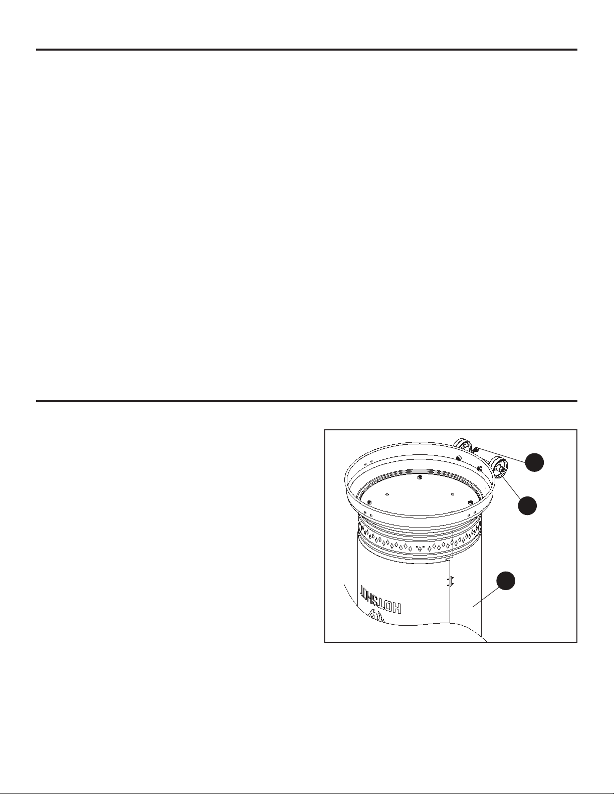
OPERATION
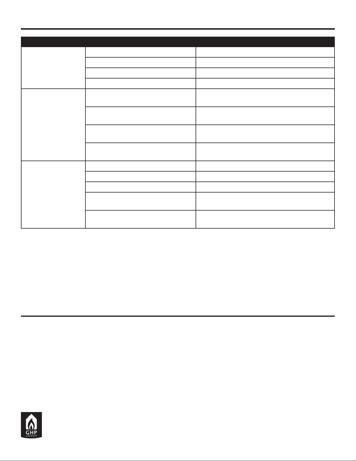
Step 14
Turn the cylinder valve on the tank clockwise to close
the propane tank. Attach the preassembled regulator to
the cylinder valve by turning the regulator coupling nut
clockwise. Make sure it is fastened securely and tighten
connections by hand only.
Before performing a leak test, be sure that no sparks can occur, and you are in a spacious outdoor area. Connect
the propane gas tank to the regulator and turn the valve on the unit to the “off” position. Brush a soap and water
mixture on all connections. Turn the gas supply on; if bubbles appear on any connection there may be a leak. If you
smell gas or a leak is discovered turn the gas valve off, disconnect the propane gas tank and do not use the appli-
ance until the leak is repaired.
1. The glass tube may break if it is wet while in use; never use the heater while it’s raining outside.
2. Do not splash any liquid on the heater while it is in use.
3. Keep children away from the unit while in use; the glass tube may be extremely hot while in use. Do not touch.
4. Ensure that the heater is on a strong and flat surface. The heater may be damaged if the unit tips over.
5. Never use the heater is the glass tube shows any cracks.
REGULATOR
BLACK COUPLING NUT
CYLINDER VALVE
PRESSURE
BLEED-OFF
VALVE
turn clockwise
to reseal
turn clockwise to connect
RELIEF VALVE
RUBBER O-RING
WARNING:
Please inspect the rubber O-ring in the propane tank valve to
ensure it is not worn before attaching regulator. Worn rubber
O-rings can cause leaks, explosions and serious injury by
propane tank.

15
OPERATION
CARE AND MAINTENANCE
• Before performing any maintenance always disconnect propane gas tank.
• Keep the heating item free and clear from combustible materials
• Visually inspect burner for obstructions and keep tank enclosure free and clear from debris.
• Use a soft brush to get rid of the mild stains, loose dirt and soil after the burner is completely cooled down.
Wipe down with a soft cloth.
• Harsh weather conditions may cause stubborn stains, discoloration, and possibly rust pitting.
• Permanent damage may occur if powder or solvent comes in contact with painted or plastic components on
this heating unit.
• Keep the heating unit stored away from direct sunlight.
• If storing this unit inside, disconnect the propane gas tank from the gas valve
• Not using manufacturer approved or supplied parts/accessories may result in a defective condition and void
the warranty of this heating unit.
• Carbon deposits may pose as a fire hazard; clean the reflector and inside of the glass tube with soap and water
if any carbon deposits are present.
WARNING:
If the burner does not ignite with the burner control valve
open, gas will continue to flow out of the burner and could
accidentally ignite causing injury or property damage.
To Light
1. Unscrew the ignition button on the burner to see if the battery (I) has already been placed inside. If the battery
(I) is not already within the ignition button on the burner, please place the battery (I) into the ignition button
slot.
2. Make sure the ignition control knob is turned to the ‘OFF’ position. Connect the propane gas tank and slowly
open the valve on the propane gas tank by turning the knob counterclockwise.
3. Press in and turn the ignition control knob to the ‘PILOT’ position; hold down for 1 minute.
4. Push the ignition button, while still holding down control knob down, to generate a spark.
5. Check to see if there is a pilot light through the glass tube (G). If there is, turn the control knob to the ‘LOW’
position.
6. For maximum flame height and heat output, turn the control knob to the ‘HIGH’ position.
To Extinguish
1. Push and turn the ignition control knob clockwise to the ‘OFF’ position.
2. Turn the propane gas tank valve on the gas tank to close the gas supply and disconnect the propane gas tank.
When lit for the first time the heater may emit a slight
odor and smoke. This is a normal and temporary con-
dition. The emitter screen will become a bright red due
to the heat. The color is more visible at night. Flame
patterns should be a blue flame; these flames should
not be yellow in color; indicating an obstruction of
airflow through the burners.
16
1-YEAR LIMITED WARRANTY
TROUBLESHOOTING
If within one year from the date of original purchase, this item fails due to a defect in material or workmanship, we
will replace or repair at our option, free of charge.
To order parts or to obtain warranty service, call 1-877-447-4768, 8:00 a.m. - 4:30 p.m., CST, Monday - Friday. Or
This warranty does not cover defects resulting from improper or abnormal use, misuse, accident, or alteration.
Failure to follow all instructions in the owner’s manual will also void this warranty. The manufacturer will not be
liable for incidental or consequential damages, or common erosion of outdoor products. Some states do not allow
the exclusion or limitation of incidental or consequential damages, so the above limitation may not apply to you.
This warranty gives you specific legal rights, and you may also have other rights which vary from state to state.
GHP Group Inc.
6440 W. Howard St.
Niles, IL 60714-3302
877-447-4768
Problem Possible Cause Solution
Pilto won't Light
Gas valve may be off Turn the gas valve on
Gas tank may be empty Refill the gas tank
Orifice may be blocked Clean out the orifice
Air is within supply system Pump out air from all lines
Pilot won't stay on
Loose connection Check all fittings and tighten connections as
necessary
Loose connection Check all fittings and tighten connections as
necessary
Thermocouple is bad Call for a replacement part and replace the
thermocouple
Gas leak within the line Check all connections; call for a replacement part
if anything is damaged
Burner won't light
Lack of gas pressure Gas tank is almost empty
Orifice may be blocked Clean out the orifice
Control knob isn’t on Turn the control knob on
Thermocouple is bad Call for a replacement part and replace the
thermocouple
Pilot light assembly is bent or not in
the correct location
Place pilot light in the correct location and retry
lighting procedure

17
For replacement parts, call our customer service department at 1-877-447-4768, 8:00 a.m. – 4:30 p.m., CST,
Monday – Friday. Or contact customerservice@ghpgroupinc.com
REPLACEMENT PARTS LIST
Printed in China
B
D
E
F
C
A
G
I
J
L
H
K
PART DESCRIPTION Part #
A Reflector 30-01-661
B Upper Radiation Screen 30-01-662
C Lower Radiation Screen 30-01-663
D Glass Tube Ring 30-01-664
E Burner 30-01-665
F Tank Housing 30-01-666
G Glass Tube 30-01-667
H Mesh Guard 30-01-668
I Battery (AA) 30-01-669
J Wheel Assembly 30-01-670
K Upper Supporter 30-01-671
L Belt 30-01-672
AA-MM Hardware Pack 30-09-576
Table of contents
Other BOND MANUFACTURING Heater manuals


Popular Heater manuals by other brands


Zodi
Zodi Hot Vent 9173 instructions

Lakeland
Lakeland DRY SOON 53343 Instruction booklet

Hakko Electronics
Hakko Electronics 853 quick guide

Riello
Riello NUOVO ACU Series TECHNICAL INFORMATION ASSEMBLY, USE AND MAINTENANCE INSTRUCTIONS

Mars Air Systems
Mars Air Systems STD2 Unheated Series manual

Honeywell
Honeywell UberHeat HCE200 Series user manual