bonitron M3660REM User manual
Web: www.bonitron.com ● Tel: 615-244-2825 ● Email: info@bonitron.com
Model M3660REM
Regenerative Energy Monitor
Customer Reference Manual

Bonitron, Inc.
2
Bonitron, Inc.
Nashville, TN
An industry leader in providing solutions for AC drives.
ABOUT BONITRON
Bonitron designs and manufactures quality industrial electronics that improve the reliability of
processes and variable frequency drives worldwide. With products in numerous industries, and
an educated and experienced team of engineers, Bonitron has seen thousands of products
engineered since 1962 and welcomes custom applications.
With engineering, production, and testing all in the same facility, Bonitron is able to ensure its
products are of the utmost quality and ready to be applied to your application.
The Bonitron engineering team has the background and expertise necessary to design, develop,
and manufacture the quality industrial electronic systems demanded in today’s market. A strong
academic background supported by continuing education is complemented by many years of
hands-on field experience. A clear advantage Bonitron has over many competitors is combined
on-site engineering labs and manufacturing facilities, which allows the engineering team to have
immediate access to testing and manufacturing. This not only saves time during prototype
development, but also is essential to providing only the highest quality products.
The sales and marketing teams work closely with engineering to provide up-to-date information
and provide remarkable customer support to make sure you receive the best solution for your
application. Thanks to this combination of quality products and superior customer support,
Bonitron has products installed in critical applications worldwide.

Bonitron, Inc.
3
AC DRIVE OPTIONS
In 1975, Bonitron began working with AC inverter drive specialists at synthetic fiber plants to
develop speed control systems that could be interfaced with their plant process computers. Ever
since, Bonitron has developed AC drive options that solve application issues associated with
modern AC variable frequency drives and aid in reducing drive faults. Below is a sampling of
Bonitron’s current product offering.
WORLD CLASS PRODUCTS
Undervoltage Solutions
Overvoltage Solutions
Uninterruptible Power for Drives
(DC Bus Ride-Thru)
Voltage Regulators
Chargers and Dischargers
Energy Storage
Braking Transistors
Braking Resistors
Transistor/Resistor Combo
Line Regeneration
Dynamic Braking for Servo Drives
Common Bus Solutions
Portable Maintenance Solutions
Single Phase Power Supplies
3-Phase Power Supplies
Common Bus Diodes
Capacitor Formers
Capacitor Testers
Power Quality Solutions
Green Solutions
12 and 18 Pulse Kits
Line Regeneration

M3660REM
4
This page intentionally left blank.

Table of Contents
5
1. INTRODUCTION ..........................................................................................................................7
1.1. Who Should Use ........................................................................................................................... 7
1.2. Purpose and Scope ........................................................................................................................ 7
1.3. Manual Version and Change Record ............................................................................................ 7
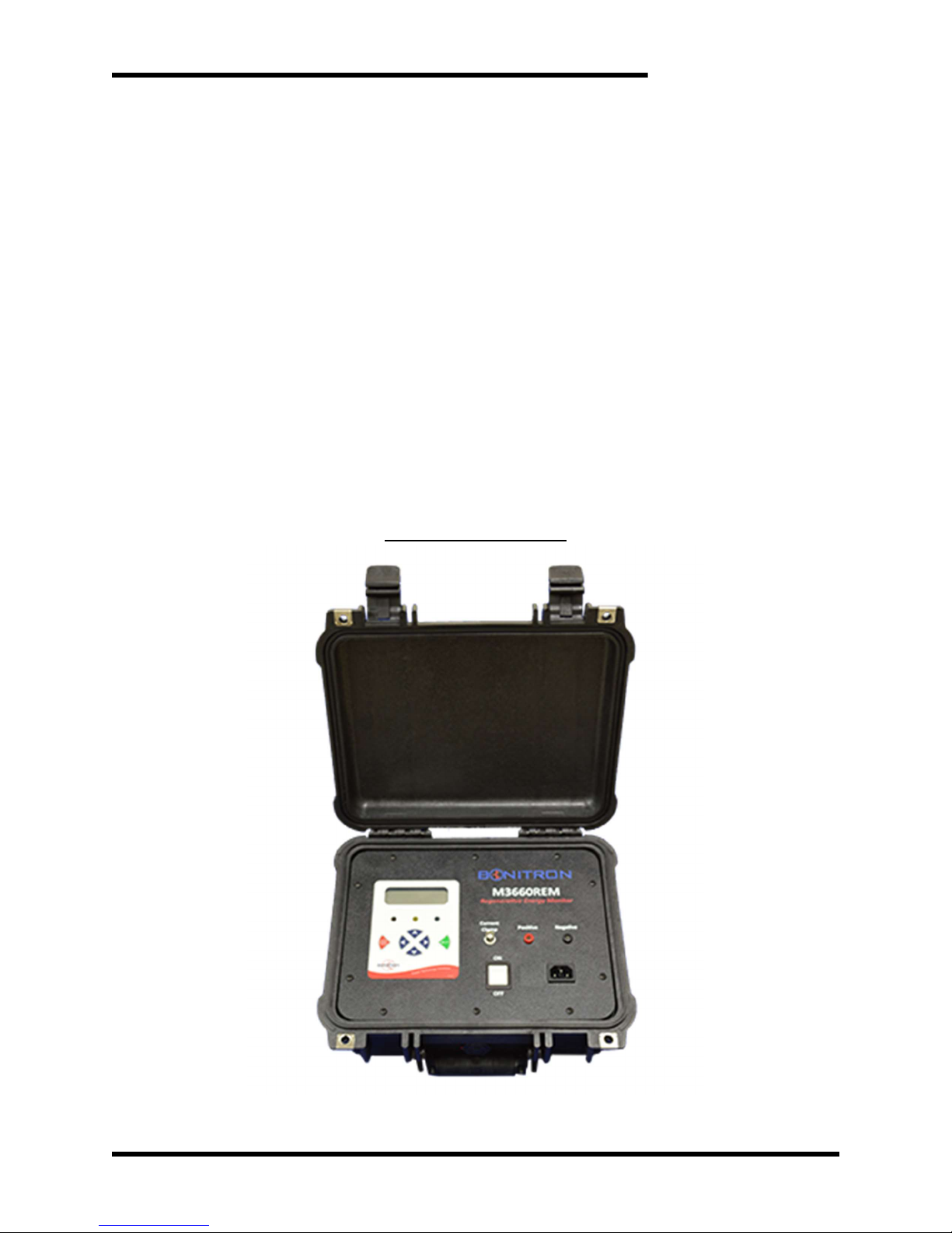
Figure 1-1: M3660REM.............................................................................................................. 7
1.4. Symbol Conventions Used in this Manual and on Equipment ..................................................... 8
2. PRODUCT DESCRIPTION / FEATURES ........................................................................................9
2.1. Related Products ........................................................................................................................... 9
2.2. Part Number Breakdown ............................................................................................................ 10
Figure 2-1: Example of Part Number Breakdown .................................................................... 10
Table 2-1: System Voltage ........................................................................................................ 10
2.3. General Specifications ................................................................................................................ 11
Table 2-3: General Specifications Table ................................................................................... 11
2.4. General Precautions and Safety Warnings ................................................................................. 12
3. INSTALLATION INSTRUCTIONS ................................................................................................13
3.1. Environment ............................................................................................................................... 13
3.2. Wiring and Customer Connections ............................................................................................. 13
4. OPERATION ..............................................................................................................................15
4.1. Functional Description ............................................................................................................... 15
4.2. Features ....................................................................................................................................... 16
4.2.1. Hardware .............................................................................................................................. 16
Figure 4-1: Cables ..................................................................................................................... 16
4.2.2. Display ................................................................................................................................. 17
Figure 4-2: Front Panel ............................................................................................................. 17
4.2.3. Screens & Menu Navigation ................................................................................................ 18
Figure 4-3: Menu Tree .............................................................................................................. 19
5. TROUBLESHOOTING ................................................................................................................20
Table 5-1: Troubleshooting ....................................................................................................... 20
6. ENGINEERING DATA ................................................................................................................22
6.1. Ratings Chart .............................................................................................................................. 22
Table 6-1: Ratings Chart ........................................................................................................... 22
Table 6-2: Dimensions .............................................................................................................. 22

M3660REM
6
This page intentionally left blank.
User’s Manual
7
1. INTRODUCTION
1.1. WHO SHOULD USE
This manual is intended for use by trained personnel responsible for integrating,
installing, maintaining, troubleshooting, or using this equipment with any AC drive
system.
Please keep this manual for future reference.
1.2. PURPOSE AND SCOPE
This manual is a user’s guide for the model M3660REM. It will provide the user with
the necessary information to successfully connect and operate the M3660REM.
In the event of any conflict between this document and any publication and/or
documentation related to any associated hardware (capacitor bank, etc.), the latter
shall have precedence.
1.3. MANUAL VERSION AND CHANGE RECORD
The initial release for this module is Rev 00a.
Figure 1-1: M3660REM

M3660REM
8
1.4. SYMBOL CONVENTIONS USED IN THIS MANUAL AND ON
EQUIPMENT
Earth Ground or Protective Earth
AC Voltage
DC Voltage
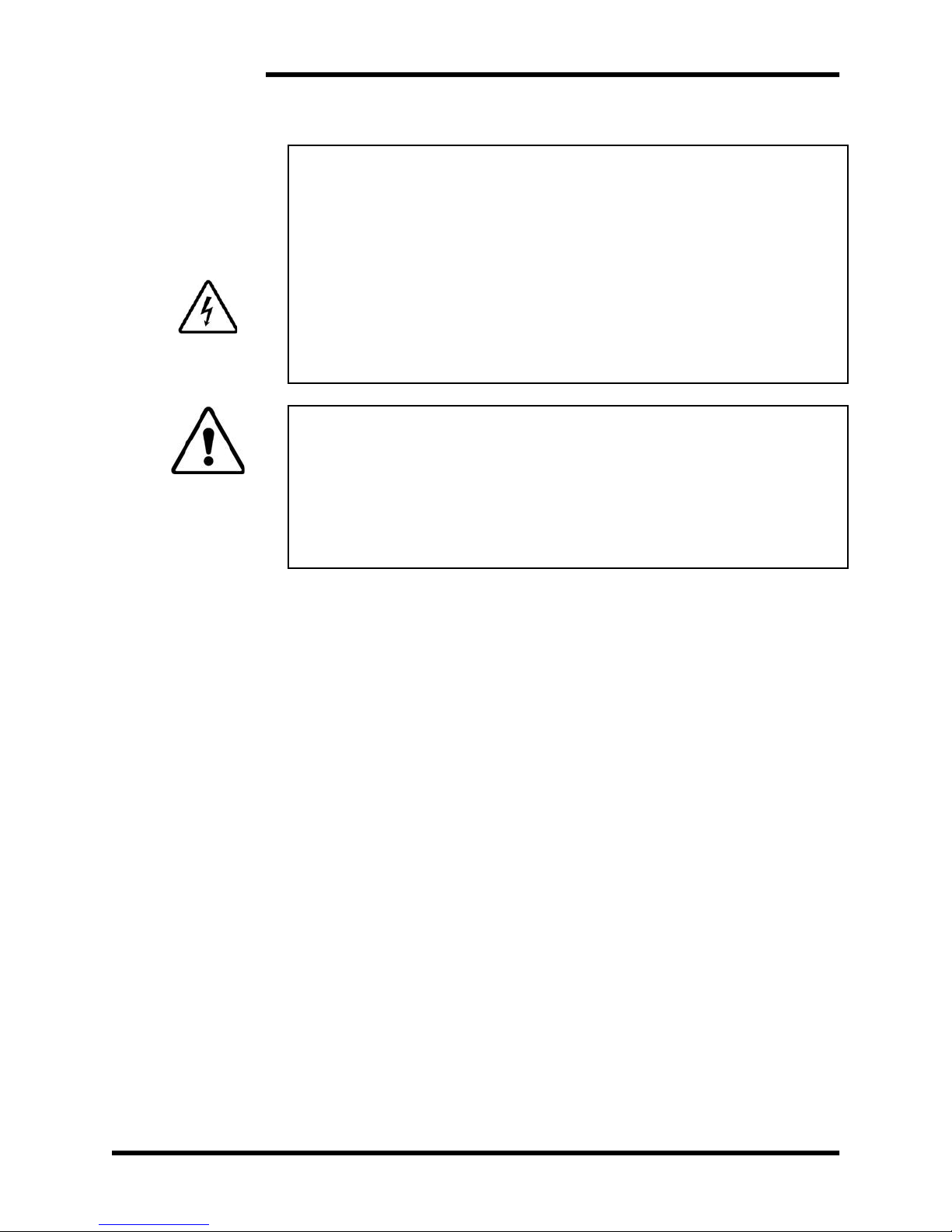
DANGER!
DANGER: Electrical hazard - Identifies a statement that indicates
a shock or electrocution hazard that must be avoided.
DANGER!
DANGER: Identifies information about practices or circumstances
that can lead to personal injury or death, property damage, or
economic loss.
CAUTION!
CAUTION: Identifies information about practices or circumstances
that can lead to property damage, or economic loss. Attentions
help you identify a potential hazard, avoid a hazard, and
recognize the consequences.
CAUTION!
CAUTION: Heat or burn hazard - Identifies a statement regarding
heat production or a burn hazard that should be avoided.

User’s Manual
9
2. PRODUCT DESCRIPTION / FEATURES
The Bonitron M3660 Regenerative Energy Monitor is a system analysis tool designed to
assist system integrators and end users in the proper sizing of their braking solution:
whether that’s optimizing an existing resistive solution or replacing it with a regenerative
one.
The M3660REM monitors the voltage and current seen by the load resistor; this allows it
to characterize a braking Event by measuring the peak and average currents as well as
calculating the total energy in the Event. This can be helpful information for system
engineers to verify that the braking chopper and/or load resistor are appropriately sized
and rated for the requirements of the application.
2.1. RELATED PRODUCTS
BRAKING TRANSISTORS
M3575T – Standard Duty Braking Transistor (up to 600A)
M3452 – Heavy Duty Braking Transistor (up to 1600A)
BRAKING RESISTORS
M3575R – Standard Duty Braking Resistors (up to 30A)
M3775R – Various Duty Load Banks (up to 1600A)
REGENERATIVE BRAKING
M3545 – Single or 3- Phase Line Regen (up to 15A)
M3645 – Three Phase Line Regen (up to 300A)

M3660REM
10
2.2. PART NUMBER BREAKDOWN
Figure 2-1: Example of Part Number Breakdown
BASE MODEL NUMBER
The base model number for all Regenerative Energy Monitors is M3660REM.
SYSTEM VOLTAGE RATING
The System Voltage rating indicates the maximum AC system voltage for which the
unit is designed to operate.
Table 2-1: System Voltage
RATING CODE SYSTEM VOLTAGE
C Up to 600VAC
MAX CURRENT RATING
The max current rating indicates the maximum DC load current the unit can measure.
M3660REM
C
BAS E MODE L NU MB E R
SYST E M VOL T A GE CO D E
MAX CURRE N T RAT I N G
2000

User’s Manual
11
2.3. GENERAL SPECIFICATIONS
Table 2-3: General Specifications Table
PARAMETER SPECIFICATION
System Voltage Up to 600 VAC
Braking Current 200A / 2000A DC
Controls Six display soft keys
Display Four line, eighty character LCD (4x20)
Unit Size (H x W x D) 13.4" x 11.6" x 6.0"
Weight 6 lbs.
Storage Temp -20°C to + 65°C
Humidity Below 90% non-condensing
Atmosphere Free of corrosive gas and conductive dust
M3660REM
12
2.4. GENERAL PRECAUTIONS AND SAFETY WARNINGS
ELECTROCUTION
HAZARD!
FOR USE BY QUALIFIED AND TRAINED PERSONNEL ONLY!
IMPROPER OPERATION OF THE PRODUCT OR
IGNORING THESE WARNINGS MAY RESULT IN
SERIOUS BODILY INJURY OR DEATH!
BEFORE CONNECTING THE M3660REM TO A
BRAKING
RESISTOR TERMINALS, ENSURE THAT THE SYSTEM IS
POWERED
OFF.
NEVER OPERATE THIS PRODUCT WITH THE E
NCLOSURE COVER
REMOVED.
DANGER!
NEVER ATTEMPT TO SERVICE THIS PRODUCT.
CERTAIN PARTS INSIDE THIS PRODUCT MAY GET HOT DU
RING
OPERATION.
BEFORE CONNECTING THIS DEVICE TO ANY OTHER PRODUCT,
BE
SURE TO REVIEW ALL DOCUMENTATION OF THAT PRODUCT
FOR
PERTINENT SAFETY PRECAUTIONS
.
ANY QUESTIONS AS TO APPLICATION, INSTALLATION, OR SERVICE
SAFETY SHOULD BE DIRECTED TO THE EQUIPMENT SUPPLIER.

User’s Manual
13
3. INSTALLATION INSTRUCTIONS
3.1. ENVIRONMENT
While closed, the M3660REM is water, dust, and crush resistant. When open and in
operation, the unit should be used only in dry, clean areas. Ensure that the interior of
the unit casing is kept dry.
3.2. WIRING AND CUSTOMER CONNECTIONS
The M3660REM is not intended for permanent installation into a drive cabinet; it was
designed as a portable unit, to be used as needed. Therefore, it has no installation
wiring requirements.

M3660REM
14
This page intentionally left blank.

User’s Manual
15
4. OPERATION
4.1. FUNCTIONAL DESCRIPTION
The M3660REM is an analysis tool to help system designers get a better
understanding of the characteristics of their braking Events. It should be attached to
the load resistor terminals, not to the DC Bus directly; this way it only measures the
actual braking energy.
The REM records the following information about each braking Event it detects:
Date The Date that the Event occurred: YYYY:MM:DD
Time Time of Day when the Event occurred: HH:MM:SS
Length Duration of the Event: MM:SS.ms
Energy The total Energy dissipated during the Event (in kJ)
Avg Current The Average Current over the entire Event
Peak Current The Maximum Current reached during the Event
Note: the max save Length of a single saved Event is 30min; if an Event lasts longer
than this limit, it will automatically be split over multiple entries. For example, assume
a braking Event that lasted 42m, 27s. This will be saved as 2 Events: the first with a
Length of 30mins and the second with a Length of 12m, 27s.
In addition to the individual Event records, the Regen Monitor keeps some running
Lifetime Totals:
Number of Events
Total number of Events that have been recorded
Total Duration Total Duration of all recorded Events
Avg Duration Average Duration per Event, based on all recorded Events
Total Energy Total Energy from all recorded Events (in kJ)
Avg Energy Average Energy per Event, based on all recorded Events (in
kJ)
Peak Current Average of the Peak Current values from all recorded Events
Avg Current Average Current per Event, based on all recorded Events

M3660REM
16
4.2. FEATURES
4.2.1. HARDWARE
4.2.1.1. AC POWER INPUT CONNECTOR
The M3660REM is equipped with a standard IEC C14 connector for input
power. This connector mates with a standard C13 cable, commonly used
with desktop computers, to provide power to the unit.
4.2.1.2. VOLTAGE LEADS
The two voltage cables feature a large claw for easy connection to the
load terminals with a finger-safe, 4mm banana plug termination at the
unit.
4.2.1.3. CURRENT CLAMP
The provided Pico TA167 200A/2000A Current Probe connects to the
BNC terminal on the front panel of the unit.
Figure 4-1: Cables

User’s Manual
17
4.2.2. DISPLAY
The digital display presents the user with information about the present status
of the system, including the voltage and current. The display also presents
the user with options to control system operation.
4.2.2.1. DIRECTIONAL BUTTONS
Each of the four buttons corresponds to a direction: up, down, left or right.
Up and Down move the cursor among menu items. On screens where
numbers are input by the user, the Left and Right buttons move the
cursor, while the Up and Down buttons change the selected digits. On
some screens, certain buttons may have no function at all.
4.2.2.2. ENTER AND CANCEL BUTTON
The green Enter button selects menu options. On a menu screen, the red
Cancel button will return you to the previous menu.
Figure 4-2: Front Panel
M3660REM
18
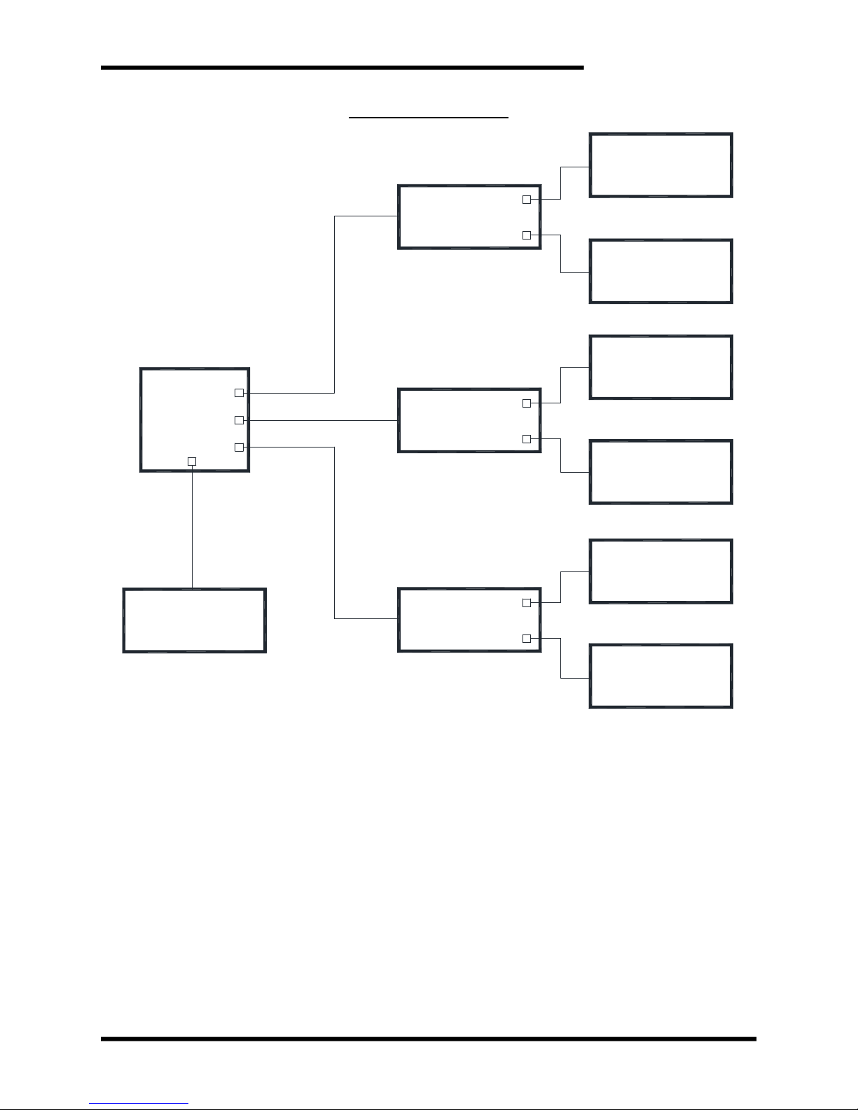
4.2.3. SCREENS & MENU NAVIGATION
Many screens are menus allowing access to other screens, or lists presenting
a number of options. The presently selected item on the menu is indicated by
a ‘>’ cursor. This selection indicator is moved using the Up and Down buttons.
If a line on the menu represents another screen, that screen is accessed with
the Enter button. The Cancel button will return the display to the parent
screen.
4.2.3.1. MAIN MENU
4.2.3.1.1. RECORDS
The Records Menu allows the user to view all saved Event
information. The Events page shows the most recent 50 Events in
chronological order. The Lifetime Stats page shows the
aggregated totals of all Events (since the last reset).
4.2.3.1.2. CONFIGURATION
The Configuration Menu contains all the settings that are user
adjustable.
Set Date/Time: The user can adjust the full timestamp (Year-
Month-Day, Hour-Minute-Seconds) if ever necessary.
Set Current Clamp: The user can swap between 200A and 2000A
settings.
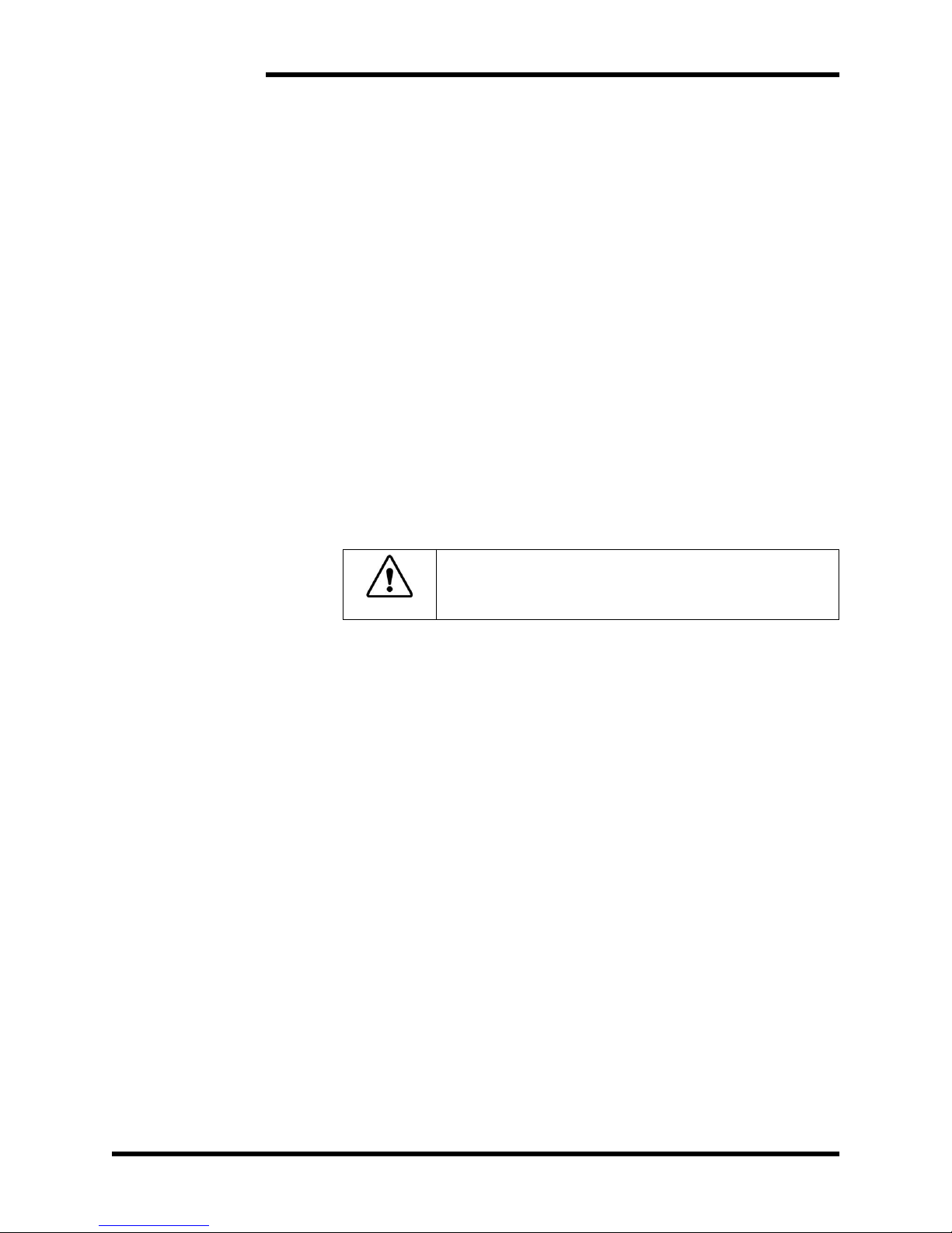
Important
!
The Clamp setting in the unit MUST match the
Range selector on the Pico probe, otherwise the
Current and Energy calculations will be incorrect.
4.2.3.1.3. CLEAR RECORDS
The user can manually erase the saved Event data if desired.
Clear Event Records – This option will erase only the individual
Events list. The Lifetime Stats will remain unaffected.
Clear All Data – This will erase ALL Event data, both the individual
Events as well as the Lifetime totals.
4.2.3.2. STATUS
This screen shows the general status of the unit. While an Event is being
recorded, it will show live data: braking voltage & current and the percent
loading.
User’s Manual
19
Figure 4-3: Menu Tree
Main
Menu
Clear
Records
Status
Configuration
Records
Individual
Events
Lifetime
Stats
Set
Date/Time
Set Current
Clamp
Clear Event
Records
Clear All
Data

M3660REM
20
5. TROUBLESHOOTING
If a problem occurs on start-up or during normal operation, refer to the problems described
below. If a problem persists after following the steps below, contact the product supplier
or your system integrator for assistance.
Repairs or modifications to this equipment are to be performed by Bonitron approved
personnel only. Any repair or modification to this equipment by personnel not approved
by Bonitron will void any warranty remaining on this unit.
Table 5-1: Troubleshooting
Display never comes on Ensure that the input power cable is connected firmly to the unit
and to a functioning power source at the correct voltage.
If both connections and the power supply are good, make sure
the input circuit breaker has not tripped.
Unit never goes ACTIVE
when a Braking Event occurs
Check the Voltage cables. Ensure they are firmly connected
between the unit and the load and that the polarity is correct.
Incorrect values for the Event
Currents and/or Energy are
being recorded
Check the Current Clamp. Verify that the twist-lock connector is
firmly seated on the front panel and Clamp’s jaws are closed
around the load wires.
Make sure the Current Clamp is powered ON and set to the
appropriate range.
Verify that the Current Clamp setting in the unit matches the range
selector on the Clamp.
Table of contents


