bonitron M3460R User manual

521 FAIRGROUND COURT •NASHVILLE, TENNESSEE 37211 •(615) 244-2825 •FAX (615) 244-2833
M3460R-4CAB1-150A2 (A4)
460VAC/150KW Ride-Thru Cabinet
System with PLC Interface and Metering,
& Single or Dual Totalizers
Customer Reference Manual

D3460R.CMAN.V4CAB1150AX.02
7/26/2000
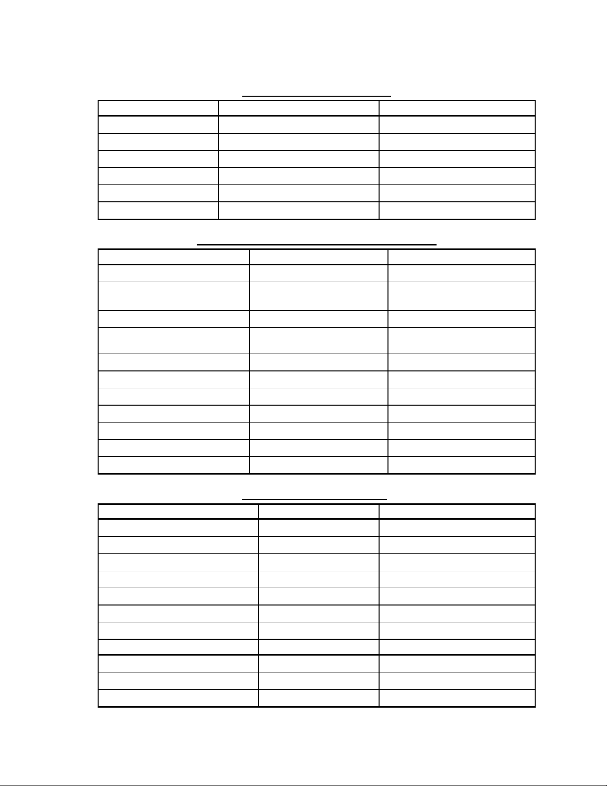
TABLE OF CONTENTS
Description Doc.# (Rev. Date)
Pg
Model M3460R Cabinet Mounted Ride-Thru System Operation Manual 993014 (07/25/00)
2
Model M3460R Ride-Thru Inductive Boost Circuit Theory Of Operation 003002 (01/12/00)
8
Inspection And Unpacking Instructions 990078 (08/03/99)
10
Field Installation Procedure For Rack Systems 993002 (10/22/99)
11
Conduit Access Modification Details 990163 (08/04/99)
12
Recommended Input Power Wiring Sizes And Power Source Fusing For Model M3460R Cabinet
Mounted Ride-Thru Systems 993004 (07/18/00)
13
Field Start-up Procedure For Rack Systems 993001 (10/22/99)
14
Ride-Thru Power Threshold Voltage Adjustment Procedure 985001 (07/21/00)
16
Ride-Thru Module Individual Stage Verification Procedure 993003 (06/29/00)
19
Typical Ride-Thru Cabinet Features and Dimensional Outline 000200 (07/13/00)
20
Option “A2” Display Panel Dimensional Outline and Layout Drawing 970066P (12/30/99)
21
Option “A4” Display Panel Dimensional Outline and Layout Drawing 980265P (12/30/99)
22
Ride-Thru Rack Disconnect Panel Layout 990255 (10/22/99)
23
Typical “R1” Chassis Ride-Thru Module With Metering and PLC Interface Dimensional Outline 990256 (10/22/99)
24
Typical Ride-Thru Cabinet Customer Connections and Internal Component ID Drawing 000199 (07/12/00)
25
Basic Ride-Thru and Inverter Power Interconnection 000122 (04/25/00)
26
Example of Shunt Trip Coil Wiring 990009 (06/20/00)
27
Example of Fault Output Wiring 990036 (08/27/99)
28
Ride-Thru Rack Disconnect Panel Wiring Diagram 970104 (10/25/99)
29
Option “A2” Display Panel and Status Monitor PLC Interface Wiring 970103 (10/28/98)
30
Option “A4” Display Panel and Status Monitor PLC Interface Wiring 990026 (10/21/99)
31
(M3460R-4R1-150C2) 460VAC/150KW Ride-Thru Module Control Wiring Diagram 990243 (07/12/00)
32
(M3460R-4R1-150C2) 460VAC/150KW Ride-Thru Module Power Section Wiring Diagram 990244 (07/12/00)
33
Typical Ride-Thru Cabinet System Basic Signal Flow Diagram 990259 (12/30/99)
34
Typical Ride-Thru Cabinet System Diagnostic Signal Connections Diagram 980233 (07/25/00)
35
Ride-Thru Module Removal Information for Service or Replacement 970200 (07/18/00)
36

Doc.# 993014
07/25/2000
BONITRON
M3460R-4CAB1-1XXA2 (A4) RIDE-THRU
OPERATION MANUAL
1. Overview
This document describes a rack mounted Ride-Thru module used to provide the DC bus power for multiple
AC PWM inverter drives during a power line dip or phase loss situation.
The Ride-Thru module is factory set to become active (begin supplying power) if the DC bus voltage drops to
a preset level. The Ride-Thru module is designed to operate at its rated load for 2 seconds under the following
conditions:
•A 50% dip in the line voltage on all 3 phases, or
•A single-phase loss with the other 2 phases at remaining at the rated voltage.
The Ride-Thru module’s power rating (kW) must equal that of the drive(s) being supplied by the module with
a 2 second 2X surge capability.
The Ride-Thru module is designed to operate continuously, 24 hours per day, 365 days per year.
2. Specifications
GENERAL SPECIFICATIONS
PARAMETER SPECIFICATION
Input AC Line Voltage 460VAC ±10%, 3 phase, 50/60 Hz
Output DC Bus Voltage 640VDC nominal, 590VDC minimum
Inactive Power Consumption < 100 Watts
Ride-Thru Requirement 50% dip of all 3 phases, Duration: 120 cycles (2 sec.), or
100% loss of single phase, Duration: 120 cycles (2 sec.)
AC Voltage Dip setpoint Factory set to 410VAC
DC Bus Dip Setpoint Factory set to 590VDC (Adjustable from 525-625VDC)
Low Bus Fault Setpoint Factory set to 565VDC
Packaging Rack Mounted (600mm x 800 mm x 2000mm)
Disconnect Disconnect actuator located on front of rack
Mechanically interconnected 3∅AC line and DC bus breakers
120VAC Shunt trip coil on all breakers
Auxiliary contacts (Normally open, Normally closed contacts)
Internal rack temperature (max.) 50°Celsius
Doc.# 993014
07/25/2000
MODEL SPECIFICATIONS
PARAMETER M3460R-4CAB1-100A2 (A4) M3460R-4CAB1-150A2 (A4)
Ride-Thru Module Number M3460R-4R1-100C2 M3460R-4R1-150C2
Maximum Rated Power 100 kW 150 kW
Required Input Power 100kW w/2 sec. 2X surge capability 150kW w/2 sec. 2X surge capability
Rated DC bus current 160 Amps 240 Amps
Input AC Line Fusing FWP-250A FWP-400A
Output DC bus Fusing FWP-175A FWP-250A
LOCAL STATUS INDICATORS (Display Panel)
STATUS INDICATOR TYPE RANGE
Bus Voltage Analog Meter 0-1000 Volts DC
Bus Current Analog Meter 0-200 Amps DC on 100kW Racks
0-300 Amps DC on 150kW Racks
Active Cycles Counter Counter 0-999999999 (Resettable)
Total RTA Cycles Counter
(option A4 display panel only) Counter 0-999999999
Test System LED On/Off
Power LED On/Off
Precharge Complete (PCC) LED On/Off
Ride-Thru Ready (RTR) LED On/Off
Ride-Thru Active (RTA) LED On/Off
AC Voltage Dip LED On/Off
Heatsink Over Temperature LED On/Off
INPUT/OUTPUT SIGNALS
STATUS SIGNAL OUTPUT TYPE ACTIVE STATE
Precharge Complete (Isolated) Open Collector Transistor On
Ride-Thru Ready (Isolated) Open Collector Transistor On
Ride-Thru Active (Isolated) Open Collector Transistor On
AC Voltage Dip (Isolated) Open Collector Transistor Off
Heatsink Over Temp (Isolated) Open Collector Transistor Off
Auxiliary Contacts (Shunt Trip Coil) Contacts Normally Open, Normally Closed
Multiplexed Fault Contact Normally Open, Normally Closed
CONTROL SIGNAL INPUT TYPE ACTIVE STATE
Run Signal Input Open/Closed contacts Closed
Shunt Trip Coil 120VAC input 120VAC to trip
Test Momentary Contact Closed

Doc.# 993014
07/25/2000
3. Description of Operation
3.1 Ride-Thru Module
The M3460R Ride-Thru module consists of three basic sections as described below.
These basic sections are the Rectifier section, Boost Converter section, and Control Power Supply section.
3.1.1 Rectifier Section
This section converts the 3-phase AC line to a nominal DC bus. The Rectifier section contains the fusing,
diode bridge, DC bus filter capacitors and precharge circuitry for each stage of the module. Upon
application of power, Ride-Thru module precharge will commence charging the primary bus capacitors
through their precharge resistors. When the DC bus reaches its proper level, the Boost Converter section
will be ready to supply power to the DC bus on demand. When the Boost Converter section is needed, the
Precharge SCR modules are turned on which provides a path around the precharge resistors.
3.1.2 Boost Converter Section
The Boost Converter section will regulate the DC bus voltage during line dip conditions to a factory pre-set
level. Under normal line conditions, the input AC power will be rectified and fed through resistors around
the precharge SCR modules to the primary filter capacitors. If the AC line voltage dips, the precharge SCR
modules turn on and the Boost Converter section becomes active to regulate the bus voltage. An internal
pot establishes this voltage. The voltage is sensed and regulated by the 3460C1 control board and pumped
up by an IGBT chopper circuit for each stage of the Ride-Thru module. Each chopper circuit includes 1 DC
bus inductor, 1 current sensor, and 1 IGBT chopper transistor. If the DC bus level drops, the IGBT chopper
transistor is turned on and the DC bus inductor is connected between the primary DC bus and the negative
bus. The inductor current increases and energy is stored in the inductor until a maximum current is reached.
At this point the transistor is turned OFF and the energy is transferred to the drive DC bus. Each of the DC
chopper circuits is phase shifted from the others by 90 degrees to minimize peak current demands.
The boost chopper will switch as fast as needed to keep the DC bus at the preset level. When the maximum
switching frequency is reached, the DC bus will drop. When the DC bus drops below 450VDC, the run
relay will drop out and the bus chopper will stop switching. An over-voltage condition on the DC bus
(approximately 800VDC) will cause the Ride-Thru section to shut down. The Ride-Thru section will be re-
enabled once the DC bus voltage drops below approximately 760VDC.
If a chopper circuit output fuse should fail, an LED on its corresponding 3460F3 Fuse Detector will light,
and the Ride-Thru Ready signal will turn OFF indicating a fault. The Ride-Thru will continue to operate at
75% load in this fault condition.
3.1.3 Control Power Supply Section
Control power is derived from the DC bus via the 3460D4 DC-DC power supply board. Voltage for the
DCS interface is derived from the 3460T4 Terminal board, and "backed up" by an isolated supply on the
3460D4 board. All control voltages are maintained under all specified dip conditions.

Doc.# 993014
07/25/2000
3.2 Rack Display Panel
The Rack Display Panel provides visual indication of the Ride-Thru module’s operating status and also
permits a system test to be performed. For panel details, refer to Display Panel Layout drawing #970066P
for option A2 panels or drawing #980265P for option A4 panels.
3.2.1 Bus Voltage Meter
The Bus Voltage meter indicates the Ride-Thru DC bus voltage. The 4460V1 Voltmeter board uses a
voltage divider connected across the DC bus to drive the panel meter. The Voltmeter may read slightly
lower than the drive bus when idle.
3.2.2 Bus Current Meter
The Bus Current meter indicates the DC bus current supplied by the Ride-Thru module. A Hall-Effect
current transducer senses the current and the 3479A3 Current readout board drives the panel meter
accordingly.
3.2.3 Active Cycles Counter
The Active Cycles Counter indicates the number of times the Ride-Thru module has been active since this
counter was last reset. Tests initiated by the Test System push-button are not counted. The counter is
battery powered and therefore does not lose its count during a power outage. The counter may be reset to
zero by pressing the Reset push-button. This button is located to the right of the counter on option A4
display panels (see 3.2.4). For option A2 display panels, the reset button is located on the 4460D1 display
board mounted on the back of the display panel.
3.2.4 Active Cycles Counter Reset Push-button
The Active Cycles Counter Reset push-button will cause the Active Cycles Counter to be reset to zero.
3.2.5 Total RTA Cycles Counter (option A4 display panels only)
The Total RTA Cycles Counter indicates the lifetime total number of times the Ride-Thru module has been
active. Tests initiated by the Test System push-button are not counted. The counter is battery powered and
therefore does not lose its count during a power outage. This counter is not affected by the Reset push-
button located on the Rack Display Panel.
3.2.6 Test System Push-button
The Test System push-button will cause the Ride-Thru section to raise the DC bus dip setpoint by 100VDC
for 3 seconds. The inverter input current will drop and the Ride-Thru current will start. If the Ride-Thru DC
bus current exceeds the module’s current rating, the test is terminated. A maximum of 3 tests per minute
may be performed. The red LED above the push-button is on while a test is underway.
This test provides definite proof of Ride-Thru readiness. This test is also useful during field calibration of
the Threshold Voltage. (See Doc.# 985001, “Threshold Voltage and Low Bus Sense Adjustment Procedure
For Model M3460 Ride-Thru Modules”).
3.2.7 Power LED
The green Power LED is ON if power is applied to the 4460C1 Ride-Thru Controller board.
3.2.8 (PCC) Precharge Complete LED
The green Precharge Complete LED is ON if the DC bus has reached the factory preset precharge level.

Doc.# 993014
07/25/2000
3.2.9 (RTR) Ride-Thru Ready LED
The green Ride-Thru Ready LED is ON if the module is fully operational and capable of regulating the
rated DC bus voltage under the specified power dip conditions.
3.2.10 (RTA) Ride-Thru Active LED
The red Ride-Thru Active LED is ON if the module is regulating the DC bus voltage under an input line
dip condition.
3.2.11 AC Voltage Dip LED
The red AC Voltage Dip LED is ON if the AC line has dipped below the AC voltage dip setpoint or if any
single phase is missing.
3.2.12 Heatsink Over Temperature LED
The red Heatsink Overtemp LED is ON if the backplate temperature exceeds 130°F.
3.3 Rack Power
CAUTION!
High Voltages supplied to the rack include the input AC power (460VAC) and DC Bus (640VDC
nominal). These voltages are supplied from different sources; each must be separately
disconnected and verified zero potential before servicing. Additionally, the Ride-Thru DC bus
retains a hazardous voltage for several minutes after the input power has been disconnected.
After throwing the disconnect, wait at least five minutes to allow the DC bus to discharge; then
verify zero potential before servicing. Failure to observe these precautions could result in severe
bodily injury or loss of life.
Please refer to the appropriate Customer Connections & Component ID drawing and doc.# 993004
Recommended Input Power Wiring Sizes And Power Source Fusing For Model M3460R Cabinet Mounted
Ride-Thru Systems for additional information pertaining to this section.
Customer power wiring connections to the 3-phase AC line and DC bus are provided at the upper left of the
rack back panel. The 3-phase AC and DC bus breakers are mechanically interconnected and are operated
by the door-mounted actuator. If 120VAC is applied to the shunt trip coil, both AC and DC breakers will be
tripped. Auxiliary contacts provide indication of the breaker status. The door-mounted actuator must be
cycled to restore operation.
3.4 Status and Control Signals
All Logic level Ride-Thru status and control signals connections are provided on connector TS2 of the
4460C1 Ride-Thru Controller board. A single dry contact for Ride Thru status is provided on connector
TS2 of the 3460M1 Fault Multiplex Interface board. The 3460M1 Fault Mux board combines the major
logic level status signals, and provides a single fault contact. Refer to the appropriate “Customer
Connections & Component ID” drawing for terminal locations.
3.4.1 Run Signal Input
The Ride-Thru section requires a CLOSED contact or jumper across terminals 9 and 10 of 4460C1-TS2
connector to allow operation of the control circuitry. When this contact is closed, normal operation of the
Ride-Thru module is enabled. If the contact is open, the DC bus will precharge, but the control board will
not be enabled to monitor the bus, and Precharge Complete won't occur.

Doc.# 993014
07/25/2000
3.4.2 Precharge Complete Output
The Precharge Complete output is an isolated, open collector transistor output, which will be ON when the
DC bus has reached a level of 560VDC, and the Run command is closed. The connections are located on
terminals 7 (-) and 8 (+) of 4460C1 connector TS2.
3.4.3 Ride-Thru Ready Output
The Ride-Thru Ready output is an isolated open collector transistor output, which will be ON when the
Ride-Thru is fully operational and capable of regulating the DC bus voltage under the rated power dip
conditions. The connections are located on terminals 5 (-) and 6 (+) of 4460C1 connector TS2. This signal
is also provided to the 3460M1 Fault Multiplex board (see 3.4.7).
If any 1 of 4 booster stages fails and blows its fuse, the Ride-Thru Ready output will turn OFF and the
Blown Fuse LED (3460C1 Ride-Thru Control board) will turn ON. An LED above the blown fuse on one
or more of the 3438F3 Blown Fuse Detector boards will turn ON. The other boost chopper stages will
continue to operate as required.
3.4.4 Ride-Thru Active Output
The Ride-Thru Active output is an isolated, open collector transistor output which will be ON when the
Ride-Thru section is regulating the DC bus voltage under a input line dip condition. The connections are
located on terminals 3 (-) and 4 (+) of 4460C1 connector TS2.
3.4.5 Voltage Dip Sensor Output
The voltage dip sensor output is an isolated, open collector transistor, which will be OFF if the AC line dips
below the AC voltage dip setpoint or if any single phase is missing. The connections are located on
terminals 13 (-) and 14 (+) of 4460C1 connector TS2. This signal is also provided to the 3460M1 Fault
Multiplex board (see 3.4.7).
3.4.6 Temperature Sensor Output
The temperature sensor output is an isolated, open collector transistor output, which will be OFF when the
backplate temperature exceeds 130°F. The connections are located on terminals 1 (-) and 2 (+) of 4460C1
connector TS2. This signal is also provided to the 3460M1 Fault Multiplex board (see 3.4.7).
3.4.7 Multiplexed Fault Output
The 3460M1Fault Multiplex board receives the AC Voltage Dip, Over-Temp, and Ride-Thru Ready
signals. When any one of these signals indicates a problem, the Fault contact will change states. Both N.O.
and N.C. contacts are available at TS2 of the 3460M1 board.
4. Mechanical Description
The entire Ride-Thru system is mounted in a UL508 type-12, NEMA/EEMAC type-12 electrical cabinet
measuring approximately 800mm(W) X 600mm(D) X 2000mm(H) enclosed rack with a 100mm(H) plinth.
The Ride-Thru module, customer power connections, and power disconnects are mounted on the back
panel of the cabinet. Conduit access for wiring is available from either the top or bottom of the cabinet. The
disconnect actuator and the display panel are located on the front of the cabinet. Refer to the Ride-Thru
Cabinet Dimensional Outline drawing and the Conduit Access Modification Details drawing for details.
5. Environmental
The maximum temperature within the rack should be 50°Celsius. Non-Condensing, filtered air may be
required to cool the rack.

003002_20000112.doc 1Doc.# 003002
01/12/00
Bonitron Model M3460R Ride-Thru
Inductive Boost Circuit -Theory of Operation
CIRCUIT DESCRIPTION:
Using the basic inductive boost circuit shown in Figure 1 as the main power
source for an inverter, the voltage across capacitor C2 is equal to the nominal DC bus
appropriate for the 3∅AC input at inputs A, B and C. See Figure 1 below.
FIGURE 1
Vin
NOTE: THE VALUE OF C1 IS SMALL COMPARED TO C2
THE BASIC INDUCTIVE BOOST CIRCUIT
C
3 AC∅
INPUT B
A
C1 C2
Q1
L1 D1
Vout
If the input voltage dips, the output voltage would tend to follow the input at the
same ratio. A drop in the output voltage is sensed in the Ride-Thru control circuitry
and transistor Q1 is turned 'on'. The D1 diode is then in a blocking mode and the
current in inductor L1 starts to increase due to the conduction of transistor Q1. The
current in L1 starts increasing at the rate of Vin/L1 Amps/Sec. The current increases to a
preset value, 'Imax', at which time Q1 is turned 'off'. The energy stored in L1 at this time
is (L1)/2x '(Imax)2' = Joules or Watt-Seconds. Thus, every time the circuit is pulsed, the
'inductive boost' energy is transferred to capacitor C2 and the output load.

003002_20000112.doc 2Doc.# 003002
01/12/00
The faster the circuit is pulsed, the faster the energy is transferred to the load. The
'inductive boost' energy that is transferred to the load makes up the difference between
the input line voltage source, Vin, and Vout. The current at the moment of transfer is
equal to 'Imax' and it will decrease at a rate of (Vout -Vin)/L1 = Amps/Sec. If left long
enough, the current in the inductor will decrease to zero and D1 will become reverse
biased as the voltage across Q1 falls to Vin. Depending on the load and the severity of
the dip, the Ride-Thru’s control circuitry sets the rate at which the energy transfer
occurs.
As you can visualize, up to 50% of your time may be spent filling your 'bucket'
with energy. Therefore, your 'bucket' of energy must be twice the size actually required
of the source. The Ride-Thru control circuitry uses multiple stages (more buckets) so
that energy can always be supplied to the load while some of the inductors are
recharging.
This process results in a much smoother primary and secondary load current and
can be expanded to as many stages as needed to reach a required KW rating. The
reason that paralleling is feasible is because each parallel circuit acts as a current
source entering the Vout node voltage. An easy concept to grasp is that of a multiple
cylinder engine. For a given piston displacement, the greater the number of cylinders,
the more powerful the engine and the smoother the engine runs as long as an orderly
firing sequence is maintained. That is precisely what the Ride-Thru’s control circuitry
does. The 3460C1 control board can be used to stage up to four power circuits all
firing sequentially and out of phase with each other. These circuits can be cascaded to
higher numbers of sources, as power demands require.
The only field adjustment that is required for this circuit is the voltage at which
the circuit threshold is needed. The M3460R Ride-Thru will continue to provide
power to the load even for input voltage dips in excess of 50%, but at a reduced kW
rating.

990078_19990803.doc

BONITRON MODEL 3460 RIDE THRU
Field installation procedure for rack systems
993002_19991022.doc doc.# 993002
10/22/99
Procedure:
1. Check the Ride-Thru for shipping damage such as loose screws and unseated connectors.
2. Determine wiring conduit access and modify access panels as needed.
•Use Bonitron drawing # 990163 for access panel removal and modification details
3. Connect 3-phase input AC to L1, L2, & L3 terminals of the Ride-Thru disconnect panel.
Connect ground wire to the terminal provided at the lower left side of the disconnect panel.
•Use document # 993004 to aid in wire sizing
•Use appropriate Bonitron "Customer Connections & Component ID" drawing and "Rack
Disconnect Panel Layout" drawings for connection points
4. Connect DC bus from inverter, to DC+ and DC-terminals of the Ride-Thru disconnect panel.
Ensure polarity is correct.
•Use document # 993004 to aid in wire sizing
•Use appropriate Bonitron "Customer Connections & Component ID" drawing and "Rack
Disconnect Panel Layout" drawings for connection points
5. Ensure all terminal safety covers are installed over AC and DC terminals.
6. Connect shunt trip wiring to the Bonitron Ride-Thru disconnect panel.
•Refer to Bonitron Example Of Shunt Trip Coil Wiring drawing # 990009 for connection
•Use appropriate Bonitron "Customer Connections & Component ID" drawing and "Rack
Disconnect Panel Layout" drawings for connection points
7. Connect system monitoring (DCS) wiring. I/O signal data and logic states are outlined in
section 3 of the Ride-Thru Customer Reference Manual.
•Fault contacts can be wired according to various connection schemes. Refer to all
existing system connection and fault logic drawings
•Use appropriate Bonitron "Customer Connections & Component ID" drawing and "Rack
Disconnect Panel Layout" drawings for connection points
•If DCS is not used or another run signal is not used, be sure that a jumper is installed
across terminals 9 & 10 of TS2, (run command) on the 4460C board.
This completes the installation procedure.

990163_19990804.doc
REMOVED FROM THE CABINET BEFORE ATTEMPTING
PANELS TO BE MODIFIED FOR CONDUIT ACCESS MUST BE
MODIFICATIONS! METAL PARTICLES DROPPED WITHIN
THE CABINET CAN CAUSE EQUIPMENT FAILURE!
!!! IMPORTANT !!!

Recommended Input Power Wiring Sizes And Power
Source Fusing For Model M3460R Cabinet Mounted And
Rack Mountable Open-Chassis Ride-Thru Systems
doc.#993004
7/18/2000
The following data is supplied for assistance in selecting the appropriate field wiring sizes and
power source fuse ratings for the model M3460R Cabinet Mounted and Open-chassis Ride-Thru
systems.
For cabinet mounted systems, the customer power terminations for the 3∅AC line and DC
bus are provided on the left side of the cabinet’s ‘disconnect panel’ which is mounted inside at
the upper rear of the cabinet. A ‘Ground’ termination is also provided and is located on the left
side of the cabinet just below the disconnect panel. Refer to Typical Rack Disconnect Panel
Layout drawing# 990255.
For rack mountable open-chassis systems, Customer power wiring connections to the 3-phase
AC line and DC bus are provided at one end of the Ride-Thru chassis. The 3-phase AC and DC
bus inputs are connected directly to the corresponding fuse mounting terminal. A ground terminal
is provided on the backplate. Refer to Typical Open Chassis Field Connections Layout drawing#
000205.
Please note that the input power source and power wiring supplied to the M3460R Ride-
Thru system must be capable of providing a 2-second surge at twice the rated power of the
Ride-Thru system.
Steady state CLASS J TIME DELAY or equivalent power source fusing should be used to
support the requirement for 2-second surge capability at twice the rating of the Ride-Thru. The
recommended minimum current rating for the power source fusing is listed in Table-1 below
based on the DC bus current rating of the Ride-Thru module. The maximum rating of the steady
state power source fusing should be ≤225 amps for cabinets with disconnects.
The field wiring sizes listed in Table-1 below assure a ≤10V drop for wire lengths of ≤100
feet and are compatible with the recommended steady state power source fusing listed. The wire
gauge selected for field wiring to the Ride-Thru should be equal to or greater than that listed in
Table-1. The maximum wire gauge that can physically be accepted by the cabinet disconnects is
4/0.
Table 1
Ride-Thru DC Bus
Current Rating Minimum Source Fusing
(Class J Time Delay) Recommended Field
Wiring Sizes
75 Amps 70 Amps 2 AWG
120 Amps 100 Amps 2 AWG
160 Amps 125 Amps 1 AWG
240 Amps 175 Amps 2/0 AWG
320 Amps 225 Amps 3/0 AWG

BONITRON MODEL 3460 RIDE-THRU
Field start up procedure for rack systems
993001_19991022.doc 1doc.# 993001
10/22/99
Procedure:
1. Ensure the Bonitron Ride-Thru has been properly installed.
•Use Bonitron Field Installation Procedure for Rack Systems document # 993002
2. The Ride-Thru DC bus threshold must be coordinated with the under voltage trip setting of
the inverter. If the threshold is to close to the nominal bus, the Ride-Thru may supply power
to the drive continuously, and overheat. If the threshold is to close to the under voltage trip
level of the inverter, the system may not "Ride-Thru", and under voltage trips will still occur.
Most inverters have an under voltage trip point of -15% of nominal. Some inverters can be
reprogrammed to change this trip level. Bonitron typically would like the DC bus threshold
to be about -10% of the nominal bus. For example, Bonitron sets all 460VAC systems to hold
the DC bus to 590Vdc
•Refer to your inverter's documentation for details on adjustment of the under voltage trip
setting.
•Refer to Bonitron "Threshold Voltage Adjustment Procedure" document # 985001 for
details on how the Ride-Thru DC bus threshold can be changed.
3. With the Ride-Thru disconnect turned off, apply power to the system.
•Ensure that the associated inverter is working properly
•Confirm the under voltage trip point if possible.
4. Turn on the Ride-Thru disconnect switch and observe the following conditions on the rack
display panel:
•DC BUS VOLTAGE meter should quickly rise to about 620Vdc
•Green POWER LED should come ON
•Green PRECHARGE COMPLETE LED should come ON
•Green RIDE-THRU READY LED should come ON
•Red RIDE-THRU ACTIVE LED should be OFF
•Red AC VOLTAGE DIP LED should be OFF
•Red HEATSINK OVERTEMP LED should be OFF
5. Verify DCS connection (if used).
•DCS should read the state of the input disconnect
•DCS should read the Ride-Thru status signals as found in the Bonitron manual section 3
•It may be considered important to know if the Ride-Thru is not ready for the next
power dip, before it happens
•If DCS is not used or another run signal is not used, be sure that a jumper is installed
across terminals 9 & 10 of TS2, (run command) on the 4460C board.

BONITRON MODEL 3460 RIDE-THRU
Field start up procedure for rack systems
993001_19991022.doc 2doc.# 993001
10/22/99
6. Verify shunt trip circuit.
•Turn off associated inverter power switch to make the Bonitron Ride-Thru cabinet
disconnect trip
•AC VOLTAGE DIP LED comes ON immediately
•DC bus voltage should begin to decrease
•The drive is not safe to service if the Ride-Thru has input power. (The shunt trip
interlock through the inverter power switch should prevent this from happening)
7. Reset Ride-Thru disconnect switch.
•Turn disconnect switch off to reset
•To avoid blowing fuses, allow DC bus to discharge until PRECHARGE
COMPLETE, and RIDE-THRU READY LEDs go OFF, (350-450Vdc) before
turning on disconnect
•Repeat step 4
8. Verify threshold setpoint.
•Turn off the Bonitron Ride-Thru disconnect, and watch the DC bus voltage fall. (See
threshold adjustment procedure)
•AC VOLTAGE DIP LED comes ON immediately
•RIDE-THRU ACTIVE LED will come ON when the bus drops to the threshold.
•The DC bus will hold at the threshold momentarily
•Allow the DC bus to discharge until the PRECHARGE COMPLETE LED goes
OFF
•Repeat step 4
9. Verify system capability.
•Turn on the Bonitron Ride-Thru breaker, and allow precharge to occur. Press the TEST
SYSTEM button on the front panel of the Bonitron Ride-Thru. (See threshold
adjustment procedure)
•The TEST SYSTEM LED should come ON for 3 seconds
•The RIDE-THRU ACTIVE LED should come ON for 2 seconds ( RTA will flash if
the load is light, stay on if the load is heavy)
•BUS VOLTAGE meter on Ride-Thru should rise to the test boost level
•BUS CURRENT meter should show some current if inverter is loaded
•Inverter DC bus should rise to the test boost level
This completes the start up procedure.

Doc.# 985001
07/21/00
“THRESHOLD VOLTAGE” AND “LOW BUS SENSE”
ADJUSTMENT PROCEDURES FOR
MODEL M3460 RIDE-THRU MODULES
1. Overview
The "Threshold" voltage level is the voltage at which the Bonitron Model M3460 Ride-Thru module
maintains the DC bus during a power dip. Whenever the DC bus level drops to the "Threshold" setpoint, the
Ride-Thru module becomes active to regulate the DC bus voltage to the "Threshold" setpoint voltage.
The "Threshold" level is factory preset on all Bonitron Model M3460 Ride-Thru modules. These levels are
specified in the General Specifications section of the Customer Reference manual for each Ride-Thru
module. However, some field adjustment of this level may be required to achieve the optimum setpoint level
for any given system.
It is important to note that the Ride-Thru module’s "Low DC Bus" or "Output Under Voltage (OUV)"
setpoint is factory preset to 25V below the "Threshold" voltage. This setpoint should be maintained at 25V
below Threshold to avoid improper OUV fault activity.
Table-1 below lists the typical factory setpoints for the "Threshold", "Low DC Bus (OUV)" and "Test Boost"
levels for the Model M3460 Ride-Thru modules based on the system AC or DC input voltage requirements.
Be sure to check the Customer Reference manual for each Ride-Thru module for specific setpoint levels.
Table-1: Factory Setpoints for Threshold and Test Boost Voltages
INPUT VOLTAGE THRESHOLD LOW DC BUS (OUV) TEST BOOST
230VAC 290VDC 265VDC +50VDC
370VDC 490VDC 465VDC +75VDC
380VAC 490VDC 465VDC +75VDC
400VAC 505VDC 480VDC +100VDC
400VDC 595VDC 570VDC +100VDC
415VAC 520VDC 495VDC +100VDC
460VAC 590VDC 565VDC +100VDC
2. Determining The Threshold Voltage Setpoint
Testing and adjustment of the "Threshold" voltage setpoint can be performed on systems in either an "On-line
and loaded" or an "Off-line and unloaded condition as described in methods 1 and 2 below. Each of the two
methods described require that you monitor the DC bus voltage during the testing and adjustment procedures.
Be sure to read through both adjustment methods completely before attempting any adjustment of the
"Threshold" and "Low DC Bus" voltage setpoints.
2.1 Method 1: Determining The Threshold Voltage Setpoint For An On-Line And
Loaded System
1) Verify proper installation.
Ensure that the Bonitron Model M3460 Ride-Thru module has been properly installed and wired according to
all applicable system and module wiring diagrams.
2) Push the "Test" button.
Push the "Test" button while monitoring the DC bus voltage.

Doc.# 985001
07/21/00
On modules so equipped, the "Test" button is located on the module's control/display front panel. For
modules without a control/display front panel, a normally-open momentary switch should be installed to
serve as a test switch for this procedure. Refer to applicable field wiring diagrams for switch connection
points.
3) Read the DC bus meter and subtract the "Boost" voltage.
When the "Test" button is pushed, the "Threshold" voltage level is "Boosted" for a period of approximately 2
seconds. During this "Boost" period, you should see the DC bus level increase. The amount that the DC Bus
actually increases will depend on the Boost and Threshold level adjustments as well as the input voltage and
DC bus output current.
For example, for a Ride-Thru system with an input voltage of 460VAC, the "Threshold" voltage level is
preset to be 590VDC and the "Boost" voltage level is factory preset for an increase of 100VDC.
Assuming that these preset levels have not been altered, initiating the test described above on a lightly loaded
system of this nature would cause the DC bus level to rise to 690VDC (590VDC + 100VDC). Subtracting the
"Boost" voltage (100VDC) from this reading shows that the actual "Threshold" voltage level is 590VDC.
Initiating this test on a heavily loaded system of this nature would also cause the DC bus level to rise.
However, the DC bus would stop rising once current limit is reached.
NOTE: The "Boost" voltage level is adjustable and is factory preset. It is not recommended that this setpoint
be altered. If this setpoint has been changed from its original factory setting, this test method will not be
accurate.
2.2 Method 2: Determining The Threshold Voltage Setpoint For An Off-Line And
Unloaded System
1) Remove input voltage supply from system.
Disconnect the input voltage to the Ride-Thru while monitoring the DC bus voltage. As the DC bus drops to
the "Threshold" setpoint voltage, the Ride-Thru module will become active. The Ride-Thru will then
maintain the DC bus voltage at the "Threshold" setpoint level for approximately 1 second while the primary
capacitor discharges, at which point, the DC bus will continue to drop. Read the DC bus voltage as it is being
maintained. This is the "Threshold" setpoint voltage.
3. Adjust The Setpoints And Repeat The Test
Once the actual "Threshold" voltage has been determined you can make adjustments, if required, to achieve
the optimum setting for your system. The "Low DC Bus" setpoint should be adjusted to match any
"Threshold" adjustment that is made.
The "Threshold" voltage should be set to approximately 10% below the nominal DC bus under load, and
coordinated to be above the associated inverter's under-voltage trip level. Most inverters have an under-
voltage trip point of approximately 15% below the nominal DC bus under load. Some inverters can be
reprogrammed to change this trip level as needed.
Adjustment pot R7 on the 3460C1 control board (see fig.1) is used to set the "Threshold" voltage level.
Adjusting the pot in a clockwise direction will raise the setpoint level by approximately 5.5 volts per
revolution of the pot adjustment screw. Alternately, a counter-clockwise adjustment of the pot will lower the
setpoint level. The "Threshold" setpoint level can be adjusted to approximately ±35VDC of the factory
setpoint listed in Table-1.
Adjustment pot R3 on the 3460D4 power supply board (see fig.2) is used to set the "Low DC Bus" voltage
level. Adjusting the pot in a clockwise direction will raise the setpoint level by approximately 5.5 volts per
revolution of the pot adjustment screw. Alternately, a counter-clockwise adjustment of the pot will lower the
setpoint level. Be sure to match any adjustment made to the "Threshold" voltage level.
After making the adjustments, repeat the test from Section 2 to verify the new setpoint. Fine tune the
adjustment and retest as necessary.

Doc.# 985001
07/21/00
Fig. 1: Ride-Thru Module 3460C1 Control Board Layout
(-) (+) (1) (2) (3) (4)
FUSE
BLOWN OUTPUTS
SIGNAL
ANALOG
I-IN
+20VDC
COMMON
-20VDC
SENS.2
SEC.BUS
SENS.1
SEC.BUS
(-)
(+)
(+)
(-)
(-)
(+)
20VDC
I-LIMIT
COMPL.
PRECH.
R.T.
ACTIVE
(-) (+) (+) (-) (-) (+) (-) (+) (-) (+)
TEST
OPTO RUN
INPUT PRECH.
COMPL. R.T.
READY R.T.
ACTIVE
-20VDC
COMMON
+20VDC
+20VDC
ENABLE BLOWN
FUSE TEST
+15V
TEST
BOOST
-15V
GAIN PRECH.
COMPL.
14
1
12
110
71
by BONITRON
3460C1B RIDE-THRU CONTROL BOARD
FREQUENCY
T.0.
R7
R15
IC4
IC3
IC1
IC10
I (+)
I (-)
IC14
READY
R.T.
ACTIVE
R.T.
CHOPPER
CLOCK K2
K1
IC2IC12IC11
IC7IC8IC9
IC6
IC5
IC13 R2
THRESHOLD
J1
CIRCUIT
COMMON
TB1
TB2
TB3
TB4
"THRESHOLD" ADJUSTMENT POT (R7)
Fig. 2: Ride-Thru Module 3460D4 Power Supply Board Layout
SENSE
DC BUS INPUT
(+) 3
(-)
N/C
LOW BUS
1
DIP
1 3
(-) (+) GND
VOLTAGE ADJ.
+20V
1
COM
-20V
+20V
ISO.
N/C
(+) (-)
6
R3
TB1
TM2
Q7
S1
U1
C5
TM1
F1
R1
R2
Q1
L1
Q2
U2
TB2
U4
D16
Q6 C25
T2
Q5 Q4
C7
R15
T1
T4
T3
D4
D5
R16
D24
D21
D23
D19
L2
L4
C31
L3
R25
Q3
D18
D22
D20
R44
U3 C29
TB3
D6
C9
"LOW BUS SENSE" ADJUSTMENT POT (R3)

BONITRON MODEL 3460 RIDE THRU
Stage verification procedure
993003_20000629.doc 1993003.doc
6/29/2000
Procedure:
1. Remove power from Bonitron Ride Thru, and allow DC bus voltage to drain at least until
RIDE THRU READY and PRECHARGE COMPLETE LEDs go out.
2. Open Ride Thru cabinet door to access the 3438 gate driver boards.
3. Remove the 4 pin male plug at TB1 on each of the 3438 boards.
4. Insert each 4 pin male plug into the female end of the "stage lockout rig".
5. Insert the male end of the lockout rig back into TB1 of each 3438 board.
6. Turn off 3 switches on the lockout rigs.
•This will disable those 3 stages
7. After ensuring all plugs are reinstalled, close the cabinet door, and re-apply power.
•Verify applicable steps of the start up procedure.
8. Press the TEST SYSTEM button on the front panel of the Ride Thru.
•The RIDE THRU ACTIVE LED flashes on
•The BUS VOLTAGE meter rises
•This proves the stage is operational
9. Remove power from Bonitron Ride Thru, and allow DC bus voltage to drain at least until
RIDE THRU READY and PRECHARGE COMPLETE LEDs go out.
10. Open Ride Thru cabinet door to access the 3438 gate driver boards.
11. Turn off the checked stage, and turn on one other stage.
12. Repeat steps 7-11 until all 4 stages are checked.
13. Remove power from Bonitron Ride Thru, and allow DC bus voltage to drain at least until
RIDE THRU READY and PRECHARGE COMPLETE LEDs go out.
14. Remove each of the lockout rigs, and reinstall plugs into the 3438 gate driver boards.
15. Close cabinet door, reapply power, and complete the startup procedure.
This completes the individual stage checkout procedure.
Table of contents
Other bonitron Power Distribution Unit manuals


