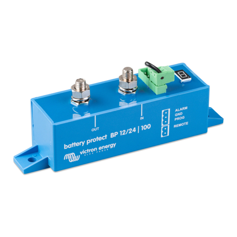
Victron energy Smart BatteryProtect 12/24V User manual

Smart BatteryProtect 12/24V
12/24V - 65A | 12/24V - 100A | 12/24V - 220A
rev 00 08/2022
ENGLISH

Table of Contents
1. Introduction ........................................................................................................................... 1
2. Features ................................................................................................................................ 2
3. Installation and wiring examples .................................................................................................. 3
3.1. Precautions and installation notes ......................................................................................... 3
3.2. Warning when connecting inverters and inverters/chargers ............................................................ 4
3.3. Wiring examples ............................................................................................................. 5
3.3.1. Smart BatteryProtect in a simple system ....................................................................... 5
3.3.2. Smart BatteryProtect remote on/off switch ..................................................................... 6
3.3.3. Smart BatteryProtect in a lithium battery system with external BMS ........................................ 6
3.3.4. Smart BatteryProtect in a lithium system with external BMS and load disconnect output ................ 7
3.3.5. Two Smart BatteryProtects for load and charger control ..................................................... 8
3.3.6. Smart BatteryProtect Alarm output wiring ...................................................................... 8
4. Operation and programming ....................................................................................................... 9
4.1. Operation modes ............................................................................................................ 9
4.2. Programming ............................................................................................................... 10
4.2.1. Programming via VictronConnect app ........................................................................ 10
4.2.2. Programming via PROG pin to GND pin method ............................................................ 10
4.2.3. Programming table .............................................................................................. 11
4.3. Status indicator ............................................................................................................ 11
4.4. Remote control and short circuit behavior .............................................................................. 12
4.5. Error & Warning modes ................................................................................................... 12
5. Compliance Statement ............................................................................................................ 13
6. Technical specifications .......................................................................................................... 14
6.1. Technical specifications ................................................................................................... 14
7. Appendix ............................................................................................................................. 15
7.1. Error and Warning codes ................................................................................................. 15
Smart BatteryProtect 12/24V

1. Introduction
The Smart BatteryProtect disconnects the battery from non-essential loads before it is completely discharged (which would
damage the battery) or before it has insufficient power left to crank the engine.
It also provides an alternative to disable chargers without a remote on/off port to protect from over-voltage.
Compared to the BatteryProtect, the Smart BatteryProtect can be conveniently programmed via Bluetooth and our
VictronConnect app or the PROG pin to GND pin method. All necessary parameters can be set in this way.
The Smart BatteryProtect is a uni-directional device. It can only deal with current in one direction, so either current to a load, or
current from a charger, but not both currents at the same time. In addition to this, current can only flow from the IN terminal to the
OUT terminal.
Smart BatteryProtect 12/24V
Page 1 Introduction

2. Features
The Smart BatteryProtect offers a wide range of different features. These include:
• Protection of the battery against excessive discharge and can be used as a system on/off switch.
• 12/24V auto ranging. The Smart BatteryProtect automatically detects system voltage one time only (can be re-triggered - see
section Programming table [11]).
• Easy Bluetooth programming.
• A special setting for Lithium batteries. This feature allows external control from a BMS like the VE.Bus BMS or Lynx Smart
BMS. If the load disconnect output of a BMS is connected to the Remote H input and the signal becomes free-floating, the load
is immediately disconnected.
• Ultra-low current consumption of 1.4mA with Bluetooth on: This is important in case of Li-ion batteries, especially after low cell
voltage shutdown.
• Over voltage protection: To prevent damage to sensitive loads due to over voltage. The load is disconnected whenever the DC
voltage exceeds 16.3V (for a 12V system) respectively 32.6V (for a 24V system).
• Ignition proof: No relays but MOSFET switches, and therefore no sparks.
• Delayed alarm output: The alarm output is activated if the battery voltage drops below the preset disconnect level fore more
than 12 seconds. Starting the engine will therefore not activate the alarm.
• Delayed load disconnect and delayed reconnect. Responding quickly within this delay, for example by reducing the load or
starting a generator or charger to charge the batteries, can prevent loads from being switched off.
For a full description of all features, please see the datasheets.
Smart BatteryProtect 12/24V
Page 2 Features

3. Installation and wiring examples
3.1. Precautions and installation notes
There are a few basic things to keep in mind when installing a Smart BatteryProtect:
1. The Smart BatteryProtect must be installed in a well-ventilated area and preferably close (max 50 cm) to the battery (but, due
to possible corrosive gasses not above the battery!).
2. Choose the correct cable size and length to match the load. Voltage drop over a long or undersized cable between the
battery plus and the SBP may result in a short circuit alarm when starting-up the load, or unexpected shutdown. You
can also find more information on selecting the right cable size and its protection in our book Wiring Unlimited.
3. A properly sized fuse must be inserted according to local regulations in the cable between the battery and the SBP.
4. Pay attention to the correct orientation. The SBP is designed to allow current to flow from IN (battery) to OUT (load) terminals
only. Reverse currents from OUT to IN terminals are strictly forbidden and will damage the device. If you wish to use the SBP
as a disconnection for a charge source, you must orient the unit in the system so that the current is flowing in the intended
direction, IN to OUT.
5. The short circuit protection of the SBP will be activated if you try to directly connect loads with capacitors, for example
inverters or inverter/chargers, on their DC inputs. For that use case, please use the SBP to control the remote on/off control
on the inverter, instead of disconnecting the higher power DC line. See also the warning on the next page.
6. Use a 1,5mm2 wire (included) for the GND connection, which should be connected directly to the battery negative terminal (or
the chassis of a vehicle). No other equipment should be connected to this wire.
7. The pin assignment of the connectors are printed either on the front or on the side of the housing.
8. The SBP automatically detects the system voltage once only during initial power up. The selected voltage (12 or 24 V) is
stored, and further automatic detection is disabled. See "d" in the programming table for how to reset it when re-using the
SBP in a different installation or use Bluetooth.
9. Do not connect the load output until the SBP has been fully programmed.
10. A remote on/off switch can be connected between Remote H and Remote L. Alternatively, terminal H can be switched high (to
battery positive), or terminal L can be switched low (to battery negative).
11. A buzzer, LED or relay can be connected between the alarm output terminal and the battery positive. Maximum load on the
alarm output: 50mA (short circuit proof).
Smart BatteryProtect 12/24V
Page 3 Installation and wiring examples
Other manuals for Smart BatteryProtect 12/24V
1
This manual suits for next models
3
Table of contents
Other Victron energy Power Distribution Unit manuals

Victron energy
Victron energy BatteryProtect 48V 100A User manual

Victron energy
Victron energy miniBMS User manual

Victron energy
Victron energy Smart BatteryProtect 12/24V User manual

Victron energy
Victron energy VE.Net DC User manual

Victron energy
Victron energy Smart BMS CL 12/100 User manual

Victron energy
Victron energy MultiPlus-II 12/3000/120-32 User manual

Victron energy
Victron energy BatteryProtect User manual

Victron energy
Victron energy Battery Protect Series User manual