bonitron M3539-S600Ax3-1500VDC User manual

4118355
M3539-S600Ax3-1500VDC
1500VDC Crowbar Module
Overvoltage Protector
Customer Reference Manual

Bonitron, Inc.
ii
Bonitron, Inc.
Nashville, TN
An industry leader in providing solutions for AC drives.
ABOUT BONITRON
Bonitron designs and manufactures quality industrial electronics that improve the reliability of
processes and variable frequency drives worldwide. With products in numerous industries, and
an educated and experienced team of engineers, Bonitron has seen thousands of products
engineered since 1962 and welcomes custom applications.
With engineering, production, and testing all in the same facility, Bonitron is able to ensure its
products are of the utmost quality and ready to be applied to your application.
The Bonitron engineering team has the background and expertise necessary to design,
develop, and manufacture the quality industrial electronic systems demanded in today’s market.
A strong academic background supported by continuing education is complemented by many
years of hands-on field experience. A clear advantage Bonitron has over many competitors is
combined on-site engineering labs and manufacturing facilities, which allows the engineering
team to have immediate access to testing and manufacturing. This not only saves time during
prototype development, but also is essential to providing only the highest quality products.
The sales and marketing teams work closely with engineering to provide up-to-date information
and provide remarkable customer support to make sure you receive the best solution for your
application. Thanks to this combination of quality products and superior customer support,
Bonitron has products installed in critical applications worldwide.

Bonitron, Inc.
iii
AC DRIVE OPTIONS
In 1975, Bonitron began working with AC inverter drive specialists at synthetic fiber plants to
develop speed control systems that could be interfaced with their plant process computers.
Ever since, Bonitron has developed AC drive options that solve application issues associated
with modern AC variable frequency drives and aid in reducing drive faults. Below is a sampling
of Bonitron’s current product offering.
WORLD CLASS PRODUCTS
Undervoltage Solutions
Power Quality Solutions
Uninterruptible Power for Drives
(DC Bus Ride-Thru)
Voltage Regulators
Chargers and Dischargers
Energy Storage
12 and 18 Pulse Kits
Filtering
Noise and Transient Suppression
Power Factor Correction
Overvoltage Solutions
Common Bus Solutions
Braking Transistors
Braking Resistors
Transistor/Resistor Combo
Line Regeneration
Dynamic Braking for Servo Drives
Single Phase Power Supplies
3-Phase Power Supplies
Common Bus Sharing Diodes
Isolation Diodes
Bus Filter Capacitance
Green/Sustainable Solutions
Portable Maintenance Solutions
Voltage Boosters
(for Solar and Wind Applications)
Line Regeneration
Power Factor Correction
Capacitor Formers
Battery Testers
Capacitor Testers
Capacitor Dischargers

M3539-S600Ax3-1500VDC
iv
This page intentionally left blank

Table of Contents
v
1. INTRODUCTION..........................................................................................................................1
1.1. Who Should Use...........................................................................................................................1
1.2. Purpose and Scope........................................................................................................................1
1.3. Manual Version and Change Record............................................................................................1
Figure 1-1: M3539-S600Ax3-1500VDC .................................................................................................1
1.4. Symbol Conventions Used in this Manual and on Equipment.....................................................2
2. PRODUCT DESCRIPTION............................................................................................................3
2.1. Part Number Breakdown ..............................................................................................................3
Figure 2-1: Example of Part Number Breakdown....................................................................................3
2-1: Current Rating per SCR....................................................................................................................3
2.2. General Specifications..................................................................................................................4
Table 2-2: General Specifications Table..................................................................................................4
2.3. General Precautions and Safety Warnings ...................................................................................5
3. INSTALLATION INSTRUCTIONS..................................................................................................7
3.1. Environment .................................................................................................................................7
3.2. Unpacking..................................................................................................................................... 7
3.3. Mounting ......................................................................................................................................7
Table 3-1: Chassis and Mounting Dimensions for the M3539 Module ...................................................7
3.4. Wiring and Customer Connections...............................................................................................8
3.4.1. Power Wiring....................................................................................................................................8
Table 3-2: Power Connection Specifications ...........................................................................................8
3.4.2. I/O Wiring.........................................................................................................................................8
Table 3-3: I/O Wiring Specifications.......................................................................................................8
3.5. Typical Configuration...................................................................................................................9
Figure 3-1: A006593-01 Overvoltage Protector Field Wiring Diagram ..................................................9
4. OPERATION..............................................................................................................................11
4.1. Functional Description ...............................................................................................................11
4.1.1. Jumper Selection.............................................................................................................................11
4.1.2. I/O Inputs and Outputs....................................................................................................................11
4.1.3. Internal Power Indicator..................................................................................................................12
4.2. Operation....................................................................................................................................13
Figure 4-1: Firing Response...................................................................................................................13
5. MAINTENANCE AND TROUBLESHOOTING...............................................................................15
5.1. Periodic Testing..........................................................................................................................15
5.2. Maintenance Items......................................................................................................................15
5.3. Troubleshooting..........................................................................................................................15
5.3.1. Signal indicator is not on ................................................................................................................15
5.3.2. Overtemperature .............................................................................................................................15
5.4. Technical Help –Before you call...............................................................................................15
6. ENGINEERING DATA................................................................................................................17
6.1. Ratings Charts.............................................................................................................................17
Table 6-1: Ratings Chart ........................................................................................................................17
6.2. Losses.........................................................................................................................................17
Table 6-2: Watt and Energy Losses .......................................................................................................17
6.1. Dimensions and Outlines............................................................................................................17
Figure 6-1: Chassis and Mounting Dimensional Outline .......................................................................17
7. APPLICATION NOTES...............................................................................................................19

M3539-S600Ax3-1500VDC
vi
This page intentionally left blank

User’s Manual
1
1. INTRODUCTION
1.1. WHO SHOULD USE
This manual is intended for use by anyone who is responsible for integrating,
installing, maintaining, troubleshooting, or using this equipment.
Please keep this manual for future reference.
1.2. PURPOSE AND SCOPE
This manual is a user’s guide for the Model M3539-S600Ax3-1500VDC Overvoltage
Protector. It will provide you with the necessary information to successfully install
and use this module in your application.
In the event of any conflict between this document and any publication and/or
documentation related to the application, the latter shall have precedence.
1.3. MANUAL VERSION AND CHANGE RECORD
Rev 01a adds the option jumpers TB7 for response time, remote firing option on
TB8, and a full form C contact on connector U3.
The Wiring Diagram was updated in Rev 01b.
The part number changed in Rev 01c.
Figure 1-1: M3539-S600Ax3-1500VDC
M3539-S600Ax3-1500VDC
2
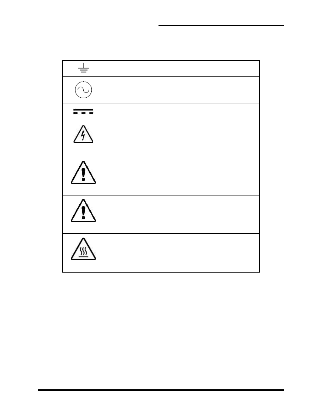
1.4. SYMBOL CONVENTIONS USED IN THIS MANUAL AND ON
EQUIPMENT
Earth Ground or Protective Earth
AC Voltage
DC Voltage
DANGER!
Electrical Hazard - Identifies a statement that indicates a shock
or electrocution hazard that must be avoided.
DANGER!
DANGER: Identifies information about practices or
circumstances that can lead to personal injury or death,
property damage, or economic loss.
CAUTION!
CAUTION: Identifies information about practices or
circumstances that can lead to property damage, or economic
loss. Attentions help you identify a potential hazard, avoid a
hazard, and recognize the consequences.
CAUTION!
Heat or burn hazard - Identifies a statement regarding heat
production or a burn hazard that should be avoided.

User’s Manual
3
2. PRODUCT DESCRIPTION
DC bus can experience dangerously high voltages. The M3539-S600Ax3-1500VDC
Overvoltage Protector (4118355) is designed to save all devices connected to the DC
bus by firing three SCRs when the voltage reaches a predetermined point, thus shunting
the potentially damaging energy.
2.1. PART NUMBER BREAKDOWN
Figure 2-1: Example of Part Number Breakdown
BASE MODEL NUMBER
The Base Model Number for all Overvoltage Protectors is M3539.
PROTECTION TYPE
One letter represents the selected Protection Type.
S –Uni-directional protection
D –Bi-directional protection
CURRENT RATING
Current Rating is indicated by a 3 digit number.
2-1: Current Rating per SCR
RATING CODE
CURRENT
300
300A
600
600A
NUMBER OF SCRS
Enter an “x” followed by the number of SCRs requested. Single SCR units have no
“x”.
VOLTAGE RATING
A 4-digit code represents the voltage trip point.
M3539
VDC
Ax
S
Ax
600
1500
3
BASE MODEL
PROTECTION TYPE
CURRENT RATING
NUMBER OF SCRS
VOLTAGE RATING

M3539-S600Ax3-1500VDC
4
2.2. GENERAL SPECIFICATIONS
Table 2-2: General Specifications Table
PARAMETER
SPECIFICATION
Input Voltage
24 VDC
System load bank
3x 2.7 ohm, Wye connected
System Voltage
900VDC Nominal
Peak Current
1800ADC
Trip Point
Jumper adjustable, 1200V, 1300V, 1400V, 1500V
Discharge Time
6 seconds
10 minute off time
Reaction Time
100 µS
Operating Temp
-40C to +70C
Discharge Waveform
Exponential
Cooling
Convection, no forced air
Storage Temp
-40C to +70 C
Operating Temperature Range:
-40C to +70 C
Humidity
95% non-condensing
Altitude
10,000 ft
Control I/O
Input: 24VDC, 120mA max
Outputs: 125VAC, 120mA,
Over-temp
Crowbar Fired Signal
Indicators
Power

User’s Manual
5
2.3. GENERAL PRECAUTIONS AND SAFETY WARNINGS
DANGER!
HIGH VOLTAGES MAY BE PRESENT!
NEVER ATTEMPT TO OPERATE OR SERVICE THIS EQUIPMENT
WITH ACCESS DOORS OR COVERS OPENED!
FAILURE TO HEED THESE WARNINGS MAY RESULT IN
SERIOUS BODILY INJURY OR DEATH!
CAUTION!
HIGH TEMPERATURES MAY BE GENERATED BY THIS
EQUIPMENT DURING NORMAL OPERATION!
THIS EQUIPMENT SHOULD BE INSTALLED ON A NON-
FLAMMABLE SURFACE IN A WELL VENTILATED AREA WITH A
MINIMUM OF 2INCHES OF CLEARANCE ALL AROUND.
LETHAL VOLTAGES CAN EXIST IN UNIT AFTER POWER HAS
BEEN REMOVED.ALLOW 5MINUTES FOR CAPACITOR BANKS
TO DISCHARGE,AND INSURE THERE IS LESS THAN 40VDC
ON THE DC BUS BEFORE ATTEMPTING SERVICE.
ALWAYS ALLOW TIME FOR THE UNIT TO COOL BEFORE
ATTEMPTING SERVICE ON THIS PRODUCT!
INSTALLATION AND/OR REMOVAL OF THIS PRODUCT SHOULD
ONLY BE ACCOMPLISHED BY A QUALIFIED ELECTRICIAN IN
ACCORDANCE WITH NATIONAL ELECTRICAL CODE OR
EQUIVALENT REGULATIONS.
ANY QUESTIONS AS TO APPLICATION, INSTALLATION, OR SERVICE
SAFETY SHOULD BE DIRECTED TO THE EQUIPMENT SUPPLIER.

M3539-S600Ax3-1500VDC
6
This page intentionally left blank
User’s Manual
7
3. INSTALLATION INSTRUCTIONS
WARNING!
Installation and/or removal of this product should only be performed by a
qualified electrician in accordance with National Electrical Code or local
codes and regulations.
Proper installation of the Power Supply Modules should be accomplished following the
steps outlined below. Be sure to refer to the AC Drive instruction manual as these steps
are performed. Please direct all installation inquiries that may arise during the
installation and start up of this product to the equipment supplier or system integrator.
3.1. ENVIRONMENT
The module should be installed in an area protected from moisture and falling debris.
Buildup of dust or debris may cause poor performance and possibly a failure.
Operating in a wet environment can pose a shock hazard. The recommended
temperature range for operating or storing this module is -40C to +70C.
3.2. UNPACKING
Upon receipt of this product, please verify that the product received matches the
product that was ordered and that there is no obvious physical damage to the unit. If
the wrong product was received or the product is damaged in any way, please
contact the supplier from which the product was purchased.
3.3. MOUNTING
The installation site for the module should be chosen with several considerations in
mind:
The unit requires a minimum clearance of two (2) inches in all directions around it
when mounted near a non-heat source.
Unit should not be exposed to falling debris or condensation.
See Figure 6-1 for the Chassis and Mounting Dimensional Outline.
Table 3-1: Chassis and Mounting Dimensions for the M3539 Module
MODEL NUMBER
OVERALL
(IN INCHES)
MOUNTING
(IN INCHES)
WEIGHT
(LBS.)
HEIGHT
WIDTH
DEPTH
HEIGHT
WIDTH
M3539-S 600Ax3-1500VDC
13
12.3
7.6
10
11.57
30

M3539-S600Ax3-1500VDC
8
3.4. WIRING AND CUSTOMER CONNECTIONS
3.4.1. POWER WIRING
DANGER!
This unit contains substantial capacitance and can
maintain lethal voltages for a long time after power is
removed! Insure that the DC bus level has dropped below
40VDC before attempting to work on or with this unit!
WARNING!
Only qualified electricians should perform and maintain the
interconnection wiring of this product. All wiring should be
done in accordance with local codes.
Table 3-2: Power Connection Specifications
UNIT
TERMINAL
CONNECTION
TORQUE
M3539-S600Ax3 1500VDC
RL1, RL2, RL3,
DC1-, DC2-, DC3-
½” stud
300 in-lbs
3.4.2. I/O WIRING
Table 3-3: I/O Wiring Specifications
TERMINAL
FUNCTION
ELECTRICAL
SPECIFICATIONS
MIN WIRE
AWG
MAX WIRE
AWG
DESCRIPTION
SECTION
TB1-1
TB1-2
DC+ Sense Line
1500V, 1mA
28
12
4.1.2.1
TB2
Voltage Trip
Point Selection
Jumper
300V, 1mA
28
12
4.1.1.1
TB3-1
SCR Fire Signal
24V, 100mA
28
12
4.1.2.2
TB3-2
SCR Fire Signal
24V, 100mA
28
12
4.1.2.2
TB3-3
TB3-4
TB3-5
SCR Fired
Signal
300VAC, 120mA max
28
12
4.1.2.3
TB3-6
TB3-7
Normally closed
Over temp
125VAC, 15 Amps
28
12
4.1.2.4
TB7-1
TB7-2
Response Time
Selection
Jumper
300V, 1mA
28
12
4.1.1.2
TB8-1
TB8-2
TB8-3
Crowbar Fire
Signal Operation
Jumper
300V, 1mA
28
12
4.1.1.3
User’s Manual
9
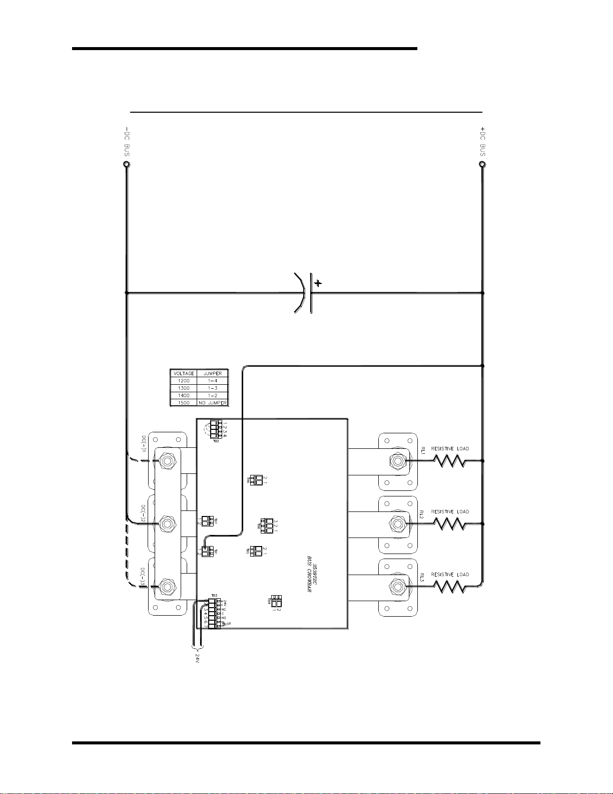
3.5. TYPICAL CONFIGURATION
Figure 3-1: A006593-01 Overvoltage Protector Field Wiring Diagram
Dwg #: 100287 Rev: 20120717

M3539-S600Ax3-1500VDC
10
This page intentionally left blank

User’s Manual
11
4. OPERATION
4.1. FUNCTIONAL DESCRIPTION
The M3539-S600Ax3-1500VDC Overvoltage Protector (4118355) is
connected to the DC bus. When the voltage goes above a certain
threshold, the SCRs will fire, limiting the voltage from going higher. The
energy is dissipated through the field resistance. This is designed with
heatsinks to handle time constants up to 12 seconds without fan or
other air circulation. Once the current drops below the SCR latching
threshold, the circuit turns off resets for another high voltage spike.
Unit has three parallel SCRs, each capable of carrying 600A peak. This
will allow for parallel load resistor connections.
WARNING!
Each connection must have a separate resistor element! If the
resistor connections are all connected at the crowbar module, the
SCRs will not share current, and may misfire!
This can cause overheating and catastrophic failure!
4.1.1. JUMPER SELECTION
4.1.1.1. TB2-OVERVOLTAGE SETPOINT SELECTION JUMPERS
A jumper is used to determine the overvoltage setpoint. This is the
point at which the SCRs will fire regardless of other conditions. The
voltage is sensed between TB1 and the DC- power connection.
Jumper adjustment:
For 1200V: connect TB2-1 to TB2-4
For 1300V: connect TB2-1 to TB2-3
For 1400V: connect TB2-1 to TB2-2
For 1500V: no jumper
4.1.1.2. TB7 -RESPONSE TIME SELECTION JUMPER
This jumper determines the response time of the circuit. If the jumper is
installed, the unit will fire when the voltage sensed on TB1 is above the
setpoint within 2ms.
If the jumper is not installed, the unit will fire within 20ms.
4.1.1.3. TB8 -CROWBAR FIRE SIGNAL OPERATION JUMPER
This jumper determines the firing operation of the external override
signal. See Section 4.1.2.2 for details on the settings.
4.1.2. I/O INPUTS AND OUTPUTS
4.1.2.1. TB1-1&2 HIGH VOLTAGE SIGNAL +
The unit will sense the DC BUS positive voltage from TB1-1 or TB1-2.
The differential voltage between this terminal and the DC- terminals will
determine when the SCR crowbar fires.
These terminals are an electrical node, and are connected on the
board. Do not hook the DC- reference to these terminals as it will be a
direct short.

M3539-S600Ax3-1500VDC
12
The voltage attached to this terminal is referenced to the DC1-, DC2-,
and DC3- main power terminals.
4.1.2.2. TB3-1&2 CROWBAR FIRE SIGNAL
This signal can be used to remotely fire the SCRs with a 24VDC signal.
Terminal 1 is the +24V signal, terminal 2 is the 24V- or common signal.
The firing operation will be determined by the jumper on TB8.
If the jumper on TB8 is installed in terminals 2 and 3, the unit will fire
when there is a 24VDC falling edge on TB3-1&2.
If the jumper is on TB8 terminals 1 and 2, the SCR fire signal has no
effect.
In either case, the unit will fire when the High Voltage sensing voltage
between TB1 and DC- reaches the level set by the jumpers on TB2.
4.1.2.3. TB3-3&4&5 SCR FIRED SIGNAL
The SCR Fired signal will change when the SCRs are triggered. These
outputs are isolated so they may be interfaced with PLC or external
switch.
Terminal 3 is a normally closed signal.
Terminal 4 is common to both signals.
Terminal 5 is a normally open signal.
4.1.2.4. TB3-6&7 OVER TEMPERATURE SIGNAL
The over temperature contact opens when the heatsink temperature
reaches 220±5°F and closes when it reaches 190±10°F.
4.1.3. INTERNAL POWER INDICATOR
The unit has an indicator in the control board that will be illuminated when
external 24V is applied.

User’s Manual
13
4.2. OPERATION
The crowbar is designed to allow for remote firing and indication. The DC bus is
monitored constantly, and the SCRs will fire under the following conditions:
1. If it goes above the overvoltage setpoint, the SCRs will fire regardless of the
state of the 24V input supply.
2. If the DC bus is at a level below the overvoltage trip point, a negative edge, or
removal of power from the 24V input will cause the SCRs to fire. This may be
useful to drain the bus for maintenance after the main input power supply has
been removed or disabled. This function can be disabled by removing the
jumpers from TB8-2&3
Please see the timing chart below for a graphical representation of the firing
responses.
Figure 4-1: Firing Response
DC Bus
SCR Fire
Signal
(input)
SCR
Fired
Signal
(output)
Time
0 Volts
Normal
Trip Point
~200 Volts

M3539-S600Ax3-1500VDC
14
This page intentionally left blank
Table of contents
Other bonitron Power Distribution Unit manuals

Popular Power Distribution Unit manuals by other brands

Ediseja 21
Ediseja 21 LSU 110/32 user manual

Eaton
Eaton FlexPDU user manual

ITT
ITT POWERLOCK BOX Translation of the original operating instructions

Belkin
Belkin PureAV PF30 user manual

Ilsco
Ilsco SpecPRO CRM 26 Series quick start guide

Scame electrical solutions
Scame electrical solutions ADVANCE-GRP Series Installation, use and maintenance

Dawnco
Dawnco STARLOOK- D manual

Siemens
Siemens XJ-L Busway System Storage, Installation and Maintenance Instructions

CyberPower
CyberPower 649532893522 Specification sheet

S&C
S&C VacuFuse Installation and operation

Middle Atlantic Products
Middle Atlantic Products RackLink RLNK-915R quick start guide

nVent Hoffman
nVent Hoffman DPC user manual


