ferroamp Power Distribution 5 User manual

Installation manual
Swe & En
Power
Distribution 5
Rev A01
Rev B01


1
Innehållsförteckning / Table of contents
SVENSKA........................................................................................................................................................................................................................................ 2
1Introduktion........................................................................................................................................................................................................................ 2
1.1 Ingående artiklar ...................................................................................................................................................................... 2
1.2 Varningar och förbehåll........................................................................................................................................................... 2
1.3 Förklaringar av säkerhetsaviseringar.................................................................................................................................... 2
1.4 Dimensioner .............................................................................................................................................................................. 2
1.5 Komponenter ............................................................................................................................................................................ 2
1.6 Anslutningar.............................................................................................................................................................................. 3
1.7 Genomföringar.......................................................................................................................................................................... 3
2Installation.......................................................................................................................................................................................................................... 3
2.1 Nödvändiga verktyg ................................................................................................................................................................. 3
2.2 Orientering av genomföringar................................................................................................................................................ 3
2.3Montering på vägg ................................................................................................................................................................... 3
2.4 Anslutning av SSO:er (1-5) ..................................................................................................................................................... 4
2.5 Anslutning till likspänningsnät.............................................................................................................................................. 4
3Underhåll............................................................................................................................................................................................................................. 5
ENGLISH ......................................................................................................................................................................................................................................... 6
1Introduction........................................................................................................................................................................................................................ 6
1.1 Included items .......................................................................................................................................................................... 6
1.2 Warnings and recommendations ........................................................................................................................................... 6
1.3Explanation of safety notices ................................................................................................................................................. 6
1.4 Dimensions................................................................................................................................................................................ 6
1.5 Components .............................................................................................................................................................................. 6
1.6 Connections............................................................................................................................................................................... 7
1.7 Inlets and cable glands............................................................................................................................................................ 7
2Installation.......................................................................................................................................................................................................................... 7
2.1 Required tools........................................................................................................................................................................... 7
2.2 Feedthrough orientation......................................................................................................................................................... 7
2.3 Placement on wall.................................................................................................................................................................... 7
2.4 Installation of SSO:s (1-5)....................................................................................................................................................... 8
2.5 DC nanogrid connection .......................................................................................................................................................... 8
3Maintenance....................................................................................................................................................................................................................... 9
Revision history
Date
Revision
2021.01.14
A01–Swedish and English version
PN: PD01326, Rev: A01, Copyright Ferroamp Elektronik AB 2021. Document subject to change without prior notice.
Verify that you have the latest version of this manual on our website. www.ferroamp.com/downloads

2
SVENSKA
1Introduktion
I detta häfte finner du anvisningar för installation av din Power
Distribution 5. Se till att läsa instruktionen noggrant för att undvika
onödiga fel.
1.1 Ingående artiklar
Följande artiklar ingår vid leverans av en Power Distribution 5:
Artikel
Antal
Kopplingslåda
1
Brytare
1
Säkringar (15A, 1000V, gPV)
10
Säkringshållare
10
Kabelgenomföringar
8
Täcklock (Genomföringar)
8
Nyckel
1
Varningsklistermärke (Swe/ En)
1/1
1.2 Varningar och förbehåll
UPPMANING! Läs igenom hela installationsmanualen innan du
påbörjar arbetet.
UPPMANING! Använd endast denna produkt enligt angivna
instruktioner för att undvika eventuella faror.
VARNING! Den elektriska installationen skall utföras av behörig
installatör och i enlighet med gällande elektrisk standard och
säkerhetsföreskrifter.
VARNING! Du får ej ansluta enheter till likspänningsnätet när det
är spänningssatt.
VARNING! Risk för elektrisk stöt och ljusbåge om produkten inte
hanteras i enlighet med manualens instruktioner.
VARNING! Använd inte produkten om du misstänker skada eller
lösa föremål inuti produkten. Låt den inspekteras av kvalificerad
personal före användning.
VARNING! Använd inte produkten om hela eller del av kapslingen
är borta, till exempel vid reparation, rör inte utsatta delar.
NOTERA!Garantin gäller ej om produkten modifierats eller inte
installeras i enlighet med denna manual.
1.3 Förklaringar av säkerhetsaviseringar
1.4 Dimensioner
Alla mått är i millimeter om inte annat anges.
1.5 Komponenter
1. Kabelgenomföring
2. DC Brytare
3. Säkringar & Säkringshållare
Blixtsymbolen i en liksidig triangel varnar för farlig
elektrisk spänning.
Utropstecknet i en liksidig triangel är avsedd att
varna användaren om att vårdslöshet av denna
information kan vara livshotande!
Utropstecknet i en cirkel är avsett att informera
användaren om att försummelse av denna
information kan vara förknippad med kroppsskada
och / eller skada på produkten.

3
1.6 Anslutningar
Anslutningar för SSO:er:
1. 5 x PE (max 6 mm²)
2. 5 x L- (1–10 mm²)
3. 5 x L+ (1–10 mm²)
Anslutningar för likspänningsnät:
4. 1 x PE (max 25 mm²)
5. 1 x L- (max 25 mm²)
6. 1 x L+ (max 25 mm²)
1.7 Genomföringar
Antal
Genomföring
Kabeldiameter (mm)
6
M20x1.5
6 - 12
1
M25x1.5
13 - 18
1
M32x1.5
13 - 20
2Installation
Installationsavsnittet kommer att ta dig genom hela processen steg
för steg för hur du ska installera en Power Distribution 5.
NOTERA!Ferroamp tar inte ansvar för skador som åsamkas
produkten på grund av felaktig eller vårdslös installation.
NOTERA! Ferroamp rekommenderar att ändhylsor används för
samtliga anslutningar med mångtrådiga ledare.
1
Gäller Power Distribution 5, PN: PS00778A03 (PN står på etiketten på insidan av
skåpsdörren)
2.1 Nödvändiga verktyg
•Skruvmejslar:
oSpår - 1x5 mm
oKryss –TBD
•Hylsnycklar:
oNo. 1 - 27 mm
oNo. 2 - 32 mm
oNo. 3 - 39 mm
•Kabelskalare och kabelsax (1 - 120 mm²)
•Momentnyckel
2.2 Orientering av genomföringar
NOTERA! Power Distribution 5 är för-konfigurerat att dra in kablar
genom skåpets botten
1
. Om du istället vill ha
kabelgenomföringarna uppåt behöver du:
1. Vända på DIN-skenan som håller säkringar och brytare. Lossas
enkelt med två skruvar i vardera ända.
2. Vända täckplåten så att texten hamnar rätt.
2.3 Montering på vägg
1. Montera skruvar & brickor i monteringsöglorna mot väggen
(fästelement för väggen ingår inte i installationskittet).
•Arbeta inte ensam. I en nödsituation kan en
annans närvaro vara nödvändig!
•Elinstallationen måste uppfylla nationella /
lokala lagar och förordningar, lämpliga
standarder och tillämpliga krav från erkända
organisationer.
•Den elektriska installationen skall utföras av
behörig installatör och i enlighet med
gällande elektrisk standard och
säkerhetsföreskrifter
•Se till att placeringen av Power Distribution 5
aldrig utgör ett hinder för nödutrymning, i
enlighet med nationell och lokal lagstiftning.

4
2.4 Anslutning av SSO:er (1-5)
NOTERA!För att beräkna korrekt kabeldimension, använd
Ferroamps kabelkalkylator som finns tillgänglig på
www.ferroamp.se under supportfliken.
1. Skruva loss täckplåten enligt bilden ovan. Täckplåten är
kopplad med en jordkabel till skåpet.
2. Anslut L- , L+ & PE från SSO till respektive skruvterminal.
3. Se till att samtliga terminaler är åtdragna till 2.5 Nm med
momentnyckel.
2.5 Anslutning till likspänningsnät
1. Anslut likspännings kabeln (L+, L- & PE) till de markerade
terminalerna.
2. Se till att samtliga terminaler är åtdragna till 2.5 Nm med
momentnyckel.
3. Montera tillbaka frontplåten.
4. Fäst varningsdekalen på kopplingsskåpets front.
•Se till att likspänningsnätet är inkopplat på
rätt terminaler.
•Kontrollera att alla terminaler och
jordanslutningar i skåpet är åtdragna med 2.5
Nm (finns risk att vibrationer orsakade av
transport lösgör anslutningarna).

5
3Underhåll
Vid byte av utlöst säkring skall en säkring med följande
specifikation användas:
Driftklass: gPV
Dimensioner: 10x38 mm
Max ström: 15 A
Märkspänning: 1000 VDC
Brytförmåga: 20 kA

6
ENGLISH
1Introduction
In this booklet you will find installation instructions for your Power
Distribution 5. Please read the instructions carefully to ensure that
no unnecessary errors occur.
1.1 Included items
The following articles are included upon delivery of a Power
Distribution 5:
Article
Amount
Distribution enclosure
1
MCB
1
Fuses (15A, 1000V, gPV)
10
Fuse holder
10
Cable glands
8
Cable glands covers
8
Key
1
Warning sticker (En/Swe)
1/1
1.2 Warnings and recommendations
RECOMMENDATION! Read through the manual before installation.
RECOMMENDATION! Only use this product according to the
instructions supplied to avoid any danger.
WARNING! The electrical installations shall be conducted by
authorized personnel and in accordance with local and national
electrical standards and safety measures.
WARNING! You are not allowed to connect units to the DC nanogrid
when it is energized.
WARNING! Risk of electrical shock/arc if the product is not used
according to the instructions in the manual.
WARNING! Do not use the product if you suspect the product is
damaged. Let it be inspected by qualified personnel before use.
WARNING! Do not use the product if the housing has been
tampered with or not intact, for example during repair, do not
touch exposed parts.
NOTE! The warranty does not apply if the product has been
modified, tampered with, or not installed in accordance with this
manual.
1.3 Explanation of safety notices
1.4 Dimensions
All dimensions are in mm if nothing else is specified.
1.5 Components
1. Cable glands
2. DC Brakers
3. Fuses & Fuse holders
The flash symbol in an equilateral triangle warns
of dangerous voltage.
The exclamation mark in an equilateral triangle is
intended to warn the user that negligence of this
information can be life threatening!
The exclamation mark in a circle is intended to
inform the user that neglect of this information
may be associated with bodily injury and / or
damage to the product.

7
1.6 Connections
Connections for SSOs:
1. 5 x PE (max 6 mm²)
2. 5 x L- (1–10 mm²)
3. 5 x L+ (1–10 mm²)
Connections for DC nanogrid:
4. 1 x PE (max 25 mm²)
5. 1 x L- (max 25 mm²)
6. 1 x L+ (max 25 mm²)
1.7 Inlets and cable glands
Amount
Gable glands
Cable diameter (mm)
6
M20x1.5
6 - 12
1
M25x1.5
13 - 18
1
M32x1.5
13 - 20
2Installation
The installation section will take you step by step through the
process of installing a Power Distribution 5.
NOTE! Ferroamp does not take responsibility for damages on the
product caused by incorrect or careless installation.
NOTE! We recommend that you use end terminals for all
connection points that have multi-threaded conductors.
2
Applies for Power Distribution 5, PN: PS00778A03 (PN number is stated on label
placed on the inside of the cabinet door).
2.1 Required tools
•Screwdrivers:
oSlot drive 1x5 mm
oPhilips - TBD
•Socket wrench:
oNo. 1 - 27 mm
oNo. 2 - 32 mm
oNo. 3 - 39 mm
•Cable peeler and cutter (1 - 120 mm²)
•Torque wrench
2.2 Feedthrough orientation
NOTE! Power Distribution 5 is pre-configured for having cables
feed through the bottom of the cabinet
2
. If you wish to have the
cables feed through the top of the cabinet you need to:
1. Change direction of the DIN-rail that holds fuses and breaker.
Remove the two screws located at the ends of the DIN-rail.
2. Change direction of the front cover so that the text is
displayed correctly.
2.3 Placement on wall
1. Mount screws & washers in the brackets towards the wall.
(Screws elements are not included the installation kit)
•Do not work alone. In an emergency, someone
else's presence may be necessary!
•The electrical installation must comply with
national / local laws and regulations,
appropriate standards and applicable
requirements from recognized organizations.
•The electrical installation must be carried out
by a qualified installer and in accordance with
the applicable electrical standard.
•Ensure that the location of the Power
Distribution 5 never is an obstacle to an
emergency evacuation path. In accordance
with national and local laws.

8
2.4 Installation of SSO:s (1-5)
NOTE! To calculate correct cable dimensions you can use
Ferroamp’s online cable calculator, available at
www.ferroamp.com under the support section.
1. Unscrew the front plate as shown above. The front plate is
attached with a PE-cable to the cabinet.
2. Connect L-, L+ & PE from each SSO to designated screw
terminal.
3. Make sure that all terminals are tightened to 2.5 Nm, use a
torque wrench.
2.5 DC nanogrid connection
1. Connect the DC nanogrid cable (L+, L- & PE) to the marked
terminals.
2. Make sure that all terminals are tightened to 2.5 Nm, use a
torque wrench.
3. Place the front panel in position according to figure above.
4. Place the warning label on the front door.
•Make sure that the DC nanogrid is connected
to correct terminals.
•Check that all terminals and PE-connections
are tightened to 2.5 Nm (there is a risk that
the connections loosen during transportation
due to vibration).

9
3Maintenance
When a fuse trips replace it with a fuse with the following
specifications:
Characteristic: gPV
Dimensions: 10x38 mm
Current rating: 15 A
Voltage rating: 1000 VDC
Breaking capacity: 20 kA

Electricity.
Reinvented.
Table of contents
Languages:
Other ferroamp Power Distribution Unit manuals
ferroamp
ferroamp Power Distribution 15 User manual
ferroamp
ferroamp SSO User manual
ferroamp
ferroamp EnergyHub XL Single 21 kW User manual
ferroamp
ferroamp EnergyHub User manual

ferroamp
ferroamp ESS Power Case User manual

ferroamp
ferroamp EnergyHub XL User manual
ferroamp
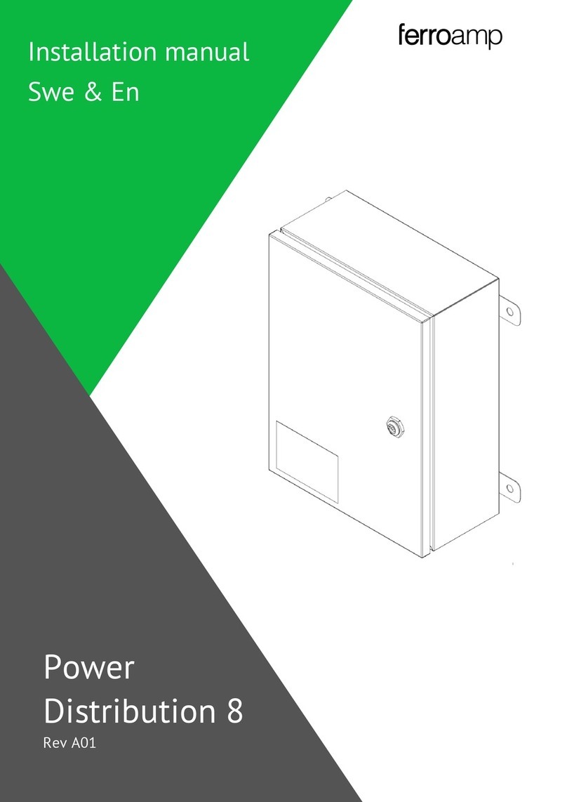
ferroamp Power Distribution 8 User manual
Popular Power Distribution Unit manuals by other brands

ABB
ABB RELION 650 SERIES Applications manual
Compaq
Compaq 207590-B21 - Power Distribution Unit Strip Quick install guide

EuroLite
EuroLite SAB-16XS user manual

LEGRAND
LEGRAND Mosaic 775 40 quick start guide

Ilsco
Ilsco SpecPRO CRM 26 Series quick start guide
Allen-Bradley
Allen-Bradley 140G2-K H Series manual


