BOOMLIGHTS LC-1X User manual
Page 1of 13
LC-1X
1-CH LIGHTING CONTROLLER
USER MANUAL
©BOOMLIGHTS
265 McNeilly Road
Stoney Creek, ON
L8E 5H2
Canada
© 2021 BOOMLIGHTS. All rights reserved.

Page 2of 13
CONTENTS
WARNING............................................................................................................................3
WHAT’S INCLUDED .........................................................................................................3
SAFETY INSTRUCTIONS......................................................................................................3
1.0 INTRODUCTION............................................................................................................ 3
1.1 Overview....................................................................................................................3
1.2 Features.....................................................................................................................4
2.0 OPERATION...................................................................................................................5
2.1 Default Set-Up...........................................................................................................5
2.2 Getting Started..........................................................................................................5
2.3 Colour Combinations ...............................................................................................6
2.4 DMX Output ..............................................................................................................6
2.4.1 DMX Address Table............................................................................................8
2.5 Changing the Default Settings.................................................................................8
2.5.1 Changing the MIDI Note DIP Switches .............................................................8
2.5.2 MIDI Note DIP Switch Table ..............................................................................9
2.5.3 Changing the MIDI Channel DIP Switches .....................................................11
2.5.4 MIDI Channel DIP Switch Table ......................................................................11
2.6 Linking Multiple Units Together............................................................................11
3.0 CURRENT LIMIT ..........................................................................................................13
4.0 TROUBLESHOOTING..................................................................................................13
5.0 SPECIFICATIONS .........................................................................................................13

Page 3of 13
WARNING
WHAT’S INCLUDED
•LC-1X
•DC12V 2A 90~240VAC Power Supply
•User Manual
•40” RGB LED Strip
•25’USB Type A to Type B Cable
SAFETY INSTRUCTIONS
•Do not operate this unit at temperatures above 113°F
•Only use the supplied power supply
•Make sure the power supply’s cord is not pinched or damaged in any way
•Make sure the power supply is plugged into an appropriate voltage source
•Before making any changes to the DIP switches, turn off the power by unplugging the unit
•If any defects with the unit are discovered, please contact an authorized service technician
for assistance
1.0 INTRODUCTION
1.1 Overview
The LC-1X is a single channel RGB LED and DMX lighting controller that has been specially designed
by musicians for musicians. Treat your lighting like an instrument by using MIDI to create custom
automated light shows. No additional hardware or software required. The LC-1X seamlessly
integrates with any existing hardware or software set-up. Just plug and play to begin elevating your
performances with synchronized lighting.
The LC-1X is controlled using 3 MIDI notes, which represent 1 RGB channel. An individual RGB colour
is designated to a specific MIDI note. MIDI velocity is used to control the brightness/intensity of RGB
colours. By combining MIDI notes within an RGB channel group and adjusting their velocities, you
can create an array of colours within the RGB colour spectrum.
For your own safety, please read this manual to learn how to safely
use, store and maintain the LC-1X prior to use.
CAUTION! Please keep this unit stored in an area with no moisture.
Page 4of 13
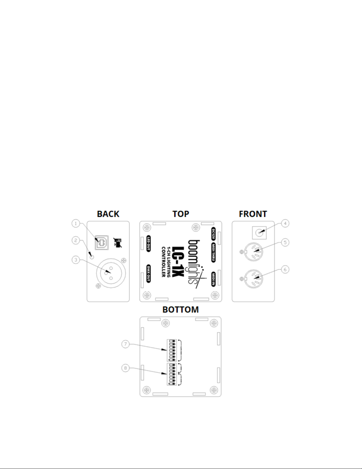
1.2 Features
1 - RGB Channel Output Connector: The 4-pin USB type B connector is used for driving any 12V
common anode RGB LED strip. DO NOT CONNECT TO A USB PORT ON A COMPUTER!
2 - Indicator Light: Displays the colour output of the unit. This is the colour that will ultimately be
displayed by any connected LED strip or DMX light. However, this light will display the colour output
regardless of whether an LED strip or DMX light is connected.
3 - DMX Out:Outputs DMX 512 data to any connected DMX lights.
4 - DC12V Input:Main power connection for the unit used to connect the DC12V power supply.
5 - MIDI Thru: Passes through an exact copy of the MIDI input signal. This allows multiple units or
other MIDI devices to be chained together and controlled by a common source.
6 - MIDI In: Transfers MIDI input signal from a connected source to the unit.
7 –MIDI Note DIP Switch: DIP switch used to set which MIDI notes the unit will respond to.
8 –MIDI Channel / DMX DIP Switch: DIP switch used to set which MIDI channel the unit will
respond to and which DMX addresses the unit outputs to.

Page 5of 13
2.0 OPERATION
2.1 Default Set-Up
The unit comes set up with the following default settings: MIDI notes 0, 1 and 2 (C-2, C#-2 and D-2),
control the colours green, red and blue respectively. The unit’s default MIDI channel is set to be MIDI
channel 1. Both the MIDI channel and MIDI note settings can be changed easily by adjusting the DIP
switches on the bottom of the unit.
Below is a diagram that illustrates a typical set-up. You can control an LED strip and/or DMX lights. It
is important to note that all of the LED strips and DMX lights connected to the unit will display the
same colour. You cannot individually control LED strips and DMX lights and set them to different
colours. All of the lights respond to the MIDI notes and MIDI channel set by the DIP switches on the
bottom of the unit. The channel indicator light on the front of the unit previews the colour that the
unit will output to any connected LED strips and/or DMX lights. This light will illuminate even if there
are no LED strips or DMX lights connected to the unit. This useful feature can be used to program a
light show without having to connect any LED strips and/or DMX lights.
2.2 Getting Started
Before plugging in the power supply, which will power the unit on, plug in an LED strip and/or DMX
light(s) into the unit. LED strips should be plugged into the “LED Out”connector, while DMX lights
should be plugged into the “DMX Out” connector. You can daisy-chain multiple DMX lights by
connecting a DMX cable from the “DMX Out”of the DMX light that is directly connected to the LC-1X
to the “DMX In”of another DMX light. You can repeat this sequence to daisy-chain up to a total of 16
DMX lights. See section 2.4 for more information about how the LC-1X transmits DMX signals.
Next connect the “MIDI Out” of your MIDI device to the “MIDI In”of the LC-1X via a MIDI cable.
Ensure you are using the correct MIDI channel and MIDI notes on your MIDI device. See section 2.3.1
for more information about how to configure the MIDI channel and MIDI notes that the LC-1X will
respond to.
Power on the LC-1X by plugging in the provided DC12V power supply to the “DC12V” jack on the unit.
The unit will briefly cycle through the colours white, green, red and blue, which be displayed by the

Page 6of 13
unit’s indicator light. You should see all of the colours from the start-up cycle illuminate on any
connected LED strip and/or DMX light, otherwise there is an issue that requires troubleshooting.
2.3 Colour Combinations
You can create an array of different colours within the RGB colour spectrum by illuminating various
combinations of green, red and blue. For example, if the green and red LEDs are simultaneously
illuminated, the resultant colour will be yellow. MIDI velocity can be adjusted to change the overall
brightness/intensity of the colour designated to the corresponding MIDI note. MIDI velocity changes
can also be used to create additional colours and shades, particularly when the MIDI velocity value
of multiple notes are unequal.
The following table shows the available fundamental colours and their corresponding RGB colour
combinations.
COLOUR
RGB FORMULA
RED
R
GREEN
G
BLUE
B
YELLOW
R + G
MAGENTA
R + B
CYAN
G + B
WHITE
R + G + B
2.4 DMX Output
While conventional DMX consoles and software allow for individual control of daisy-chained DMX
lights, configuring a DMX set-up and programming light shows via DMX is notoriously complicated
and frustrating. To streamline and simplify this process, the LC-1X controls all daisy-chained DMX
lights with the same signal output. For example, if you have several of the same DMX PAR lights
daisy-chained together and you trigger the first light in the chain to illuminate red, all additional
lights in the chain will receive the exact same signal and illuminate red as well. A single DMX signal
chain is referred to as a “universe”.
A single DMX universe can output 512 channels in which each channel can be set to a value between
0 and 255. Most DMX lights take up anywhere between 10 and 20 channels. You can find the specific
channel designations for a particular DMX light within its user manual.
Each channel on any given RGB DMX light controls various parameters such as colour, strobe speed
and brightness. To adhere to the same conventions as Boomlights’ RGB LED MIDI control protocol,
the only DMX channels the LC-1X will utilize will be the colours red, green and blue as well as the
overall brightness. This allows for each colour of an RGB DMX light to be designated to and
controlled by the corresponding MIDI note within a 3 MIDI note group.
Setting the address of a DMX light effectively sets the first address of the DMX universe signal it will
respond to. For example, if you are using a 10 channel DMX light and set its address to “20”, that
Page 7of 13
light will respond to DMX channels 20 through 29. It is also important to note that you can have
multiple DMX lights within that universe set to the same channel.
While DMX lights have a variety of different channel configurations, the LC-1X is designed to
accommodate a variety of standard configurations of DMX lights. As shown on the table in section
2.4.1, a number of DMX lights will require the base address to be set to channel 20 due to the fact
that the LC-1X is designed to transmit DMX data to that specific address. However, the LC-1X is
configured to transmit DMX data at additional addresses, which allows it to control a variety of
different DMX lights.
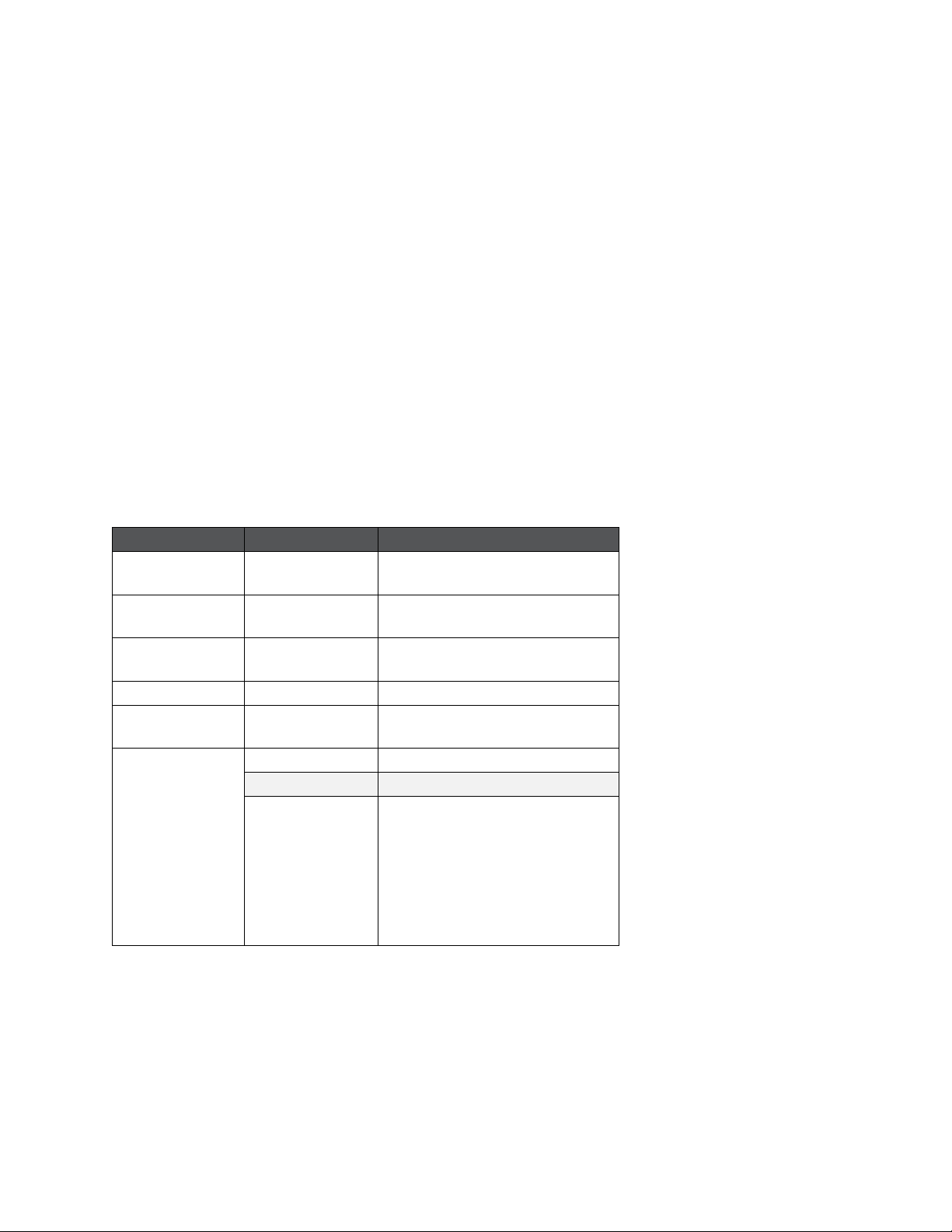
Example:
Below is an example of the DMX address configuration for an RGB DMX PAR64 light. The LC-1X only
controls the red, green and blue values of the light. Therefore, the remaining channels will be set to
a value of zero. If using a Talent DMX light purchased from the official Boomlights online store, refer
to the “Base Address” column on the table in section 2.4.1 to determine the channel to set the
starting address of the corresponding DMX light to. In order for the LC-1X to control the RGB colour
parameters of the light, the light’s DMX address should be set to “20”. To change the address of a
particular DMX light, refer to its user manual.
Channel
Value
Function
1
0 –255
RED
0% –100%
2
0 –255
GREEN
0% –100%
3
0 –255
BLUE
0% –100%
4
8 –255
COLOUR MACRO
5
0 –10
16 –255
NO FUNCTION
STROBING
6
0 - 31
NO FUNCTION
DIMMING CONTROL
32 –63
64 –95
96 –127
128 –159
160 –191
192 –223
224 –255
DIM TO BRIGHT
BRIGHT TO DIM
DIM TO BRIGHT TO DIM
COLOUR MIXING
3 COLOUR CHANGE
7 COLOUR CHANGE
SOUND ACTIVE

Page 8of 13
2.4.1 DMX Address Table
Model
Channel
Mode
Base
Address
Red
Green
Blue
Master
Strobe
Talent RGB LED
Baby Bar
(BL63)
3
Channel 20
0 - 255
0 - 255
0 - 255
N / A
N / A
Talent RBG LED
Slim PAR 64
(LP64LED-FLAT)
3
Channel 20
0 - 255
0 - 255
0 - 255
N / A
N / A
Talent RGB LED
Mini PAR 36
(LP12 LED)
5
Channel 20
0 - 255
0 - 255
0 - 255
0 - 255
0 - 255
2.5 Changing the Default Settings
2.5.1 Changing the MIDI Note DIP Switches
On the bottom of the LC-1X, you will find a pair of DIP switch arrays. Switches 1 to 4 of the first DIP
switch array control the MIDI channel the unit responds to while switches 5 to 7 control the DMX
address the unit transmits, which are reserved for custom configurations. The second DIP switch
array controls which MIDI notes the unit responds to.
By setting the DIP switches, you are effectively setting the MIDI note that will control the colour
green. The colours red and blue will always be the following 2 MIDI notes. For example, setting the
DIP switches to the binary value 0 (all switches in the down position), means that the unit will
respond to MIDI notes 0, 1 and 2 (C-2, C#-2 and D-2), which will be green, red and blue respectively.
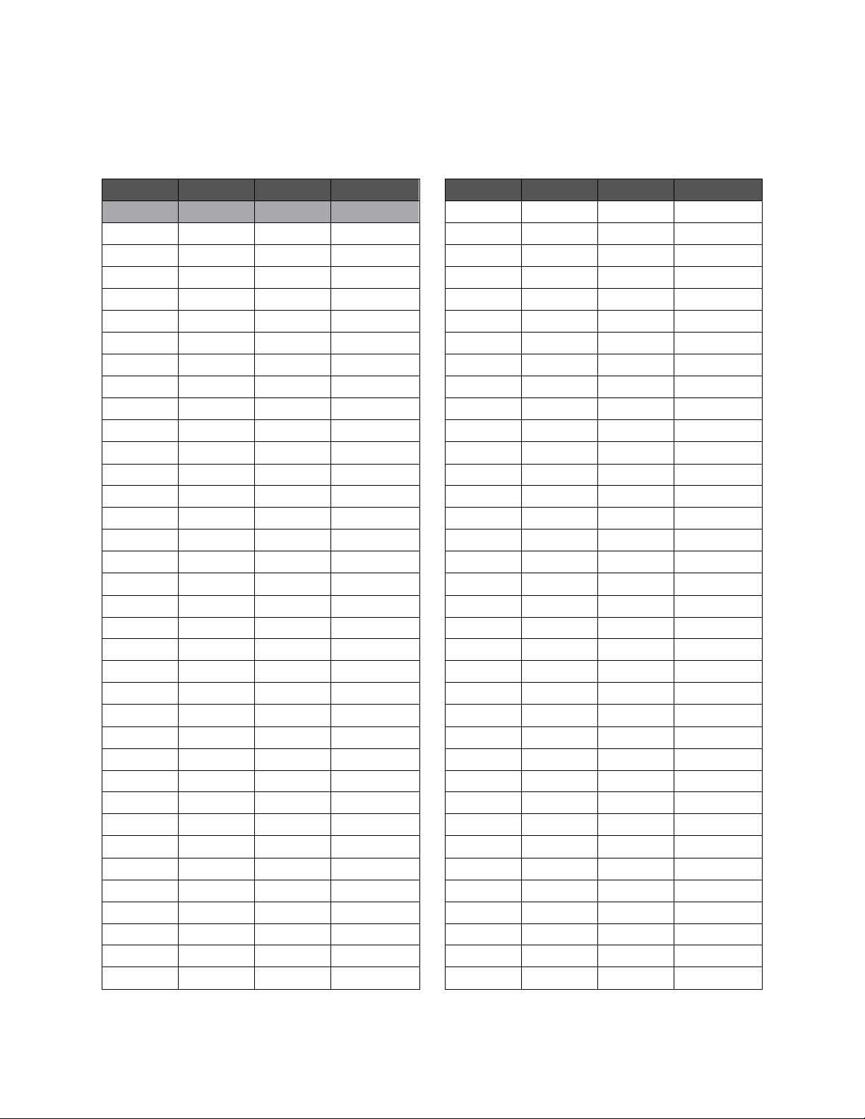
To set the DIP switches correctly to the desired MIDI note, refer to the “Binary” column on the table
in section 2.5.2. These 7 number sequences represent the individual DIP switch positions. When a
DIP switch is in the up position, it is considered “1” and, when it is in the down position, it is
considered “0”. These binary codes are used to configure the unit to respond to specific MIDI notes.
For example, if only DIP switch 1 is in the up position while the 6 remaining DIP switches are in the
down position (resulting in the binary code 1000000), MIDI note 64 (E3) will control the colour green.
Therefore, MIDI note 65 (F3) and 66 (F#3) will control the colours red and blue respectively.
Page 9of 13
It is important to note that any changes to the DIP switches must be done while the unit is powered
off, as the unit only checks the DIP switch settings during start-up.
2.5.2 MIDI Note DIP Switch Table
Note
Octave
Number
Binary
Note
Octave
Number
Binary
C
-2
0
0000000
C
1
36
0100100
C#
-2
1
0000001
C#
1
37
0100101
D
-2
2
0000010
D
1
38
0100110
D#
-2
3
0000011
D#
1
39
0100111
E
-2
4
0000100
E
1
40
0101000
F
-2
5
0000101
F
1
41
0101001
F#
-2
6
0000110
F#
1
42
0101010
G
-2
7
0000111
G
1
43
0101011
G#
-2
8
0001000
G#
1
44
0101100
A
-2
9
0001001
A
1
45
0101101
A#
-2
10
0001010
A#
1
46
0101110
B
-2
11
0001011
B
1
47
0101111
C
-1
12
0001100
C
2
48
0110000
C#
-1
13
0001101
C#
2
49
0110001
D
-1
14
0001110
D
2
50
0110010
D#
-1
15
0001111
D#
2
51
0110011
E
-1
16
0010000
E
2
52
0110100
F
-1
17
0010001
F
2
53
0110101
F#
-1
18
0010010
F#
2
54
0110110
G
-1
19
0010011
G
2
55
0110111
G#
-1
20
0010100
G#
2
56
0111000
A
-1
21
0010101
A
2
57
0111001
A#
-1
22
0010110
A#
2
58
0111010
B
-1
23
0010111
B
2
59
0111011
C
0
24
0011000
C
3
60
0111100
C#
0
25
0011001
C#
3
61
0111101
D
0
26
0011010
D
3
62
0111110
D#
0
27
0011011
D#
3
63
0111111
E
0
28
0011100
E
3
64
1000000
F
0
29
0011101
F
3
65
1000001
F#
0
30
0011110
F#
3
66
1000010
G
0
31
0011111
G
3
67
1000011
G#
0
32
0100000
G#
3
68
1000100
A
0
33
0100001
A
3
69
1000101
A#
0
34
0100010
A#
3
70
1000110
B
0
35
0100011
B
3
71
1000111

Page 10 of 13
Note
Octave
Number
Binary
Note
Octave
Number
Binary
C
4
72
1001000
C
7
108
1101100
C#
4
73
1001001
C#
7
109
1101101
D
4
74
1001010
D
7
110
1101110
D#
4
75
1001011
D#
7
111
1101111
E
4
76
1001100
E
7
112
1110000
F
4
77
1001101
F
7
113
1110001
F#
4
78
1001110
F#
7
114
1110010
G
4
79
1001111
G
7
115
1110011
G#
4
80
1010000
G#
7
116
1110100
A
4
81
1010001
A
7
117
1110101
A#
4
82
1010010
A#
7
118
1110110
B
4
83
1010011
B
7
119
1110111
C
5
84
1010100
C
8
120
1111000
C#
5
85
1010101
C#
8
121
1111001
D
5
86
1010110
D
8
122
1111010
D#
5
87
1010111
D#
8
123
1111011
E
5
88
1011000
E
8
124
1111100
F
5
89
1011001
F
8
125
1111101
F#
5
90
1011010
F#
8
126
1111110
G
5
91
1011011
G
8
127
1111111
G#
5
92
1011100
G#
8
-
-
A
5
93
1011101
A
8
-
-
A#
5
94
1011110
A#
8
-
-
B
5
95
1011111
B
8
-
-
C
6
96
1100000
C#
6
97
1100001
D
6
98
1100010
D#
6
99
1100011
E
6
100
1100100
F
6
101
1100101
F#
6
102
1100110
G
6
103
1100111
G#
6
104
1101000
A
6
105
1101001
A#
6
106
1101010
B
6
107
1101011

Page 11 of 13
2.5.3 Changing the MIDI Channel DIP Switches
Setting switches 1 to 4 on the first DIP switch array determines which MIDI channel the unit will
respond to. These DIP switches are set the same way in which the MIDI note DIP switches are set.
That is, when a DIP switch is in the up position, it is considered “1” and, when it is in the down
position, it is considered “0”. These binary codes are used to configure the MIDI channel in which the
unit will respond to. For example, if only DIP switch 4 is in the up position while the other 3 are in
the down position (resulting in the binary code 0001), the unit will respond to MIDI channel 2. Refer
to the “Binary” column on the table in section 2.5.4 for the DIP switch positions required to change
the unit’s designated MIDI channel. The default DIP switch setting is highlighted in grey.
Again, it is important to note that any changes to the DIP switches must be done while the unit is
powered off, as the unit only checks the DIP switch settings during start-up.
2.5.4 MIDI Channel DIP Switch Table
MIDI Channel
Binary
1
0000
2
0001
3
0010
4
0011
5
0100
6
0101
7
0110
8
0111
9
1000
10
1001
11
1010
12
1011
13
1100
14
1101
15
1110
16
1111
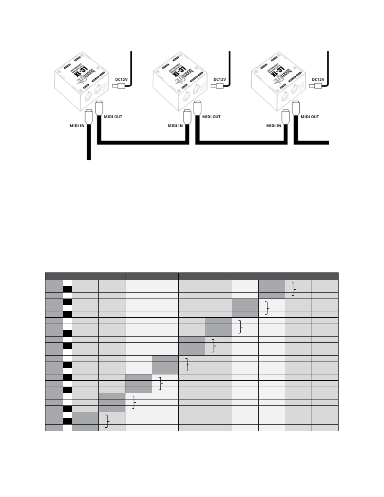
2.6 Linking Multiple Units Together
Multiple units can be linked together using the “MIDI In”and “MIDI Thru”connectors found on the
side of each unit. Using a standard MIDI cable, you can connect the “MIDI Thru”of the unit that is
receiving incoming MIDI data with the “MIDI In”of the other unit that you want to link. This same
process can be applied to link additional units as displayed in the diagram on the next page.
Page 12 of 13
You can assign each unit to different MIDI note ranges and control them via the same MIDI channel
by adjusting the MIDI note DIP switches accordingly. If you refer to the table in section 2.5.2, there
are 8 cells that are shaded grey, which represent the values you would set the DIP switches to if you
were to link 8 LC-1X units together with the intention of controlling them independently. More
specifically, this would allow you to separately control a combination of 8 sets of LED strips and/or 8
DMX universes. The following table depicts the specific MIDI note assignments of each LC-1X unit
and their corresponding colours. Of course, you can assign each unit to whichever MIDI notes you
desire. This is simply an example of a possible configuration in which the first 24 MIDI notes are
assigned concurrently to 8 units. Ultimately, you can use as many LC-1X units as the MIDI scale will
allow.
4 / 4
1
1.2
1.3
1.4
2
B-1
NOTE 23
B
A#-1
NOTE 22
R8
A-1
NOTE 21
G
G#-1
NOTE 20
B
G-1
NOTE 19
R7
F#-1
NOTE 18
G
F-1
NOTE 17
B
E-1
NOTE 16
R6
D#-1
NOTE 15
G
D-1
NOTE 14
B
C#-1
NOTE 13
R5
C-1
NOTE 12
G
B-2
NOTE 11
B
A#-2
NOTE 10
R4
A-2
NOTE 9
G
G#-2
NOTE 8
B
G-2
NOTE 7
R3
F#-2
NOTE 6
G
F-2
NOTE 5
B
E-2
NOTE 4
R2
D#-2
NOTE 3
G
D-2
NOTE 2
B
C#-2
NOTE 1
R1
C-2
NOTE 0
G

Page 13 of 13
3.0 CURRENT LIMIT
Each LC-1X has a current limit of 2A for a connected LED strip. This works out to a maximum LED
strip length of 96”. If this length is exceeded, the unit may power off due to the internal resettable
fuse. In this case, the unit will power back up once the LED strip exceeding 96” in length is removed.
This current limit does not apply to DMX lights since each DMX light will have its own power supply.
4.0 TROUBLESHOOTING
Issue: Changed the DIP switches to use other MIDI notes or to use another MIDI channel, but the
unit is not responding to the new changes and is continuing to use the original note and channel
assignments.
Solution: Make sure the unit is powered off when changing the MIDI notes or MIDI channel DIP
switches, as the unit only checks for new DIP switch settings during start-up.
Issue: Changed the MIDI notes or MIDI channel DIP switches while the unit was powered off, but,
after start-up, the unit is still not responding to the new MIDI notes or MIDI channel selected.
Solution: Power off the unit and check to make sure the DIP switches are fully set in their intended
positions. Sometimes, if you do not press hard enough when moving a DIP switch, it can get stuck in
a middle position, which will result in the wrong MIDI notes or MIDI channel being selected.
Issue: DMX light is connected to the unit and the indicator light is displaying the intended colour, but
the DMX light is not illuminating.
Solution: Ensure that the DMX cable connected to the unit’s “DMX Out”is connected to the DMX
light’s “DMX In”. If the DMX cable is connected correctly, double check to make sure that the base
address of the DMX light is set to “20”. Most RGB DMX lights will comply to the LC-1X’s default 3-
channel configuration. However, if you are using another type of DMX light, please contact
Boomlights for support as the LC-1X is also equipped to accommodate other DMX channel
configurations. They will simply require the DMX DIP switches to be set to a different binary code.
5.0 SPECIFICATIONS
LC-1X: 1-CH LIGHTING CONTROLLER
Controls: 2x DIP Switch Arrays (MIDI Channel / DMX, MIDI Note)
Indicators: Power / Output Colour Indicator Light
Connectors: DC12V Input, MIDI Thru, MIDI Input, LED Output, DMX Output,
Power Supply: DC12V 2A 90~240VAC
Maximum Current Draw: 2A
Dimensions: 2.5” x 2.5” x 1.625” (64 mm x 64 mm x 41 mm)
Weight: 0.23 lbs (0.1 kg)
Table of contents
Other BOOMLIGHTS Lighting Equipment manuals


