Booth EXL651 User manual
Product Manual
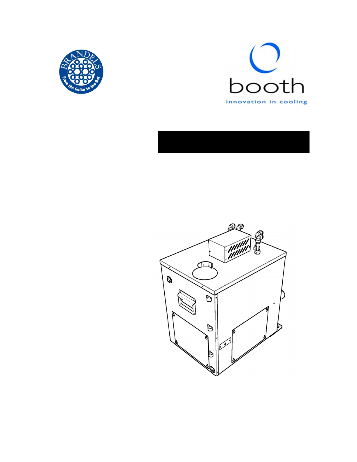
EXL651 Still and Carbonated
Water Cooler
Part Number 3B6220 Issue A (24/05/16)

2
Contents
Section Page
Section Page
Introduction & Specification 2 Fault Finding 8
Installation & Commissioning
3 Wiring Schematic 9
Spare Parts 7 Removal, Transportation
and Disposal
10
Introduction
The EXL651 is an ice-bank cooler designed for installation in a cupboard under a worktop,
and incorporates two water cooling coils. It can either be installed in conjunction with a
separate ambient carbonator, the EXL171, to provide still and carbonated water, or on its own
to provide still water only. The pack includes air duct components that must be installed if the
chiller is installed in an otherwise unventilated space.
Specification
Dimensions 330mm(W)
482mm(D)
522mm(H)
Compressor Cubigel
GL60TB
Dry Weight
32.5kg
This product contains fluorinated
greenhouse gas with a GWP of 1300
in an hermetically sealed system
Wet Weight 45.0kg
Supply
230Vac/50Hz
Refrigerant
R134a,
12
0
g
Rated Input 300W Climatic Class N
Rated Current 2A
Fuse Rating 5A Net cooling power
24°C ambient, during
recovery.
570W
IP Rating N/A Nominal ice bank 5kg
Contents
Introduction and Specification

3
Installation and Commissioning
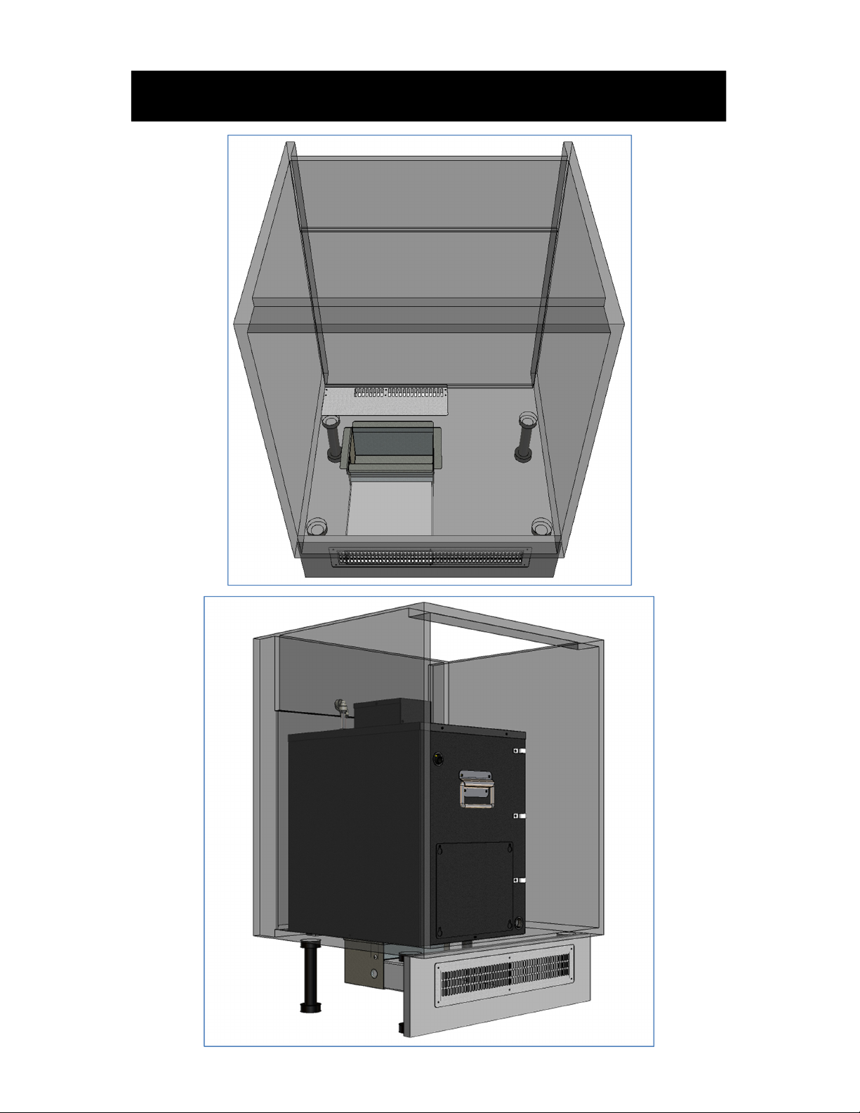
•The EXL651 is designed to be fitted in a cupboard under a worktop, and is supplied
with parts to ensure adequate ventilation is provided. It is essential that these be
used if the unit is to be fitted into an enclosed compartment, if not, this will
seriously affect the reliability of the fridge and will invalidate the warranty. It is
also possible that the heat generated by the fridge will distort the carcass of the
cupboard. The hot exhaust air is ducted down through the base of the cabinet, and
out of the front of the kick-space. Cooler air is drawn into the cupboard through a vent
at the rear, drawing air from the kick space. A facing grill is provided for the kick board
that provides for the location of the exhaust duct, and, if required, additional ventilation
for the kick-space. This additional ventilation will only be required if the kickboard is
sealed to the cabinets, in the majority of cases, there will be sufficient natural
ventilation.
•Templates are provided to help in the location of ventilation openings that need to be
cut into the cabinet base, and kick space, and are designed to allow the EXL651 to be
installed against the left hand side of the cabinet, viewed from the front.
•Align template 3B4614 with the rear left hand side corner of the cabinet, and mark
through the corners of the two cut-outs. Cut out the openings taking care not to cut into
any pipes or cables that may be located under the cabinet.
•Align template 3B4615 with the top left corner of the kick board for the cabinet being
used. Again, mark through and cut-out the area for the exhaust duct, and mark the
fixing positions of the fixing holes.
NOTE: For additional dimension information on cut out sizes and positions please refer to
page 6 of this manual.
•Insert the right angled duct into the large hole in the base of the cabinet, and fix the
rear grill in position over the other gap cut previously.
•Insert the plastic air duct from the front, and ensure it is fully engaged with the right
angled duct. Mark the position on the plastic duct that aligns with the outside face of
the kick board, remove and cut to length.
•If the kick board is sealed to the cupboard and floor, additional ventilation will be
required. Offer up the front grill, aligning the fixing holes, and mark through the extent
of the ventilation openings. Now extend the opening, taking care that the height of this
part of the cut-out is less than that where the exhaust duct is located, this will ensure
the exhaust duct is held in position.
•Refit the exhaust duct, and fasten the front grill in position.
Installation and Commissioning

4
•Place the EXL651 into the cabinet with the rubber bump-stops to the rear, aligning the
left side to the left side of the cabinet. Push in until the bump stops contact the rear of
the cabinet. The exhaust grill on the bottom of the machine will now align with the cut-
out in the base of the cabinet.
•Place a suitable container under the bath overflow, a small plastic bottle is provided
for this purpose.
•Fill the bath with cold water through the opening on the top of the machine until water
is displaced from the over flow.
•Connect power to the machine and switch on. The fan and compressor will start, and
the machine will start to cool down.
•The machine can now be connected to the other components of the water system, and
once a full ice bank is produced, the fans and compressor will switch off, and the
machine is ready for use.
Installation and Commissioning
5
Installation and Commissioning
6
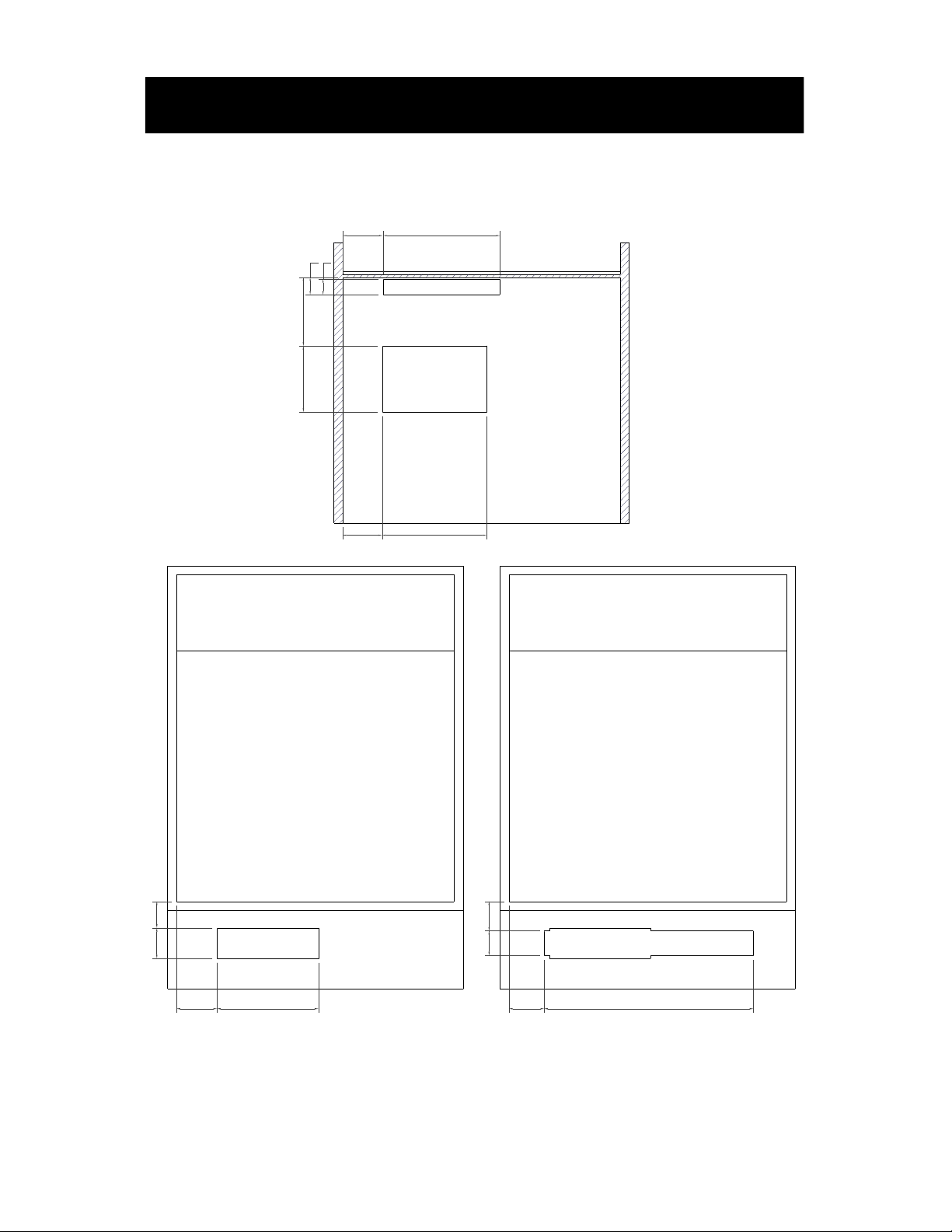
80 212
134 140
36 32
23882
82
54
206
62
Top View
Front View
Standard Cutout
72
60
425
50
Front View
Extended Cutout
All dimensions are based around a standard 600mm wide kitchen cabinet.
Installation and Commissioning
7
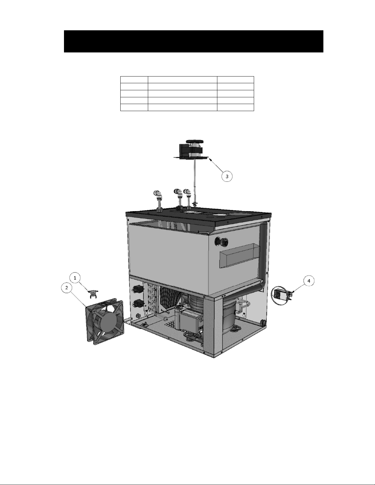
Item No
Description
Part No
1 High Side Protector 3B3963
2 Axial Fan 1B5514
3 Agitator Assembly 1A5237
4 Control Thermostat 1A4714
Spare Parts

8
Prior to any fault finding, please ensure all water connections to the chiller are sound and that the
incoming water supply is turned on. Also ensure that all electrical connections to the chiller and in
the chiller are secure and in good condition, the power is on and that the chiller has had adequate
time to reach operating temperature.
NOTE: When checking electrical connections ensure mains power is switched off.
No Drinks Water supply Check connections to water supply.
Check water supply is turned on.
Check system for blockages.
Frozen product coil Check thermostat probe is correctly located into the
bath probe well.
Check the agitator is running. If supply voltage is
present renew agitator assembly.
If agitator is running with no water agitation check
agitation blades.
Warm Drinks Insufficient air flow through
the fridge.
Check that the condenser is not blocked.
Check for blockages and obstructions to ventilation
grills.
If in enclosed cabinet check supplied ventilation kit
is fitted and can ventilate to cool air supply.
Cooling Fans Not running Check supply to cooling fans.
If supply present replace fans.
If supply not present check connections,
thermostat, high side protection and fuse.
Compressor not running Check supply to Compressor.
If supply present return for repair.
If supply not present check connections, thermostat,
high side protection and fuse.
Fridge failure If compressor & fan are running and there is no
cooling, return for repair.
Fault Finding
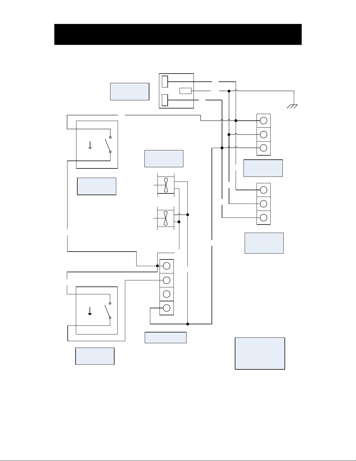
9
G/Y
BR
L
N
FUSED MAINS
PLUG
BU
BR
G/Y
BR
L
NC
E
N
WH
WH
YE
BU
BU
BU
AGITATOR IEC
CONNECTOR
CARBONATOR
IEC
CONNECTOR
CONDENSOR
FANS
COMPRESSOR
CONTROL
THERMOSTAT
HIGH SIDE
PROTECTOR
NOTE
SOME EARTH
CABLES (G/Y)
OMITTED FOR
CLARITY
Wiring Schematic
10
Important: Before removal from the installation, ensure all electrical, product and gas
connections are disconnected.
Disposal of Scrap Units
It is illegal to simply scrap a refrigeration unit. Before a unit can be scrapped it must first have the gas
removed by a specialist using special equipment. Please contact Booth Dispensers Ltd., who will be
happy to provide a quotation for disposal.
Transportation
Important: This unit must be transported in an upright position
As with all refrigeration systems, irreparable damage can be caused by laying the unit on its side or
even transporting upside down. Where the unit is transported by a carrier, the carton should always
be marked in a conspicuous manner, the correct upright position in which it must be handled.
If a unit has been transported incorrectly it should be placed in the correct upright position and left for
24 hours before attempting to run the system.
Failure to observe the above precautions could seriously damage the system, and would void any
warranty.
Removal, Transportation and Disposal
Booth Dispensers Ltd, Moor Park Avenue, Blackpool,
Lancashire, FY2 0LZ, UK
+44 1253 501800
Table of contents
Other Booth Water Dispenser manuals

Popular Water Dispenser manuals by other brands


Kenmore
Kenmore 625.388180 owner's manual

Water Control Corporation
Water Control Corporation BrassMaster Installation & operation manual

Haws
Haws H1107.8 Installation, operation & maintenance instructions

Murdock
Murdock A171.8FGVR Series Installation & maintenance instructions

Lancaster
Lancaster 7-LMC56-75B Installation, operating and service manual

Daewoo
Daewoo DAWS-10L user manual

Elkay
Elkay EZOTL FLEXI-GUARD Series Installation, care & use manual

Watts Premier
Watts Premier UC-2 Installation, operation and maintenance manual

IONICO
IONICO IQ Homeowner's manual

Hoshizaki
Hoshizaki DM-200B parts list

RAMTONS
RAMTONS RM/558 instruction manual

WaterLogic
WaterLogic WL400 Series Troubleshooting