Haws H1107.8 Guide

03/20 Model H1107.8 Page 1 of 7
1455 Kleppe Lane Sparks, NV 89431-6467 (775) 359-4712 Fax (775) 359-7424
No. 0002080221 (15)
Model H1107.8
Water Cooler
INSTALLATION, OPERATION
&
MAINTENANCE INSTRUCTIONS
LIMITED WARRANTY
HAWS warrants that this specific product is guaranteed against defective material or
poor workmanship for a period of one year from date of shipment. HAWS liability
under this warranty shall be discharged by furnishing without charge F.O.B. HAWS
Factory any goods, or part thereof, which shall appear to the Company upon
inspection to be of defective material or not of first class workmanship, provided that
claim is made in writing to Haws within a reasonable period after receipt of the
product. Where claims for defects are made, the defective part or parts shall be
delivered to the Company, prepaid, for inspection. HAWS will not be liable for the
cost of repairs, alterations or replacements, or for any expense connected therewith
made by the owner or his agents, except upon written authority from HAWS, Sparks,
Nevada. HAWS will not be liable for any damages caused by defective materials or
poor workmanship, except for replacements, as provided above. Buyer agrees that
HAWS shall not be liable for general, special, or consequential damages claimed to
arise under the contract of sale. The drinking fountain manufactured by HAWS is
warranted to function if installation and maintenance instructions provided are
adhered to. The units also must be used for the purpose for which they were
intended.
NO OTHER WARRANTIES EXPRESSED OR IMPLIED ARE AUTHORIZED, PROVIDED
OR GIVEN BY HAWS.
CAUTION! Prior to making any electrical connections, verify with a voltmeter that power from the
service panel is off.
NOTE TO INSTALLER: Please leave this information with the Maintenance Department.
Haws electric water coolers are not designed or recommended for outdoor or corrosive
environments such as enclosed chlorinated pool areas.
Consideration must be made at the time of installation to adhere to state and/or local codes and
environmental/atmospheric conditions such as, but not limited to, dust, corrosion, freezing, etc.
These conditions will void the warranty.

03/20 Model H1107.8 Page 2 of 7
RECOMMENDED TOOLS: Hack saw, pipe joint sealant, screwdriver, level, 12" adjustable
wrench, 10" pipe wrench, 5/64“ hex key wrench, 9/16”, 1/2", 7/16” socket wrench or open
end wrench.
LOCATION OF UNIT: The Model H1107.8 Cooler is a wheelchair accessible drinking water
facility. The height dimensions shown, meet current ADA requirements. When installing this
unit, local, state or federal codes should be adhered to. If height other than shown is
required, then dimensions must be adjusted accordingly.
SUPPLY LINE: The minimum recommended line size is 1/2“IPS with 30-90 psi (2-6 ATM)
flowing pressure. Where sediment or mineral content is a problem, an inlet filter is
recommended.
PLUMBING CONNECTIONS: Inlet is 3/8” O.D. push-in type fitting. Waste trap outlet is
female 1-1/4” IPS.
ELECTRICAL CONNECTIONS: 115VAC, 60HZ, 4.7 AMPS. Chiller wired direct to incoming
line, by others.
PARTS LIST
MODEL PACKAGE
QUANTITY
ITEMS INCLUDED
MTGFR.7
1
Mounting Frame (Required –Sold
Separately)
3
#10 Sheet Metal Screws
HCR8
1
Chiller
H1107.8
1
Bowl Assembly
1
Package supply tubing assembly and
2 fittings
1
Panel-bowl back
1
Grille
1
Trap 1-1/4” IPS
1
Package of two each: grille
attachment, attachment clips, clip
nuts, #10 sheet metal screws and 6-32
screws
4
5/16 -18 retainer nuts
4
5/16 –18 x 1 hex head screws
SHOULD YOU EXPERIENCE DIFFICULTY WITH THE INSTALLATION OF THIS
MODEL PLEASE CALL:
TECHNICAL SUPPORT: 1-800-766-5612
FOR CUSTOMER SERVICE: 1-888-640-4297

03/20 Model H1107.8 Page 3 of 7
INSTALLATION PROCEDURE
GENERAL NOTES:
The Model H1107.8 Water Cooler assembly requires installation of the mounting frame as
described in Steps 1 - 2, then mounting the fountain bowl assembly as described in Steps 3 - 6,
and finally completing chiller water and electrical connections and starting chiller per Steps 7 -
11. First check that all required parts are received.
Grounding may cause electrical feedback into the electric drinking fountain causing an
electrolysis, which creates a metallic taste or an increase in the metal content of the
water. This condition can be avoided by using dielectric couplings in the assembly. The
waste line, which is supplied by the installer, should also have a dielectric (plastic)
coupling to completely isolate the assembly from the building plumbing system.
NOTES:
1. For all plastic push-in type fitting connections, only connect NSF-61 copper or
plastic tubing. Stainless steel or glass tubing is not recommended. The
following assembly instructions must be followed to ensure a watertight
connection:
a. Cut tubing square and clean.
b. Mark from end of tube the length of insertion (See table below).
c. Push tube into the fitting until it bottoms out.
d. To remove, depress collet and pull tubing out.
Tube Sizes
O.D.
Tolerance
Insertion Depth
1/4”
±.005”
11/16”
3/8”
±.005”
3/4”
1/2”
±.005”
7/8”
STEP 1: Provide wall opening as detailed in Installation Drawing. Frame must be positioned
such that frame flanges overlap and butt against finished wall surface. Mounting
holes are provided for #6 sheet metal screws. After frame is positioned in wall,
swing chiller support tray into position (See Installation Drawing), align tray holes
with holes in frame and fasten with #10 sheet metal screws. Mounted frame must
support 50-pound chiller in addition to fountain weight and user generated forces.
STEP 2: Install waste, supply and electrical lines in locations shown in Installation Drawing.
Waste and supply lines may be installed for either rear or side entry. Verify proper
waste, supply, electrical and frame locations. Use level to verify horizontal and
vertical frame mounting to insure proper bowl drainage.
STEP 3: Installation Drawing shows fountain bowl, back panel and grille locations. Unpack
bowl and remove bottom plate using 5/64” hex-allen wrench. Install back panel on
frame with narrower edge to bottom. Position nut retainers into mounting frame.
Install bowl/bracket assembly onto panel using four 5/16-18x1 hex head screws hand
tightened.
STEP 4: Remove 1-1/4” IPS outlet elbow from trap as supplied. Install elbow inside frame
onto waste stub-outs.
STEP 5: Assemble waste trap onto bowl strainer using seal washer provided and tighten nut
hand tight.

03/20 Model H1107.8 Page 4 of 7
INSTALLATION PROCEDURE …
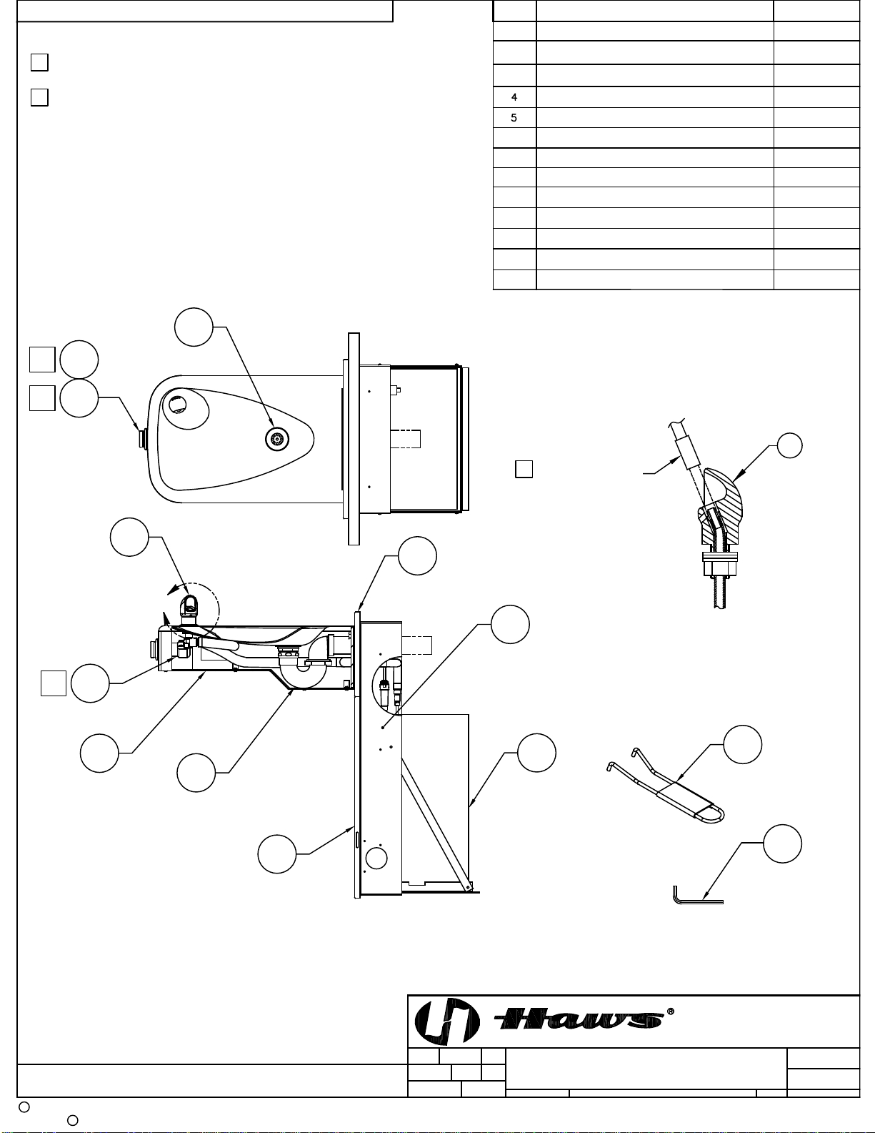
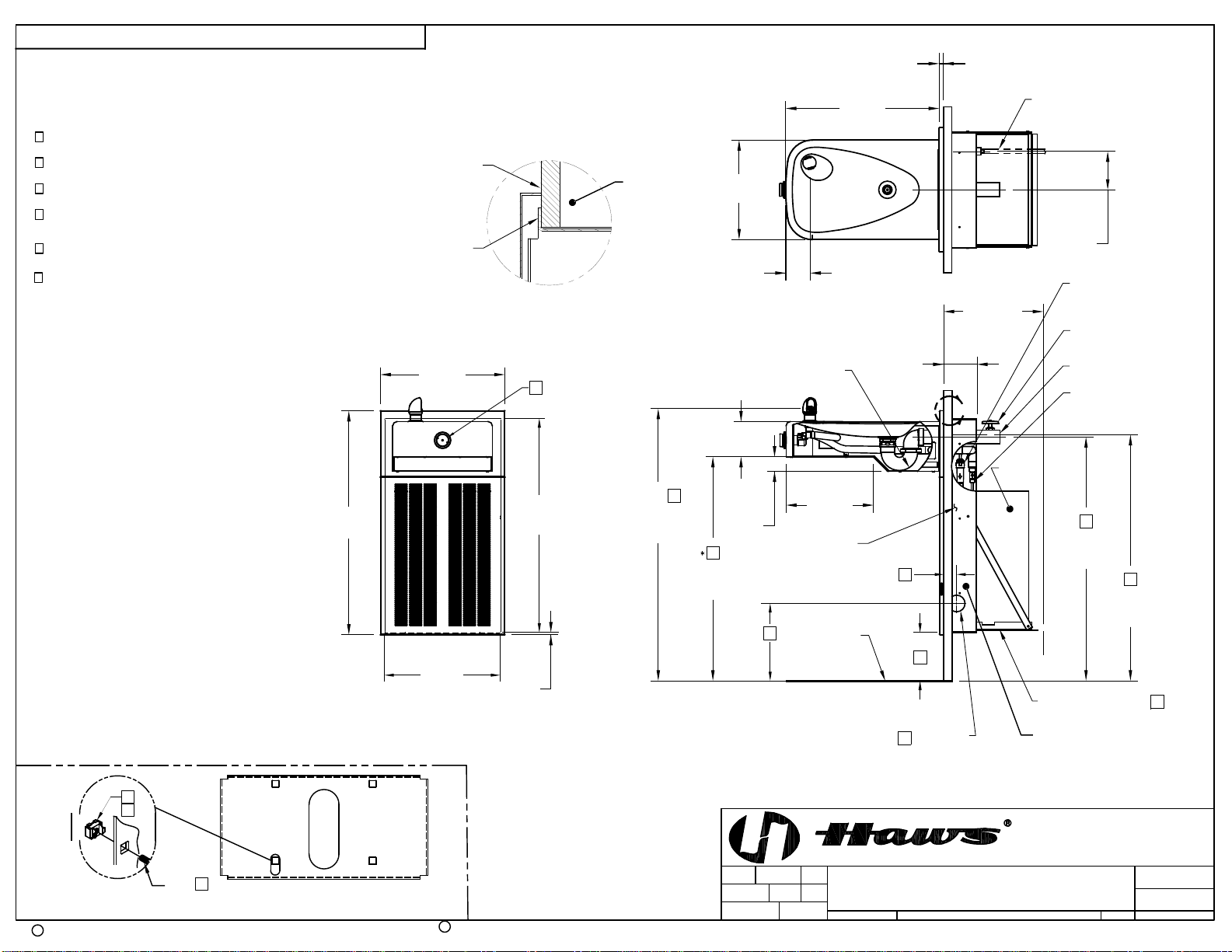
STEP 6: See Figure 1 for detail section view of side screw grille attachment. Unpack grille and
insert upper lip behind bottom of back panel, align sides and hold up flush to bottom
of back panel. Hold grille against wall and mark centers of grille side slots on wall.
Masking tape may be used to prevent finished wall damage from mark. Install the “s”
clips in mounting frame using #10 sheet metal screws into pre-drilled holes on lower
end of each side of frame. Tighten #10 screw while holding “s” clips centered on wall
marks. Check grille fit by installing grille and partially tightening #6-32 socket head
screws through side of grille. Ensure proper panel and grille alignment, then tighten
the four 5/16-18x1 hex head screws.
STEP 7: Unpack and remove chiller from carton. Remove front panel screws and panel. Do
not remove insulating putty and foam from copper tubes or Styrofoam insulation from
evaporator coil. Remove any inner packing, which may be around compressor. If
applicable, remove junction box cover and electrical knock out on lower right side of
housing. Install fittings (supplied) on chiller inlet and outlet tubes (see Installation
Drawing).
STEP 8: Thoroughly flush supply line to remove all foreign matter. Remove the grille and
connect the 1/2" IPS supply screwdriver stop (not supplied) to stub-out in wall. Place
chiller on chiller support tray against right hand side, fully to rear, with condenser
(open panel) side facing to front., Install supply 3/8” O.D. tubing (not supplied)
between screwdriver stop and chiller inlet. (Cut tubing to proper length, and follow
general notes for proper connection procedures for push-in type fittings). Tubing
insulation is not normally required on inlet side of chiller. Install insulated tube
between fountain and chiller outlet. Open screwdriver stop wide open while
checking for leaks at all connections. Also check waste for leaks.
STEP 9: Adjust bubbler stream height using a small flathead screwdriver inserted through a
hole in the center of the push button for increased flow turn clockwise and for
decreased flow turn counterclockwise. If flow problems arise, see troubleshooting
guide for additional instructions to correct problem. Bubbler stream may lower during
short break-in period. Set initial stream height a little high to minimize or eliminate
the need for break-in period readjustment.
FIGURE 1

03/20 Model H1107.8 Page 5 of 7
INSTALLATION PROCEDURE …
STEP 10: Verify that electrical power is off and power supply voltage, phase and cycle match
specifications printed on chiller label. In accordance with local codes, wire directly to
incoming lines at internal chiller junction box. Verify that all of the inner packing is
removed and hand rotate fan blade to verify free rotation. Reattach the chiller front
panel. Turn power on and verify that the chiller cycles off after water reaches proper
temperature. Finally check for leaks.
STEP 11: Install grille and tighten outer side screws. Verify there is chilled water out of bubbler.
MAINTENANCE
STEP 1: Periodically clean the strainer located inside the valve body. Refer to 5874 Series
Valve Manual for more information.
STEP 2: The condenser fins on chiller should be periodically cleaned with a brush, an air hose
or a vacuum cleaner. Care should be taken not to bend or deform the condenser
fins.
STEP 3: The chiller temperature control is factory set for 50 º F water under normal
conditions. For colder water, adjust the control clockwise. For warmer water, turn
counterclockwise. Remove front chiller panel for access to temperature control.
After adjustment allow unit to cycle off before checking outlet water temperature.
TROUBLESHOOTING
PROBLEM
REPAIR CHECKLIST
1.
Insufficient bubbler flow.
1a.
Check that inlet screwdriver stop valve is
in wide-open position.
b.
Verify minimum 30 psi flowing supply
pressure.
c.
Clean strainer. See 5874 Series Valve
Manual.
d.
Adjust valve to increase flow. Use front
adjust screw or see 5874 Series Valve
Manual.
2.
Water too warm or cold.
a.
Adjust chiller temperature control,
clockwise for colder water.
For more information about Haws products, see our website: www.hawsco.com
© 2020 Haws®Corporation –All Rights Reserved
HAWS® and other trademarks usedin these materials are the exclusive property of Haws Corporation.

BOTTOM PLATE
SPANNER WRENCH P/N
STRAINER ASSY
BUBBLER HEAD
BUTTON, PUSH, FLANGED WITH VALVE
BUTTON, PUSH, FLANGED
TRAP
REMOTE CHILLER
GRILLE 1107L
MOUNTING FRAME
BACK PANEL
12
12
KEY HEX F/PINNED HEX
13
A
11
10
9
8
7
6
3
2
1
5
3
11
7
81
2
410
9
6
APPROVED
DRAWN
PART NUMBER
SCALE: SHEET OF
REVISION
DRAWING TYPE: SIZE: A
BYECN NO.
PAGE
DATE
DATE
ECN:
REVISED PER
CHKD
Haws Corporation - All Rights Reserved
HAWS and other trademarks used in these materials are the exclusive property of Haws Corporation.
CR
MODEL(S)
1455 KLEPPE LANE
SPARKS, NEVADA 89431
(775) 359-4712 FAX (775) 359-7424
E-MAIL: [email protected]
WEBSITE: WWW.HAWSCO.COM
ITEM DESCRIPTION
THIS DOCUMENT IS TRUE AND CORRECT AT TIME OF PUBLICATION. CONTINUED PRODUCT IMPROVEMENTS
MAKE SPECIFICATIONS AND MEASUREMENTS SUBJECT TO CHANGE WITHOUT NOTICE.
WHEN ORDERING PARTS PLEASE SPECIFY MODEL NUMBER.
PART NO.
C.FENNER
10-25-06
15
0002080221
H1107.8
N/A
11
FV
06/26/20
.
DP
6 OF 7
PARTS BREAKDOWN
5545
2020
FV
PBM1107
0006983506
6462
5703M
5874PBF
PBA6
0005982900
HCR8
0002626550
MTGFR.7
BP7
0002981127
PARTS BREAKDOWN
NOTES:
1 5874PBF (ITEM 7) INCLUDES VRK5874 CARTRIDGE ASSEMBLY
(ITEM 13) AND PBA6 FLANGED PUSH BUTTON (ITEM 6).
2 ENSURE TUBE IS DISCONNECTED FROM PUSH BUTTON
VALVE BODY PRIOR TO REMOVAL. APPLY ONE DROP OF
LOCTITE 222MS TO NOZZLE THREADS PRIOR TO
FASTENING BACK ONTO BUBBLER HEAD. RE-ATTACH
TUBE TO VALVE.
VRK5874VALVE REPAIR KIT
REF
8
REMOVE INSERT
WITH 5/16 HEX SOCKET
(NOT SUPPLIED)
2
ROTATED 90° INTO VIEW
DETAIL A
13
1
1
1
**
** REQUIRED - SOLD SEPARATELY

4-5/8
[117mm]
CHILD/ADULT/
ADULT STANDING
WASTE
CHILD/ADULT/
ADULT STANDING
SUPPLY
12
[305mm]
CLEARANCE
10-3/4
[273mm]
27
[686mm] 1-3/4
[44mm]
CHILD/ADULT/
ADULT STANDING
BUBBLER
CHILD/ADULT/
ADULT STANDING
FOUNTAIN
4-1/4
[108mm]
(1/4)
[7mm]
4
4
ELECTRICAL
ACCESS
FLOOR LINE
15
[381mm] 3
WIDTH
FRAME
MOUNTING
4
[102mm]
A
18-1/2
[470mm]
(SUPPLIED)
1-1/4" IPS TRAP
CHILLER SUPPORT TRAY
1-1/4" IPS WASTE
(NOT SUPPLIED)
SUPPLY STOP AND
3/8" OD TUBING
(NOT SUPPLIED)
FLANGE
FRAME
WALL FACE
BOWL MOUNTING DETAIL
5
SCREW 6
6
8
*
8
*
*8
*
8
8
*
1/2" IPS SUPPLY
(NOT SUPPLIED)
2-7/8
[73mm]
1/2
[13mm]
STUD
DETAIL A
4
14
INLINE STRAINER,
1/4" OD TUBE X
3/8" OD TUBE
INLET (SUPPLIED)
(SUPPLIED)
3/8" OD TUBING,
INSULATION,
HCR8
CHILLER
25-13/16
[656mm]
ROUGH-IN
14
[356mm]
ROUGH-IN
NOTES:
3 REFER TO 5874 SERIES OPERATION AND MAINTENANCE MANUAL FOR
PUSH BUTTON AND VALVE INSTALLATION/MAINTENANCE INSTRUCTIONS.
4 REFER TO MTGFR.7 INSTALLATION DRAWING FOR FRAME
ROUGH-IN DIMENSIONS.
2. WHEN INSTALLING THIS UNIT, LOCAL, STATE, OR FEDERAL CODES SHOULD BE
ADHERED TO. FOR INSTALLATION HEIGHTS OTHER THAN SHOWN, DIMENSIONS
MARKED ( * ) MUST BE ADJUSTED ACCORDINGLY.
1. HOLD ROUGH-IN DIMENSIONS ± 1/8" (3.2mm)
5 INSERT 5/16"-18 PANEL NUT RETAINERS FROM OPPOSITE
SIDE AT LOCATIONS SHOWN.
6 FOUNTAIN REMOVAL: FIRST REMOVE SCREWS AND THEN
SQUEEZE CLIPS ON NUT RETAINER TO POP OUT. INSTALL
IS REVERSE OF REMOVAL.
7 ALIGN HOLES IN CHILLER SUPPORT TRAY WITH HOLES IN FRAME
AND FASTEN WITH #10 SHEET METAL SCREWS.
ADULT STANDING HEIGHT:
WASTE: 34-3/4" (883mm)
SUPPLY: 34-5/8" (879mm)
FOUNTAIN: 32-1/2" (826mm)
BUBBLER: 39-3/8" (972mm)
FRAME: 11-5/8" (384mm)
ADULT WHEELCHAIR HEIGHT:
WASTE: 29-1/4" (743mm)
SUPPLY: 29-1/8" (740mm)
FOUNTAIN: 27" (686mm)
BUBBLER: 32-7/8" (832mm)
FRAME: 6-1/8" (156mm)
CHILD WHEELCHAIR HEIGHT:
WASTE: 26-1/4" (667mm)
SUPPLY: 26-1/8" (664mm)
FOUNTAIN: 24" (610mm)
BUBBLER: 29-7/8" (756mm)
FRAME: 3-1/8" (79mm)
8 ROUGH-IN DIMENSIONS FOR FOUNTAIN HEIGHTS:
IMPORTANT: MOUNTING
FRAME MUST BE INSTALLED
SO THAT LIP OF FRAME SITS
AGAINST FINISHED WALL FACE.
MTGFR.7
MOUNTING FRAME
APPROVED:
DRAWN:
PART NUMBER
SCALE: SHEET OF
REVISION
DRAWING TYPE: SIZE: A
BY:ECN NO.
PAGE
DATE:
DATE:
ECN:
REVISED PER
CHK'D.:
Haws Corporation - All Rights Reserved. HAWS and other trademarks used in these materials are the exclusive property of Haws Corporation.
CR
MODEL(S)
1455 KLEPPE LANE
SPARKS, NEVADA 89431
(775) 359-4712 FAX (775) 359-7424
E-MAIL: [email protected]
WEBSITE: WWW.HAWSCO.COM
THIS DOCUMENT IS TRUE AND CORRECT AT TIME OF PUBLICATION. CONTINUED PRODUCT IMPROVEMENTS
MAKE SPECIFICATIONS AND MEASUREMENTS SUBJECT TO CHANGE WITHOUT NOTICE.
C.FENNER
12-19-06
15
0002080221.D
H1107.8
N/A
11
FV
06/26/20
DP
7 OF 7
INSTALLATION
5545
2020
FV
[305 mm]
12
MOUNTING FRAME
MTGFR.7
REQUIRED -
SOLD SEPARATELY
Table of contents
Other Haws Water Dispenser manuals
Popular Water Dispenser manuals by other brands

TCF
TCF 3500pro3 installation manual

Aqua To Go
Aqua To Go Argento Cleaning instructions

GM Autoflow
GM Autoflow HW Series quick start guide

vo-water
vo-water duomatik evoline installation guide

Elkay
Elkay EZ Series Installation, care & use manual

Andrew James
Andrew James Chilled Drink Dispenser With Infuser user guide

Kenmore
Kenmore 625.38306 owner's manual

Kenmore
Kenmore 625.388180 owner's manual

Elkay
Elkay EZTL EZSTL8 1D Series Installation, care & use manual

InSinkErator
InSinkErator Hot1 The installation, care and use

Whirlpool
Whirlpool 8171413 installation instructions

vitapur
vitapur Classic VWD5276BLK Specification sheet