Booth TRM9HC User manual

Product Manual
TRM9HC
Water Cooler
Part Number 3B8108 Issue OR

2
Contents
Safety
The TRM9HC model uses a R290 (Care 40, Propane) refrigerant. Below are some
safety points which the end user must adopt to mitigate the risk of unsafe conditions
arising.
Service must only be carried out by a suitably qualified refrigeration engineer.
The unit must be isolated from the electricity supply before removal of the
covers.
Do not damage/puncture the refrigeration circuit.
This unit is not intended for use in lobbies or locations of egress, such as
hallways or public corridors.
Ventilation openings must be clear of obstructions.
There must be a gap of at least 100mm between the appliance and a wall or
other restriction.
Where components are replaced, the new component must be of the same
type.
Operate the unit within (ambient) operating temperatures; 16⁰C to 38⁰C.
Introduction
The TRM9HC is a dry block chiller designed to provide chilled still water by passing water
through a stainless steel water coil in the “cold block”. The TRM9HC in standard
configuration is designed as a single product chiller with an option of two depending on
targeted drink temperature.
Important: It is essential that the TRM9HC be turned off during cleaning to prevent
the cleaning fluid in the product line from freezing.
Section
Page
Section
Page
Safety, Introduction & Specification
2-3
Fault Finding
9
Installation &
Commissioning
4
Replacement Parts
10
Cleaning
5-6
Removal, Transportation
and Disposal
11
Schematics
7-8
Introduction and Specification

3
Specification
Dimensions
470mm(W)
425mm(D)
260mm(H)
Compressor
Cubigel
NLY12RAa
Dry Weight
27Kg
This product contains fluorinated
greenhouse gas with a GWP of 3 in an
hermetically sealed system
Supply
220-240Vac/50Hz
Climatic Class
N
Power
Consumption
168W
Refrigerant
290a 55g
(0.055Kg)
Introduction and Specification

4
1. The TRM9HC unit should be located on a firm level surface capable of holding the
weight, as close to the dispense point as possible, and orientated so that the on/off
switch and Eliwell control are accessible. Ensure at least 100mm of space is left all-
round the unit to allow adequate airflow for cooling.
2. Connect using John Guest fittings to “Product In” on the front of the cooler.
3. Connect using John Guest fittings to “Product Out” on the front of the cooler and feed
the insulated product line to the dispense tap.
Note: At this stage do not connect the unit to the electrical supply.
4. Connect the chiller to the water supply and open the mains supply isolation valve.
5. Activate the still water dispense until all air has been purged from the system.
6. Once all air has been purged from the system, connect the unit to the electrical supply
and turn on. After a short delay the compressor and fans will start.
7. After approximately 10 minutes, the compressor and fan will stop as the chiller has
reached its normal operating temperature. Note: The time taken for the chiller to
reach operating temperature will vary depending on ambient temperature,
humidity and the temperature of the incoming water supply.
8. Maintenance: Wipe occasionally with damp cloth.
9. If compressor or thermostat problems occur the control will shut the compressor off
and display an error code. This should be quoted when requesting assistance.
Product Connections
Connection
Connection Size/Type
Product In
1/2” John Guest Speed Fit
Chilled Product Out
1/2” John Guest Speed Fit
Installation and Commissioning
Product Out
Product In

5
Important:
The frequency of the following cleaning procedures should be
determined locally and may vary depending on machine usage and
environmental conditions.
Warm water should be no higher than 45°C.
After any cleaning procedure, dispense 1 litre of water from each tap to
ensure any cleaning residue is flushed out.
Routine Clean - Use the appropriate methods below.
Important: It is recommended that the routine clean procedure be performed at least
weekly.
Multi-Purpose Disposable Cloth.
Use the cloth to apply the cleaning agent. Submerge a clean cloth into the cleaning agent
(concentration recommended by manufacturer’s instructions). Remove the cloth and
remove excess water. Clean the dispense components wiping the cloth over the entire
area re-submerging the cloth as necessary. Rinse the cloth in clean warm water and wipe
off excess cleaning agent residue and soil. Dry using disposable paper towels, replace
dispense components.
Spraying on Cleaning Agent.
Remove all dispense components. Liberally spray the cleaning agent at the concentration
recommended by the manufacturer onto the dispense component ensuring that the whole
area has been covered. Finish the clean by exchanging the cleaning agent for warm water,
remove the soil with a multi-purpose disposable cleaning cloth and dry the component with
disposable paper towels.
Food Grade Antibacterial Wipe.
Remove the dispense components, wipe the dispense component with the food grade
antibacterial wipe, remove all visible soil. Replace dispense component.
Important: It is recommended that the deep clean procedure be performed at least
monthly.
Remove dispense components, pre clean using a damp multi-purpose disposable cleaning
cloth soaked in warm water.
Soak cloth in cleaning agent solution, remove excess water and clean dispense
components. Using a brush, brush dispense head to dislodge any dried on soil. Remove
soil with the cloth.
Rinse dispense head with a new multi-purpose disposable cleaning cloth soaked in warm
water until all soil and cleaning agent residues have been removed.
Soak multi-purpose disposable cleaning cloth in disinfectant solution, apply to dispense
component, ensure that the whole area is wiped. Leave for 10 minutes. Rinse off
disinfectant using multi-purpose disposable cleaning cloth that has been soaked in clean
warm water. Dry dispense component with disposable paper towels. Refit all dispense
components.
Cleaning

6
General Cleaning - Parts not in contact with food products
Important: It is recommended that the procedure should be performed at least every
6 months.
Condenser. At regular intervals, determined by local environmental conditions, the
condenser should be thoroughly cleaned with a small stiff brush and/or a vacuum cleaner.
Do not use screwdrivers or other sharp implements which may puncture the fins.
Warning: Failure to clean the condenser can shorten the life of the compressor causing
premature failure of the unit.
Outer Panels. Clean the outside panels, pay particular attention to the edges of the panels
where spillage could have ingressed and the area around the base of the unit. If necessary,
remove the unit and thoroughly clean around the base and floor.
Sanitisation
Important: It is recommended that the procedure is performed during initial
installation and at least every 3 months.
Prepare the Unit
1. Disconnect the electrical power to the unit and isolate from the water supply.
2. Carefully follow the manufacturer’s instructions and prepare a solution of
proprietary sanitizing fluid.
Sanitize the Water System
3. Disconnect flexible water inlet tube from the water supply and place the end
into a container of sanitizing fluid. Flushing through of sanitising solution can
be achieved either using a pressurised container, or by using a syphon. In the
latter case, the sanitiser fluid needs to be held at a height sufficient to allow
fluid to flow through the chiller. Flush through approximately 0.5ltrs of water to
flood the chiller with sanitizing solution
Recommission the Unit
1. Restore the water supply to the unit and dispense approximately 1ltr of water
to flush the system of sanitizer.
2. Restore the electrical supply and allow the unit complete its cooling cycle.
Cleaning

7
Electrical Schematic

8
Water Schematic

9
Prior to any fault finding, please ensure all product connections to the chiller are sound
and that the incoming supply is turned on. Also ensure that all electrical
connections to the chiller and in the chiller are secure and in good condition, the power is
on and that the chiller has had adequate time to reach operating temperature.
NOTE: When checking electrical connections ensure mains power is switched off.
Symptom
Possible Cause
Corrective Action
No Water
Dispensing
Frozen block
Thermostat capillary not fully inserted into
chiller block.
Thermostat out of calibration or faulty.
Replace if necessary.
Warm Drinks
Insufficient air flow
through the fridge.
Check supply to cooling fans (220-240v AC).
If supply present replace fans.
If supply not present move on to the
compressor. (The supply to the fans and the
compressor are linked).
Compressor not running
Check the internal fuse and replace if
necessary.
Check for continuity across thermostat
contacts.
Fridge failure
If compressor & fan are running and there is
no cooling, return for repair.
Fault Finding

10
Spare Parts
1A6794
Eliwell Controller
3B7692
Fans
1B6430
Power Switch

11
Important: Before removal from the installation, ensure all electrical, product and
gas connections are disconnected.
Disposal of Scrap Units
It is illegal to simply scrap a refrigeration unit. Before a unit can be scrapped it must first
have the gas removed by a specialist using special equipment. Please contact Vero
Water for guidance.
Transportation
Important: This unit must be transported in an upright position
As with all refrigeration systems, irreparable damage can be caused by laying the unit on
its side or even transporting upside down. Where the unit is transported by a carrier, the
carton should always be marked in a conspicuous manner, the correct upright position
in which it must be handled.
If a unit has been transported incorrectly it should be placed in the correct upright position
and left for 24 hours before attempting to run the system.
Failure to observe the above precautions could seriously damage the system, and would
void any warranty.
Removal, Transportation and Disposal

12
Booth Dispensers Ltd, Moor Park Avenue, Blackpool,
Lancashire, FY2 0LZ, UK
+44 1253 501800
Table of contents
Other Booth Water Dispenser manuals
Popular Water Dispenser manuals by other brands
Canature WaterGroup
Canature WaterGroup Tannins 89 TLC owner's manual

Elkay
Elkay VRC Series Installation, care & use manual
Borg & Overstrom
Borg & Overstrom b4 quick start guide

Pelican
Pelican PAC3 owner's manual
Elkay
Elkay EZWS-ERPBM28K quick start guide
JCLASS
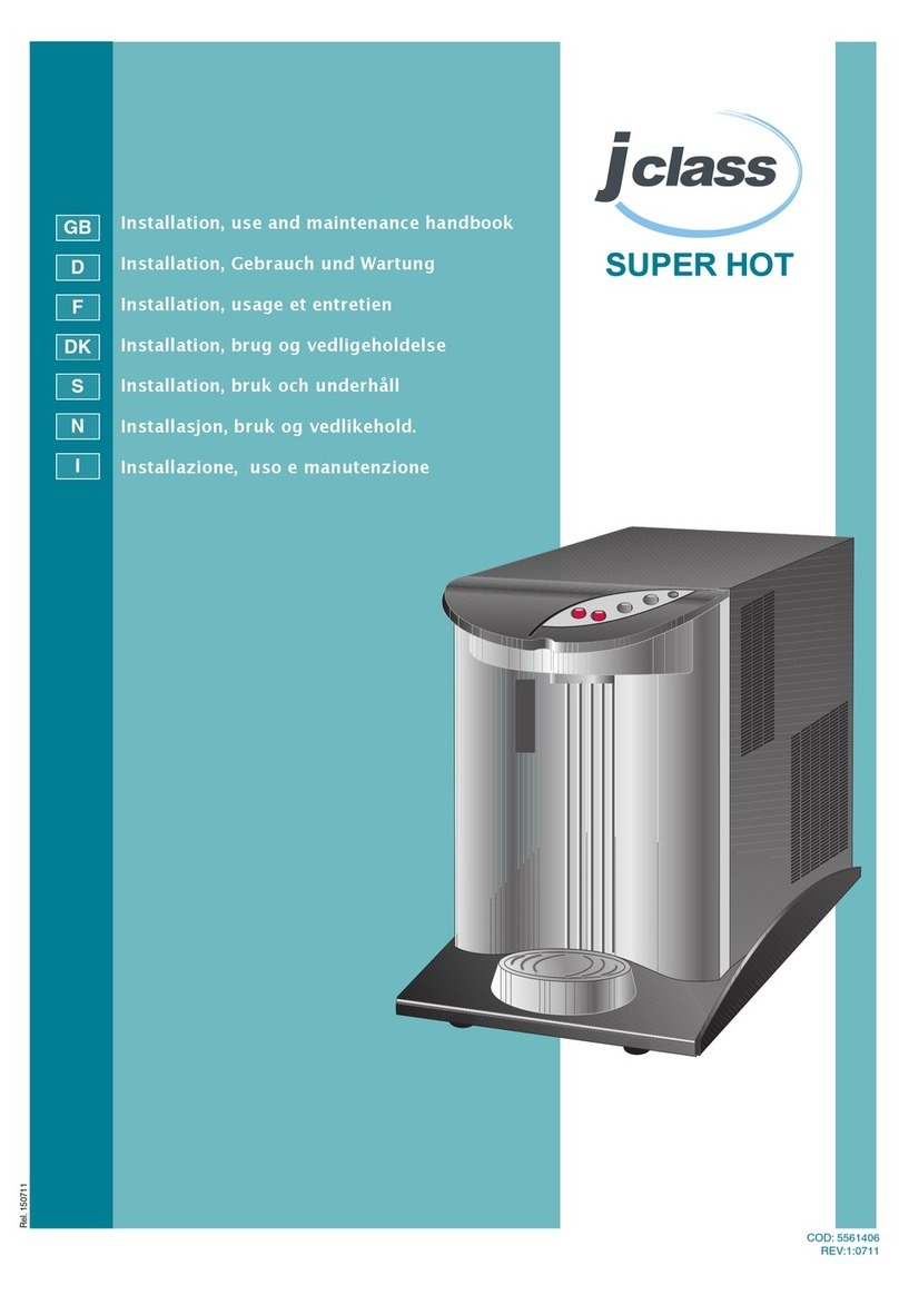
JCLASS SUPER HOT Installation, use and maintenance handbook

AFWFilters
AFWFilters 5600 Series installation instructions
Kenmore
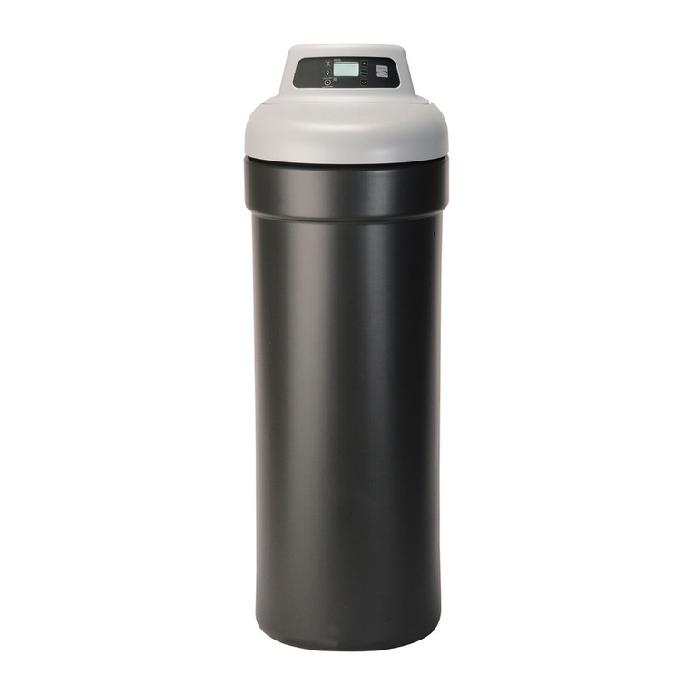
Kenmore 350 Series owner's manual
InSinkErator
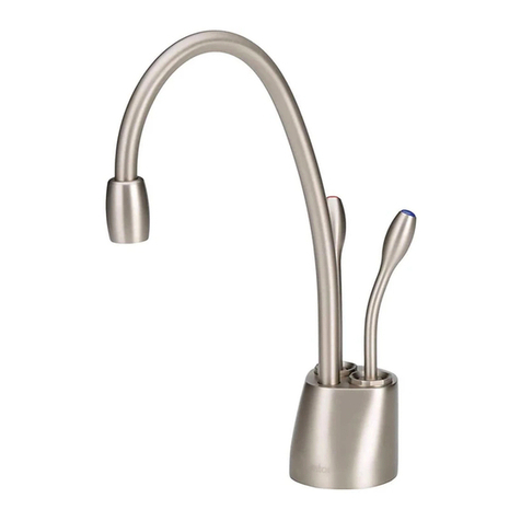
InSinkErator indulge Series owner's manual

Aqua Cooler
Aqua Cooler ODYSSEY Series Usage and Care Manual
BRIO
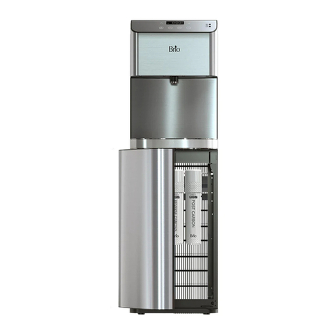
BRIO CLPOU720UVRO4X Setup manual
Morton
Morton MSS20B Installation and operation manual
