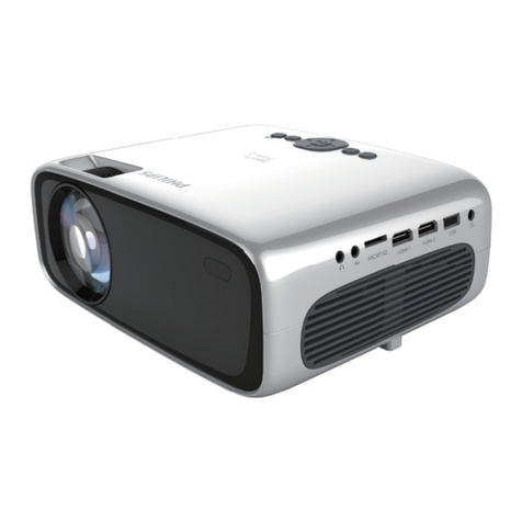
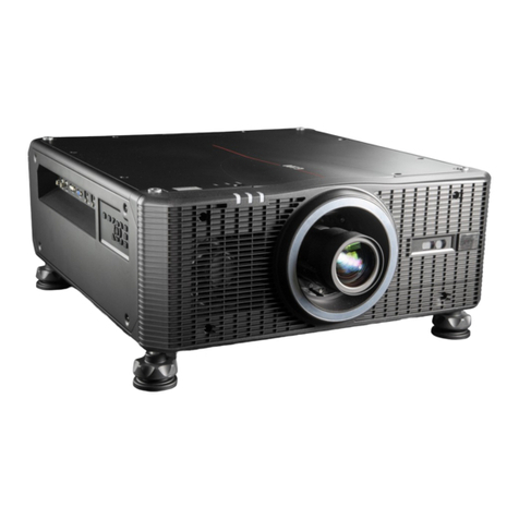
BOPIXEL OPR305 Series User manual

OPR305 Series DLP projector operating manual
Catalogue
一、Precautions for use .........................................................................................1
二、Module Hardware Features ................................................................................2
三、Connectors Description....................................................................................... 4
3.1 Connectors function .......................................................................................... 4
3.2 Pin function .......................................................................................................4
3.2.1 J1 ............................................................................................................. 4
3.2.2 J2 ............................................................................................................. 5
3.2.3 J3 ............................................................................................................. 5
3.2.4 J6 ............................................................................................................. 5
3.2.5 J7 ............................................................................................................. 6
3.2.6 J8 ............................................................................................................. 6
3.2.7 J9 ............................................................................................................. 6
3.2.8 J10 ........................................................................................................... 6
四、Operating Manual ................................................................................................7
4.1 Product description ........................................................................................... 7
4.2 software and documents ....................................................................................7
4.2.1 Software .................................................................................................. 7
4.2.2 Documents .............................................................................................. 7
4.3 software install .................................................................................................. 7
4.4 Operating instructions .......................................................................................9
4.4.1 drivers install ...........................................................................................9
4.4.2 connection of OPR305 series module .....................................................9
4.4.3 Lens adjustment and fixation .................................................................. 9
4.5 software Operating instructions ...................................................................... 10
4.5.1 pattern sets set up ..................................................................................10
4.5.2 add 1d pattern ........................................................................................11
4.5.3 pattern’s timing setting ..........................................................................12
4.5.4 pattern control ....................................................................................... 13
4.6 LED brightness adjustment .............................................................................14
4.6.1 LED switch ........................................................................................... 14
4.6.2 Light source current adjustment under 4A ........................................... 14
4.7 making batch file ............................................................................................ 17

4.8 Making firmware ............................................................................................ 22
五、Appendix .............................................................................................................26
5.1 DLP3010EVM-LC Firmware Release Notes ................................................. 26
5.2 "Internal Patterns" mode operation steps ........................................................27
5.3 How to Modify the Specifications of Test Patterns? ...................................... 33
六、FAQ ..................................................................................................................... 35
6.1 How to Program the DLPC3470 and DLPC3478? ......................................... 35
6.2 What is a 1D pattern? ......................................................................................35
6.3 Why would you want to use a 1D pattern? ..................................................... 36
6.4 What is a pattern set? ...................................................................................... 36
6.5 How many patterns can be stored in each pattern set? ................................... 36
6.6 How to change frame rate of internal pattern? ............................................... 37
6.7 Why is there a minimum pre-exposure dark time and post-exposure dark time
limit? ..................................................................................................................... 37
6.8 What actually happens in pre-exposure dark time and post-exposure dark time?
.............................................................................................................................. 37
6.9 What timings are supported by Internal pattern streaming mode? ................. 38
6.10 Do these minimum darkfield times have to be calculated?.......................... 38
七、Guarantee ........................................................................................................... 39

1
一、Precautions for use
Please read the manual thoroughly before use, misoperation may
cause damage to the DLP projector.
Attention
1. Optical module is fragile product, no dropping and disassembly is allowed.
2. Please power the optical module with 12V and higher than 4A power source.
3. Do not detach DMD FPC.
4. Please take anti-static measures before use
5. The optical module has only blue light source, do not enable red or green light
source.
6. Be aware of short circuit while wiring the optical module to other equipment.
7. This module will automatically power on when connected to power source.
Please contact us if not work properly.
8. Please read through the instructions before use. Misoperation may cause damage
to the module.
9. Please pay attention to anti-static measures before use. Static electricity will
cause damage to the main chip or DMD.
10. Before powering on, check whether there is overlap of the metal part of the IO
wire or foreign matter on the PCB board. The overlap of the bare IO wire or the
conductive foreign matter on the PCB board may cause a short circuit and cause
damage to the PCB board.
11. The power of the light source of this DLP projector is high.It is forbidden to
power on machine without connecting the radiator, the light source may burn out
within a few seconds.
Note: the GUI version used in this document is 2.2.0.6 and the operating system is
win10 x64.

2
二、Module Hardware Features
1. Resolution:1280x720
2. Max frame rate:2487Hz(1 bit),272Hz(8 bit)
3. Integrated 2M storage, store >1000 patterns in the flash memory.
4. Max power: 15W
5. Communication port:I2C(operation control),SPI(firmware programming),
USB(GUI connection)
6. Trigger voltage:5V default
7. 24-bit input pixel interface support: parallel or BT656, interface protocols.
8. Small dimension, a large aperture, optional Blue /RGB light source, extremely
high MTF and sharp image edges
9. Low distortion, distortion is less than 0.05%
10. Uniformity>90%,Facilitate the use of grayscale coding pattern
11. Users customize optical performance for specific requirements
OPR305 series (DLP3010)
Type OPR305100 OPR305120 OPR305185 OPR305120S OPR305185S
Working
distance
mm
MI
N
TY
P
MA
X
MI
N
TY
P
MA
X
MI
N
TY
P
MA
X
MI
N
TY
P
MA
X
MI
N
TY
P
MA
X
90 100 115 60 120 280 30 185 700 65 120 145 85 185 540
Screen size
(TYP)
mm
24.3*13.7 60.4*34 136*77 Picture 1 Picture 2
Depth of
focus
mm
-2~+2 -15~+19 -55~+100 -5~+10 -30~+40
Throw
Ratio 4.12 1.99 1.36 1.99 1.36
Precision
um 19 47 106 47 106
Mode Orthographic projector Scheimpflug/Tilt structure
Dimension
mm 92*57*36 99*57*36 104*57*36 100*78*41 103*72*41
Distortion <0.05% <0.1%
Resolution 1280*720
Uniformity
JBMA >90%
Contrast 1000:1
Light source Blue LED(459nm)

3
Figure 1. OPR305 series top Figure 2. OPR305 series side
Figure 3. OPR305 series Scheimpflug top Figure 4. OPR305 series Scheimpflug side
Figure 5. OPR305120S Figure 6. OPR305185S

4
三、Connectors Description
If you need to connect OPR305 series module to MCU, you need to detach the
protection plate and connect J6 to your system. After the connection you need to
reinstall the protection plate before powering up.
You can find the connector number in the figure upside, and the red dot stands
for pin 1 of the connector.
3.1 Connectors function
Number Mates with part number Function
J1 MOLEX 43645-0200 Power source port
J2 MOLEX 51021-0400 USB for embedded
J3 USB TYPE C USB type C port
J6 AXT650124 Extend function port
J7 MOLEX 51021-0300 Fan port
J8 MOLEX 87439-0400 Power output
J9 MOLEX 51021-0600 Trigger output
J10 MOLEX 51021-0300 Trigger input
3.2 Pin function
3.2.1 J1
Pin num. Pin name Function
1 SYSPWR Power source 12V
2 GND Power source GND

5
3.2.2 J2
Pin num. Pin name Function
1 GND USB GND
2 DP DP
3 DN DN
4 VBUS USB power
3.2.3 J3
Mate with common use USB TYPE C cable
3.2.4 J6
Pin
num.
Pin name Function Pin
num.
Pin name Function
25 GND 26 GND
24 PDATA0 Video input 27 TRIG1_IN Trigger in
23 PDATA1 28 TRIG1_OUT Trigger out 1
22 PDATA2 29 TRIG2_OUT Trigger out 2
21 PDATA3 30 MCU_REQ Hand shaking
REQ
20 PDATA4 31 HOST_IRQ DLP state
19 PDATA5 32 RESETZ
18 PDATA6 33 MCU_ACK Hand shaking
ACK
17 PDATA7 34 PROJ_ON Power up signal
16 GND 35 PATTERN_READY Ready to
project
15 PDATA8 Video input 36 SPI0_CSZ0 SPI
14 PDATA9 37 SPI0_MISO
13 PDATA10 38 SPI0_MOSI
12 PDATA11 39 SPI0_CLK
11 PDATA12 40 I2C0_SDA I2C
10 PDATA13 41 I2C0_SCL
9 PDATA14 42 GND
8 PDATA15 43 PDM_CVS_TE Video input
7 GND 44 HSYNC_CS
6 PDATA16 Video input 45 VSYNC_WE
5 PDATA17 46 DATEN_CMD
4 PDATA18 47 PCLK
3 PDATA19 48 GND
2 PDATA20 49 PDATA23 Video input
1 PDATA21 50 PDATA22

6
3.2.5 J7
Pin num. Pin name Function
1 Fan power Fan power 12V
2 Fan lock detect Not used
3 GND Fan power GND
3.2.6 J8
Pin num. Pin name Function
1 3.3V output 3.3V 2A power out
2 5.0V output 5.0V 2A power out
3 12.0V output 12V 2A power out
4 GND Power GND
3.2.7 J9
Pin num. Pin name Function
1 Triger1 out VCC Trigger out voltage VCC
2 Triger1 output Trigger1 output
3 GND Trigger GND
4 Triger2 out VCC Trigger out voltage VCC
5 Triger2 output Trigger2 output
6 GND Trigger GND
3.2.8 J10
Pin num. Pin name Function
1 Triger1 in VCC Trigger in voltage VCC
2 Triger1 input Triger1 input
3 GND Trigger GND

7
四、Operating Manual
4.1 Product description
OPR305 series module are made for structured light projection, they can project
several 2D build in test patterns and programmable 1D 1bit or 8bit patterns.
Attention: OPR305 series module are different from TI DLP3010EVM-LC,
some functions of TI GUI will not be supported. The firmware of DLP3010EVM-LC
can not work on our system. Please use the firmwares from our website.
4.2 software and documents
4.2.1 Software
GUI:https://www.ti.com/tool/cn/DLPDLC-GUI
Firmware:
cus_5a_out12_in_run.img
cus_5a_out12_AutoRun.img
API:DLPC34XX-API
4.2.2 Documents
OPR305 系列 DLP 模块使用说明(本文档)
DLP Display and Light Control EVM GUI Tool User Guide (Rev. A)
DLP3010LC 0.3 720p 光控 DMD 数据表
DLPA3000 驱动器
DLPC34xx Controller API User's Guide
DLPC3470 and DLPC3478 Software Programmer's Guide
DLP3010 曝光时间参考表
4.3 software install
GUI install

8
图1
图2
图3
图4图5
图6
图7

9
Please use DLP3010LC with OPR305 series module.
4.4 Operating instructions
4.4.1 drivers install
Once first attached OPR305 series module to PC, some drivers will
automatically installed on your PC.
4.4.2 connection of OPR305 series module
Use a USB A to USB typeC cable connect OPR305 series module to PC, connect
the module to 12V power source, and then open DLP3010LC.exe . If the connection
is correct, you will see EVM Status;Test Pattern Generator on the lower left side of
GUI window. Click once one more on the green button will disconnect the module.
Click on the “get” button will get some information of the module.
4.4.3 Lens adjustment and fixation
As the figure below, there two objects on the lens can be adjusted. Focusing
knob and locking screw. Adjusting the focusing knob to make the screen more clearly,
and then lock up the locking screw to fix the lens.
图8

10
4.5 software Operating instructions
OPR305 series module are made for high speed structure light projection, in this
case, the patterns will preinstalled into flash onboard, and operating in “internal
patterns” mode.
4.5.1 pattern sets set up
Patterns sets are set up for putting several similar patterns into one place, and
then they could use one parameter setting.
The max patterns number can be placed in one pattern set is listing below:
1D Pattern Type Max # of Patterns
8-bits vertical patterns 6
8-bits horizontal patterns 8
1-bits vertical patterns 51
1-bits horizontal patterns 64
Click “light control” tab
Click “internal patterns”
On the the Pattern Sets page, user can add or delete pattern sets and add or delete
patterns to and from each pattern set. Apreview window on the right shows the pattern
selected. Click Next on the bottom-right or any of the tab (Pattern Order or Pattern
Control) on the left to continue.

11
4.5.2 add 1d pattern
Tips:1d pattern stands for patterns that have grayscale varies only in one
direction.
GUI supports only PNG and BMP format.
The resolution of DLP3010 is 1280 x 720, user should add pattern just one pixel line.
For horizontal pattern sets, please add 1 x 720 pattern.
For vertical pattern sets, please add 1280 x 1 pattern.
If patterns added correctly, you will see pattern showed on the right side. User can
only add 1bit or 8bit pattern in pattern sets. 24bit colour pattern is not supported.

12
4.5.3 pattern’s timing setting
OPR305 series have only blue light source, in illumination setting, user can only
set to B.
Exposure time stands for module projecting time, pre-exposure dark time and
pose-exposure dark time are set for module to prepare, they can not be too short. If the
timing user sets are not supported, a window will show up to tell user which part need
to change when user click the “Program and load” button.
You will see more information in 《DLP3010EVM-LC Firmware Release Notes》
After timing setting, click “Program and load” button to program all the patterns
into flash.

13
4.5.4 pattern control
On the Pattern Control page, users can configure the trigger out, trigger in and
pattern ready signals and to control the display of patterns in internal pattern mode.
This page requires the EVM to be connected to the GUI in order to work.
Configure the triggers and pattern ready signal as required and click Set. To view
the current configuration of these signals, click Get. After all the configurations are
set, the user can select and control how to run these patterns:
run once, run continuously, pause, step, stop, reset
In trigger in mode, module project only one pattern when receive one trigger
signal.
The configuration take effect after click “set” button, but will lost after
disconnect the power source. If user wish to storage the configuration, could make a
batch file, and program it into a firmware, and then write it in flash.

14
4.6 LED brightness adjustment
4.6.1 LED switch
On display tab intellibright page, user could enable blue LED and adjust the
brightness of light source. Check enable and press set button to turn on the light
source. Move the current block and then press set button to set a new brightness.
Attention: user can not enable red LED and green LED.
4.6.2 Light source current adjustment under 4A
OPR305 series module have the max light source current of 5A. It is much
higher then the GUI presented. GUI programmed for TI DLP3010EVM-LC, the
current on GUI is not the same on our module.
In DLP system, there is a 10bit register storage the brightness message. It can be
adjusted from 0 to 1023. 0 stands for 0A, and 1023 stands for 6A on our module.
When operating OPR305 series module, user should not configure the current more
than 5A(850). In this GUI, when user move the block to the right side, and current
said 2500mA, in fact the number written into register is 700 about 4.2A on OPR305
module. The brightness is much higher than DLP3010EVM-LC, but still not the max
brightness of out module, to reach 5A (850) current, user could set it in advanced
mode.

15
①Connect OPR305 series module to PC with USB type C cable, and power up
the module. If connection is correct, user can click advanced button to get into
advanced mode.
②Click connection button to connect module in advanced mode.

16
③In illumination tab, there is a rgb led current window. Press get button to get
current number of the light source.
④Check “blue led enable” and type in a number between 0 to 850 and then
press set button to set a new brightness.
User can not check “red led enable” and ”green led enable”.

17
After user press “set” button, the new number will written into module, then
press “get” button will get the new number.
4.7 making batch file
Batch file is used for storage custom configurations into flash, so user could not
set the same configurations every time after powering up the module.
The way to make batch file will be show below, the batch file users make can not
be used directly, please contact Bopixel’s engineer to help you finish the batch file, so
you can compile it into your firmware.
①Connect OPR305 series module to PC with USB type C cable, and power up
the module. And press advanced button, to start the advanced mode.

18
②After starting the advanced mode, it will automatically connect to module.
③Click “batch command” on the left side, you will see all the commands are
listing below.
This manual suits for next models
5
Table of contents
Other BOPIXEL Projector manuals
