Bosch Sensortec BNO055 User manual
Application Note
BNO055
Quick start guide
Bos ch Sensortec
Application note: BNO055 Quick start guide
Document revision 1.0
Document release date Mar.2015
Document number BS T-BNO055-AN007-00
Technical reference code 0 273 141 209
Notes
Data in this document are subject to change without notice.
P
roduct photos and pictures are for illustration purposes only and
m
ay differ from the real product’s appearance.

Application Note
BNO055 - Quick start guide
Page 2
BST-BNO055 -AN 00 7 -00| Versi on 1. 0 | Ma r ch 2015
Bosch Sensortec
© Bosch Sensort ec G mbH reserves all ri gh t s even in the event of i ndustrial property rig ht s. We reserv e all ri gh t s of di sposal such as copying and passing on to third
parti es. BOSCH and the sym bol are regi st ered trademarks of Robert Bosch GmbH, Germany.
Note: Speci fi cati on s wi thin thi s d ocu m ent are subj ect tochange wi t h out noti ce.
Contents
1. Introduction..........................................................................................................................3
2. Hardware design..................................................................................................................5
2.1 Schematics ......................................................................................................................5
3. Calibration ............................................................................................................................6
4. Sample codes ......................................................................................................................7
5Legal disclaimer.................................................................................................................8
5.1 Engineering samples .......................................................................................................8
5.2 Product use.....................................................................................................................8
5.3 Application examples and hints........................................................................................8

Application Note
BNO055 - Quick start guide
Page 3
BST-BNO055 -AN 00 7 -00| Versi on 1. 0 | Ma r ch 2015
Bosch Sensortec
© Bosch Sensort ec G mbH reserves all ri gh t s even in the event of i ndustrial property rig ht s. We reserv e all ri gh t s of di sposal such as copying and passing on to third
parti es. BOSCH and the sym bol are regi st ered trademarks of Robert Bosch GmbH, Germany.
Note: Speci fi cati on s wi thin thi s d ocu m ent are subj ect tochange wi t h out noti ce.
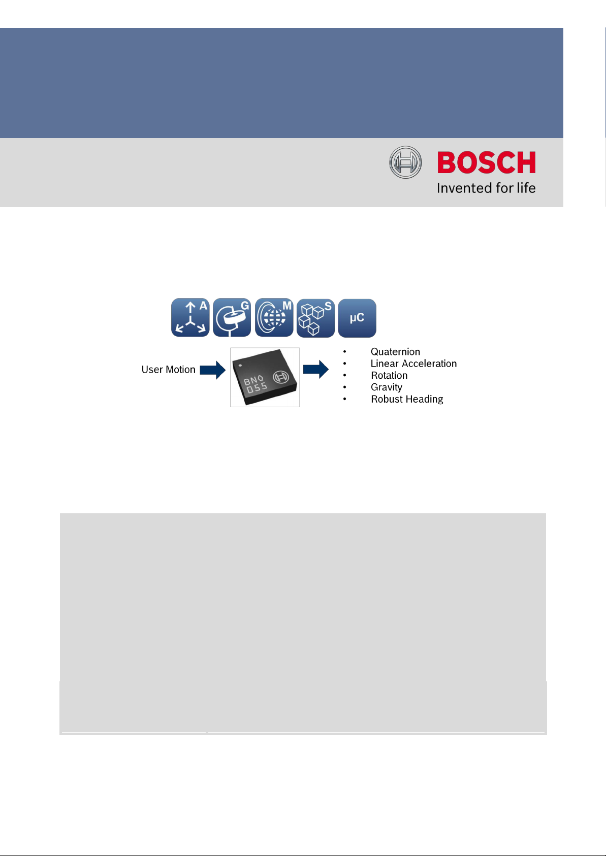
1. Introduction
The BNO055 is a system in package (SiP) chip that includes a 3-axis 14-bit accelerometer,
a 3-axis 16-bit gyr oscope, a 3-axis magnetometer and a 32-bit Cortex M0+ microcontroller
running the company’s BSX3.0 FusionLib software.
Besides giving access to the individual sensor signals such as acceleration, rotation,
and magnetic field strength, the sensor offers a total of five different sensor fusion modes. The
table below provides a quick overvie w of all the different fusion and non-fusion modes of the
sensor:
Operating Mode
Available sensor signals Fusion Data
Accel Mag Gyro
Relative
orientation
Absolute
orientation
CO NFI GM ODE
-
-
-
-
-
Non-fusionmodes
ACCONLY
X
-
-
-
-
MAGONLY
-
X
-
-
-
GYROONLY
-
-
X
-
-
ACCMAG
X
X
-
-
-
ACCGYRO
X
-
X
-
-
MAGGYRO
-
X
X
-
-
AMG X X X - -
Fusion modes
IMU
X
-
X
X
-
CO MP AS S
X
X
-
-
X
M4G
X
X
X*
X
-
NDOF_FMC_OFF
X
X
X
-
X
NDOF
X
X
X
-
X
* software simulated gyro signal
Fusion Modes:
IMU or Inertial Measurement Unit is a fusion of the accelerometer and the gyr oscope
Compass is a fusion of the accelerometer and magnetometer, also commonly known as a
tilt-compensated compass
M4G (Magnet for gyroscope) is a fusion of the accelerometer and the magnetometer but the
output data is similar to the IMU mode and hence the limitations of gyroscope is compensated
in this mode.
NDOF_FMC_OFF is a fusion of all three sensors – accelerometer, gyr oscope and the
magnetometer thereb y providing Nine Degrees of Freedom (NDOF). In this mode the ‘FMC
(Fast Magnetic Calibration)’ feature is disabled and thereb y the sensor needs a movement
similar to ‘figure 8 pattern’ to calibrate the magnetometer.
NDOF is also a fusion of all the three sensors, but with the feature ‘FMC’ enabled. By
enabling this feature, a quick movement (even an incomplete ‘figure 8 pattern’) will fully
calibrate the magnetometer.

Application Note
BNO055 - Quick start guide
Page 4
BST-BNO055 -AN 00 7 -00| Versi on 1. 0 | Ma r ch 2015
Bosch Sensortec
© Bosch Sensort ec G mbH reserves all ri gh t s even in the event of i ndustrial property rig ht s. We reserv e all ri gh t s of di sposal such as copying and passing on to third
parti es. BOSCH and the sym bol are regi st ered trademarks of Robert Bosch GmbH, Germany.
Note: Speci fi cati on s wi thin thi s d ocu m ent are subj ect tochange wi t h out noti ce.
Once the sensor is powered, it executes a power on self-test (POST) and stays in the
configuration (CONFIG) mode. After POR or soft reset, users need to wait at least 650ms
before talking to BNO055 through I2C interface. For the waiting time less than 650 ms, the I2C
communication does not respond. The hardware reset using h ardware RESET pin or writing to
the RST_SYS bit in the SYS_TRIGGER register (0x3F) have the same effect as the power on
rest (POR). Users can then change to one of the sensor operation modes by writing to the
OPR_MODE register (0x3D). Once the sensor is configured, it is ready to send the sensor
fusion results such as Quaternion, Euler angles, Linear acceleration and Gravity vector at
fixed output data rate. Users can then access the sensor fusion results from the BNO055
through I2C, UART or HID-over I2C interface.
The user can switch between Windows or the Android orientation format. By default however,
the sensor axes orientation of the sensor is of Android format as shown in Figure 1. The
Android rotation vector definition can be found at
http://developer.android.com/guide/topics/sensors/sensors_motion.html
Figure 1 BNO055 coordinate definition
•
Heading: rotation around the Z axis (0° <= heading < 360°). 0° = North, 90° = East,
180° = South, 270° = West. The heading value increases when you rotate around the Z
axis clo ckwise from top view of Figure 1.Pitch: rotation around the X axis (-180° <= pitch
<= 180°) with positive values increasing when the Z axis moves towards the Y axis.
•
Roll: rotation around the Y axis (-90° <= roll <= 90°) with positive values increasing when
the X
axis mo ves toward the Z axi s .
East
North

Application Note
BNO055 - Quick start guide
Page 5
BST-BNO055 -AN 00 7 -00| Versi on 1. 0 | Ma r ch 2015
Bosch Sensortec
© Bosch Sensort ec G mbH reserves all ri gh t s even in the event of i ndustrial property rig ht s. We reserv e all ri gh t s of di sposal such as copying and passing on to third
parti es. BOSCH and the sym bol are regi st ered trademarks of Robert Bosch GmbH, Germany.
Note: Speci fi cati on s wi thin thi s d ocu m ent are subj ect tochange wi t h out noti ce.
2. Hardware design
2.1 Schematics
BNO055 schematic is as shown in figure 2 with I2C interface to an external microcontroller
(MCU)1.
MCU
Figure 2 BNO055 schematics with I2C interface
Notes:
•
The external 32.768 kHz crystal is optional. Pin-26 (XOUT32) and Pin-27 (XIN32) can be
floating when the external crystal is not used.
•
Pin-5 (PS1) and Pin-6 (PS0) should be tied to GND directly o r through a zero Ohm resistor to
GND to select I2C interface protocol. Don’t use a pull-down resistor for these two pins.
•
The MCU GPIO1 can be used to select the BNO055 7-bit I2C slave address, which will be
0x29 when GPIO1 is high and 0x2 8 when low.
•
Pin-14 (INT) is push-pull and can be tied to MCU GPIO2 directly. This pin can be floating if
BNO055 interrupt is not used.
•
Pin-4 (nBOOT_LOAD_PIN) is pulled high through a 10K Ohms resistor. It is not necessary
to tie it to the other MCU GPIO pin.
1 Since majority of the application use I2C, the quick reference guide explains thi s commu nication protocol more in
detail.
VDD
S DA
SCL
GPIO1
GPIO2
Application Note
BNO055 - Quick start guide
Page 6
BST-BNO055 -AN 00 7 -00| Versi on 1. 0 | Ma r ch 2015
Bosch Sensortec
© Bosch Sensort ec G mbH reserves all ri gh t s even in the event of i ndustrial property rig ht s. We reserv e all ri gh t s of di sposal such as copying and passing on to third
parti es. BOSCH and the sym bol are regi st ered trademarks of Robert Bosch GmbH, Germany.
Note: Speci fi cati on s wi thin thi s d ocu m ent are subj ect tochange wi t h out noti ce.
3. Calibration
Calibration of the sensor plays a major role in the sensor fusion software. In the BNO055, the
calibration of the accelerometer, gyr oscope and the magnetometer runs in the background as
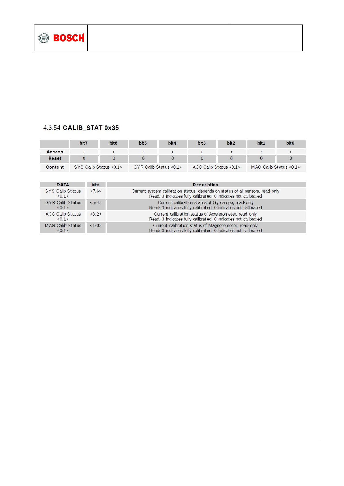
part of the sensor fusion software. The status of each sensor calibration is as shown in Figure 4.
Figure 4: BNO055 sensor calibration status register
The accelerometer and the gyr oscope are relative ly less susceptible to external disturbances,
as a result of which the offset is negligible. Moreover the accelerometer is factory
calibrated, and hence the calibration is not mandatory. For the gyr oscope however leaving the
BNO055 stationary for a few seconds at any time during the operation, will facilitate full
calibration and thereby remove the zero rate offsets. Unlike the accelerometer and
gyr oscope, the magnetometer calibration is mandatory immediately after e ve r y ‘power on reset’
in order for sensor fusion to create accurate results.
Therefore, it is highly recommended to check the magnetometer calibration status periodically.
If the value of the two bits ‘MAG Calib Status’ is 3, then it means that the magnetometer is fully
calibrated and readyto go . If the value is 2, then the sensor fusion’s performance is still OK. If
the value is 1, then it is highly recommended to perform a Figure-8 motion to calibrate the
magnetometer. And if the value is 0, this means that the magnetometer just got disturbed by
the magnetic interference fields nearb y or the environment’s magnetic fields have just
changed. And therefore the magnetometer calibration must be performed. For further details
please refer section ‘3.10 Calibration’ in the datasheet.

Application Note
BNO055 - Quick start guide
Page 7
BST-BNO055 -AN 00 7 -00| Versi on 1. 0 | Ma r ch 2015
Bosch Sensortec
© Bosch Sensort ec G mbH reserves all ri gh t s even in the event of i ndustrial property rig ht s. We reserv e all ri gh t s of di sposal such as copying and passing on to third
parti es. BOSCH and the sym bol are regi st ered trademarks of Robert Bosch GmbH, Germany.
Note: Speci fi cati on s wi thin thi s d ocu m ent are subj ect tochange wi t h out noti ce.
4. Sample codes
It is highly recommended to use the BNO055 standard APIs to ease the integration. The APIs
can be downloaded from https://github.com/BoschSensortec/BNO055_driver.
Below mentioned steps demonstrate how to get BNO055 up and running with few API calls.
Step
D e s c r ip t ion
Code snippet
1
Power on the BNO055
2
Create a structure to hold
device information
struct bno055_t myBNO;
3
Link the I2C driver functions
to the API communication
function pointer
myBNO.bus_read = BNO055_I2C_bus_read;
myBNO.bus_write = BNO055_I2C_bus_write;
myBNO.delay_msec = delay;
4
Set the correct I2C address
in the BNO055 API
myBNO.dev_addr = BNO055_I2C_ADDR1;
//myBNO.dev_addr = BNO055_I2C_ADDR2;
5
API initialization
bno055_init(&myBNO);
6
Change the operation
mode to NDOF
bno055_set_operation_mode
(OPERATION_MODE_NDOF);
7
Read Euler angles
struct bno055_euler_float_t eulerData;
bno055_convert_float_euler_hpr_deg(&eulerDa
ta);
8
Read calibration status
unsigned char accel_calib_status = 0;
unsigned char gyro_calib_status = 0;
unsigned char mag_calib_status = 0;
unsigned char sys_calib_status = 0;
bno055_get_accel_calib_stat(&accel_calib_st
atus);
bno055_get_mag_calib_stat(&mag_
calib_status);
bno055_get_gyro_calib_stat(&gyro_
calib_status);
bno055_get_sys_calib_stat(&sys_
calib_status);
Note: It is advisable to check the calibration status periodically and provide accuracy status to the user
for re-calibration.

Application Note
BNO055 - Quick start guide
Page 8
BST-BNO055 -AN 00 7 -00| Versi on 1. 0 | Ma r ch 2015
Bosch Sensortec
© Bosch Sensort ec G mbH reserves all ri gh t s even in the event of i ndustrial property rig ht s. We reserv e all ri gh t s of di sposal such as copying and passing on to third
parti es. BOSCH and the sym bol are regi st ered trademarks of Robert Bosch GmbH, Germany.
Note: Speci fi cati on s wi thin thi s d ocu m ent are subj ect tochange wi t h out noti ce.
5 Legal disclaimer
5.1 Engineering samples
Engineering Samples are marked with an asterisk (*) or (e). Samples may vary from the
valid technical specifications of the product series contained in this data sheet. They are
therefore not intended or fit for resale to third parties or for use in end products. Their sole
purpose is internal client testing. The testing of an engineering sample may in no way
replace the testing of a product series. Bosch Sensortec assumes no liability for the use of
engineering samples. The Purchaser shall indemnify Bosch Sensortec from all claims arising
from the use of engineering samples.
5.2 Product use
Bosch Sensortec products are developed for the consumer goods industry. They may only be
used within the parameters of this product data sheet. They are not fit for use in life-sustaining or
security sensitive s ys tems. Security sensitive s ys tems are those for which a malfunction is
expected to lead to bodily harm or significant property damage. In addition, they are not fit for
use in products which interact with motor vehicle s ys tems.
The resale and/or use of products are at the purchaser’s own risk and his own responsibility. The
examination of fitness for the intended use is the sole responsibility of the Purchaser.
The purchaser shall indemnify Bosch Sensortec from all third party claims arising from an y
product use not covered by the parameters of this product data sheet or not approved by Bosch
Sensortec and reimburse Bosch Sensortec for all costs in connection with such claims.
The purchaser must monitor the market for the purchased products, particularl y with regard to
product safety, and inform Bosch Sensortec without delay of all security rele van t incidents.
5.3 Application examples and hints
With respect to any examples or hints given herein, any typical values stated herein and/or any
information regarding the application of the device, Bosch Sensortec hereby disclaims any and
all warranties and liabilities of any kind, including without limitation warranties of non-infringement
of intellectual property rights or copyrights of any third party. The information given in this
document shall in no event be regarded as a guarantee of conditions or characteristics. They are
provided for illustrative purposes only and no evaluation regarding infringement of intellectual
property rights or copyrights or regarding functionality, performance or error has been made.

Application Note
BNO055 - Quick start guide
Page 9
BST-BNO055 -AN 00 7 -00| Versi on 1. 0 | Ma r ch 2015
Bosch Sensortec
© Bosch Sensort ec G mbH reserves all ri gh t s even in the event of i ndustrial property rig ht s. We reserv e all ri gh t s of di sposal such as copying and passing on to third
parti es. BOSCH and the sym bol are regi st ered trademarks of Robert Bosch GmbH, Germany.
Note: Speci fi cati on s wi thin thi s d ocu m ent are subj ect tochange wi t h out noti ce.
6 Document history and modification
Re v. No
Chapter
Description of modification/change s
Date
1.0
Document creation 04 March 2015
Bosch Sensortec GmbH
Gerhard- Kindler-Strasse 8
72770 Reutlingen/
Ge rm a ny
conta ct @bosch-sensortec.com
www.bosch-sensortec. com
Modifications reserved | Printed in G ermany
Specifications subject to cha nge without not ice
Document number: BST- BNO055-AN007- 00
Ve rsi o n _ 1. 0 _ 050315
Table of contents


