juncLio_ box and
hree prong plu
are included
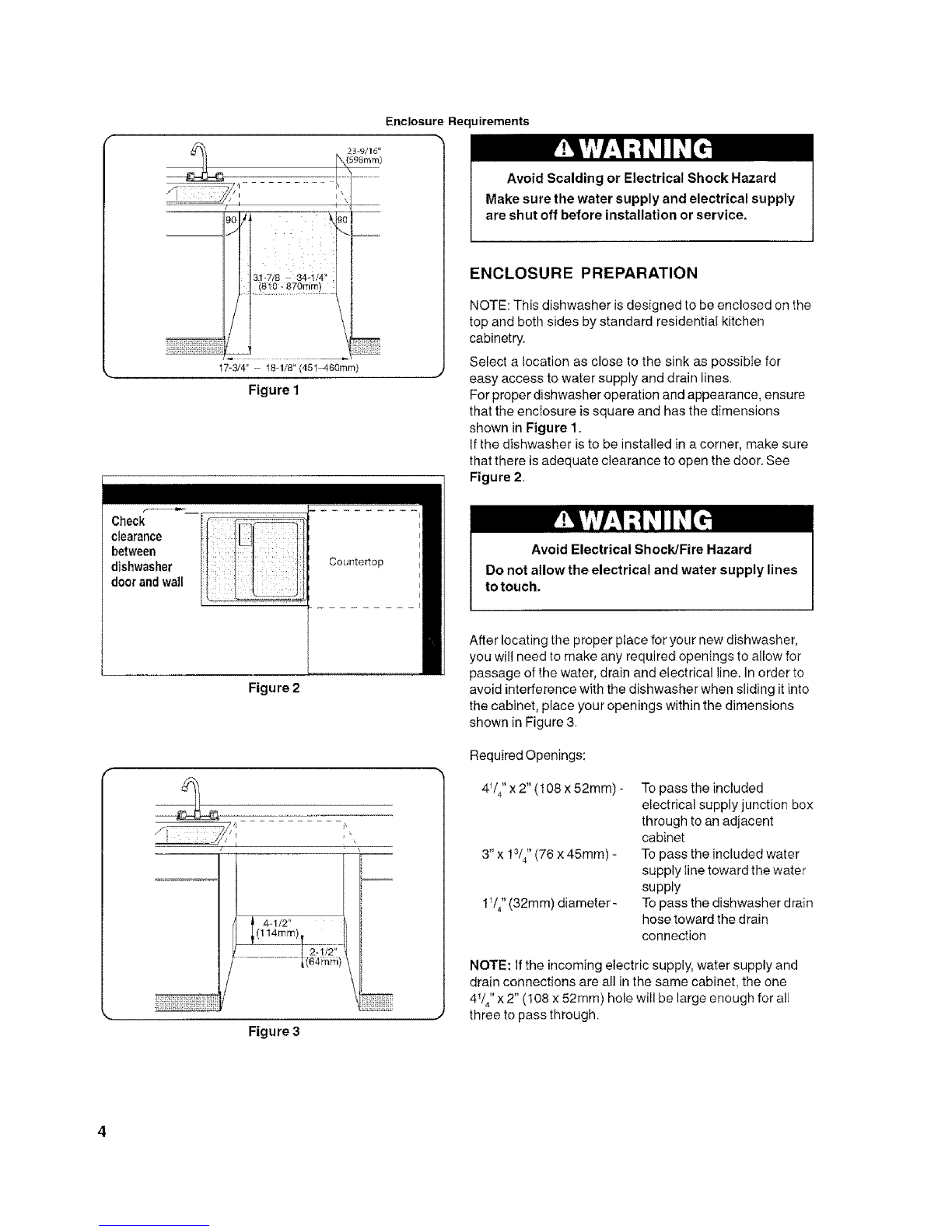
Figure 4
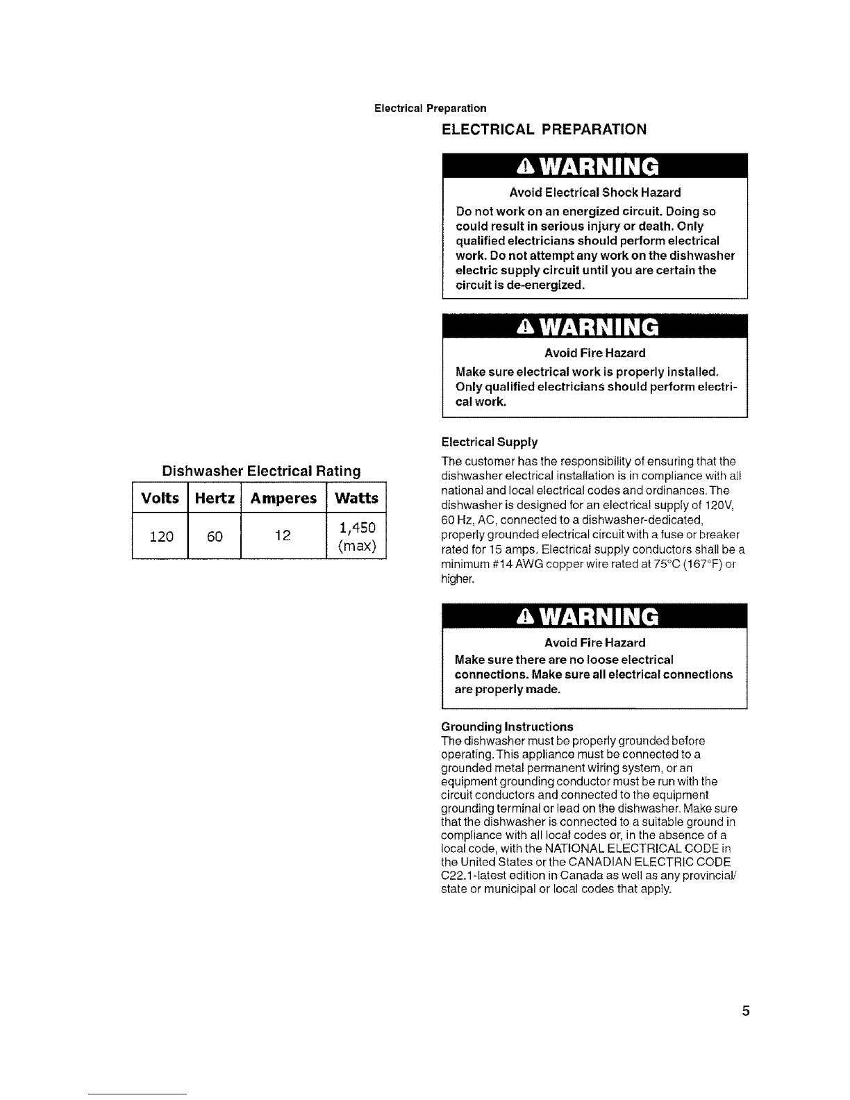
(51mm - 76mm).
3/8"- 1/2"
(lOmm - 13mm)
Figure 5
r
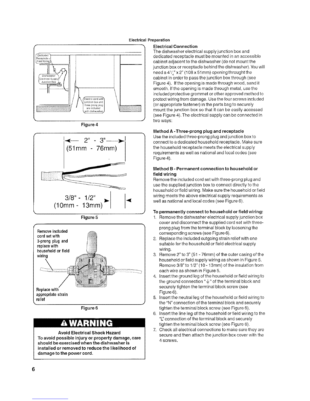
Removeincluded
cord setwith
3-prong plug and
replace with
household or field
wiring
Replace
appropriate strain
relief
Figure 6
Avoid Electrical Shock Hazard
To avoid possible injury or property damage, care
should be exercised when the dishwasher is
installed or removed to reduce the likelihood of
damage to the power cord.
Electrical Preparation
Electrical Connection
The dishwasher electrical suppIy junction box and
dedicated receptacle must be mounted in an accessible
cabinet adjacent to the dishwasher (do not mount the
junction box or receptacle behind the dishwasher). You will
need a 4I/4'' x 2" (108 x 51mm) opening throught the
cabinet in order to pass the junction box through (see
Figure 4). tfthe opening is made through wood, sand it
smooth_ If the opening is made through metal, use the
included protective grommet or other approved method to
protect wiring from damage. Use the four screws included
(or appropriate fastener) in the parts bag to secureIy
mount the junction box so that it can be easily accessed
(see Figure 4).The electrical supply can be connected in
......-" two ways:
Method A -Three-prong plug and receptacle
Use the included three-prong plug and junction box to
connect to a dedicated household receptacle. Make sure
the household receptacle meets the electrical suppIy
requirements as well as national and local codes (see
Figure 4).
Method B -Permanent connection to household or
field wiring
Remove the included cord set with three-prong plug and
use the supplied junction box to connect directly to the
household or field wiring. Make sure the househoId or field
wiring meets the above electrical supply requirements as
well as national and local codes (see Figure 6).
To permanently connect to household or field wiring:
1. Remove the dishwasher electrical supply junction box
cover and disconnect the supplied cord set with three-
prong plug from the terminal block by loosening the
corresponding screws (see Figure 6).
2. Replace the included outgoing strain relief with one
suitable for the household or field electrical supply
wiring,
3, Remove 2" to 3" (51 - 76ram) of the outer casing of the
household or field supply wiring as shown in Figure 5.
Remove 3/8" to 1/2" (10 - 13mm) of the insulation from
each wire as shown in Figure 5.
4, Insert the ground leg of the household or field wiring to
the ground connection "€" of the terminal block and
securely tigt_ten the terminal block screw (see
Figure 6).
5. Insert the neutral leg of the household or field wiring to
the "N" connection of the terminal block and securely
tighten the terminal block screw (see Figure 6}.
6. Insert the line leg of the household or field wiring to the
"L_'connection of the terminal block and securely
tighten the terminal block screw (see Figure 6).
7. Check all electrical connections to make sure they are
secure and then attach the junction box cover with the
4 screws.
6