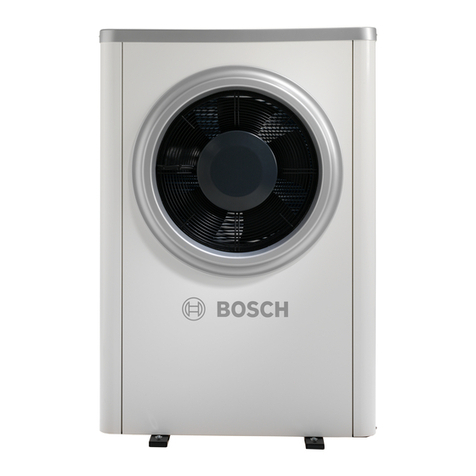
Table of contents
AWE – 6721835317 (2021/09)
2
Table of contents
1 Explanation of symbols and safety instructions . . . . . . . . . . . 3
1.1 Explanation of symbols . . . . . . . . . . . . . . . . . . . . . . . . . . 3
1.2 General safety instructions . . . . . . . . . . . . . . . . . . . . . . . 3
2 Regulations . . . . . . . . . . . . . . . . . . . . . . . . . . . . . . . . . . . . . . . . . . 3
2.1 Water quality . . . . . . . . . . . . . . . . . . . . . . . . . . . . . . . . . . 4
3 Product description . . . . . . . . . . . . . . . . . . . . . . . . . . . . . . . . . . . 5
3.1 Supplied parts . . . . . . . . . . . . . . . . . . . . . . . . . . . . . . . . . 5
3.2 Information on the indoor unit. . . . . . . . . . . . . . . . . . . . . 5
3.3 Declaration of conformity . . . . . . . . . . . . . . . . . . . . . . . . 5
3.4 Type plate . . . . . . . . . . . . . . . . . . . . . . . . . . . . . . . . . . . . . 6
3.5 Product overview . . . . . . . . . . . . . . . . . . . . . . . . . . . . . . . 6
3.6 Product dimensions and minimum clearances. . . . . . . . 6
4 Preparing for installation . . . . . . . . . . . . . . . . . . . . . . . . . . . . . . 7
4.1 Assembly of the indoor unit. . . . . . . . . . . . . . . . . . . . . . . 7
4.2 Minimum volume and execution of the heating
system. . . . . . . . . . . . . . . . . . . . . . . . . . . . . . . . . . . . . . . . 7
5 Installation . . . . . . . . . . . . . . . . . . . . . . . . . . . . . . . . . . . . . . . . . . 8
5.1 Transport and storage . . . . . . . . . . . . . . . . . . . . . . . . . . . 8
5.2 Unpacking. . . . . . . . . . . . . . . . . . . . . . . . . . . . . . . . . . . . . 8
5.3 Checklist. . . . . . . . . . . . . . . . . . . . . . . . . . . . . . . . . . . . . . 8
5.4 Connection . . . . . . . . . . . . . . . . . . . . . . . . . . . . . . . . . . . . 9
5.4.1 Connecting the indoor unit to the heat pump and
the heating system. . . . . . . . . . . . . . . . . . . . . . . . . . . . . . 9
5.4.2 Outdoor unit, indoor unit and heating system
filling . . . . . . . . . . . . . . . . . . . . . . . . . . . . . . . . . . . . . . . . 10
5.4.3 Heating circuit pump (PC1). . . . . . . . . . . . . . . . . . . . . . 11
5.4.4 Electrical connection . . . . . . . . . . . . . . . . . . . . . . . . . . . 11
6 Commissioning. . . . . . . . . . . . . . . . . . . . . . . . . . . . . . . . . . . . . . 16
6.1 Venting the outdoor unit, indoor unit and heating
system. . . . . . . . . . . . . . . . . . . . . . . . . . . . . . . . . . . . . . . 16
6.2 Adjusting the operating pressure of the heating
system. . . . . . . . . . . . . . . . . . . . . . . . . . . . . . . . . . . . . . . 17
6.3 Operation without heat pump (individual
operation). . . . . . . . . . . . . . . . . . . . . . . . . . . . . . . . . . . . 17
6.4 Function test. . . . . . . . . . . . . . . . . . . . . . . . . . . . . . . . . . 17
6.4.1 Pressure switch and overheating protection . . . . . . . . 17
6.4.2 Operating temperatures . . . . . . . . . . . . . . . . . . . . . . . . 17
7 Operation . . . . . . . . . . . . . . . . . . . . . . . . . . . . . . . . . . . . . . . . . . 18
8 Maintenance . . . . . . . . . . . . . . . . . . . . . . . . . . . . . . . . . . . . . . . . 18
8.1 Particle filter. . . . . . . . . . . . . . . . . . . . . . . . . . . . . . . . . . 18
8.2 Replacing components . . . . . . . . . . . . . . . . . . . . . . . . . 18
9 Installation of accessories . . . . . . . . . . . . . . . . . . . . . . . . . . . . 19
9.1 EMS-BUS for accessories . . . . . . . . . . . . . . . . . . . . . . . 19
9.2 External connections . . . . . . . . . . . . . . . . . . . . . . . . . . . 19
9.3 Maximum sensor . . . . . . . . . . . . . . . . . . . . . . . . . . . . . . 19
9.4 Installation of the domestic hot water cylinder . . . . . . 19
9.5 DHW cylinder temperature sensor TW1 . . . . . . . . . . . . 20
9.6 Diverter valve VW1. . . . . . . . . . . . . . . . . . . . . . . . . . . . . 20
9.7 Domestic hot water cylinder, solar thermal heating . . . . 20
9.8 Room controller (Bosch CR10H only). . . . . . . . . . . . . . 21
9.9 Several heating circuits (with heating circuit
module) . . . . . . . . . . . . . . . . . . . . . . . . . . . . . . . . . . . . . 21
9.10 Circulation pump for DHW PW2 . . . . . . . . . . . . . . . . . . 21
9.11 Installation with swimming pool . . . . . . . . . . . . . . . . . . 21
9.12 Buffer, VC0 bypass valve. . . . . . . . . . . . . . . . . . . . . . . . 21
9.13 IP module . . . . . . . . . . . . . . . . . . . . . . . . . . . . . . . . . . . . 22
10 Environmental protection and disposal . . . . . . . . . . . . . . . . . 22
11 Technical information . . . . . . . . . . . . . . . . . . . . . . . . . . . . . . . . 23
11.1 Specifications – Indoor unit with electrical
booster heater . . . . . . . . . . . . . . . . . . . . . . . . . . . . . . . . 23
11.2 Hydraulic configuration. . . . . . . . . . . . . . . . . . . . . . . . . 24
11.2.1 Explanations of the system solutions . . . . . . . . . . . . . . 24
11.2.2 Bypass for the heating system . . . . . . . . . . . . . . . . . . . 24
11.2.3 Non-return valve in the heating circuit . . . . . . . . . . . . . 24
11.2.4 Heat pump with indoor unit, electric booster
heater and domestic hot water cylinder. . . . . . . . . . . . 25
11.2.5 Heat pump with indoor unit, electric booster
heater, domestic hot water cylinder and buffer. . . . . . 26
11.2.6 Explanation of symbols . . . . . . . . . . . . . . . . . . . . . . . . . 27
11.3 Wiring diagram. . . . . . . . . . . . . . . . . . . . . . . . . . . . . . . . 28
11.3.1 CAN-BUS/EMS-BUS for indoor unit with electric
booster heater – Overview . . . . . . . . . . . . . . . . . . . . . . 28
11.3.2 Single-phase heat pump with three-phase
integrated electric booster heater . . . . . . . . . . . . . . . . 29
11.3.3 Heat pump (three-phase current) with integrated
electric booster heater (three-phase current). . . . . . . 30
11.3.4 Wiring diagram of installation module with
integrated electric booster heater . . . . . . . . . . . . . . . . 31
11.3.5 Alternative installation of 3-way diverter valve . . . . . . 32
11.3.6 Measurements from temperature sensors . . . . . . . . . . 32
11.3.7 Cable diagram . . . . . . . . . . . . . . . . . . . . . . . . . . . . . . . . 33
11.4 System Commissioning Report. . . . . . . . . . . . . . . . . . . 34
12 Benchmark Commissioning . . . . . . . . . . . . . . . . . . . . . . . . . . . 36


