Maxtang DTJ6412-I User manual

DTJ6412-I 3.5’IPC Motherboard
User Manual

Contents
EHL35 Motherboard ................................................................................................ 1
User Manual............................................................................................................. 1
(Version 0.5)............................................................................................................. 1
Chapter 1 Product Introduction ............................................................................................................................... 4
Brief Introduction....................................................................................................................................... 4
Parameters................................................................................................................................................. 4
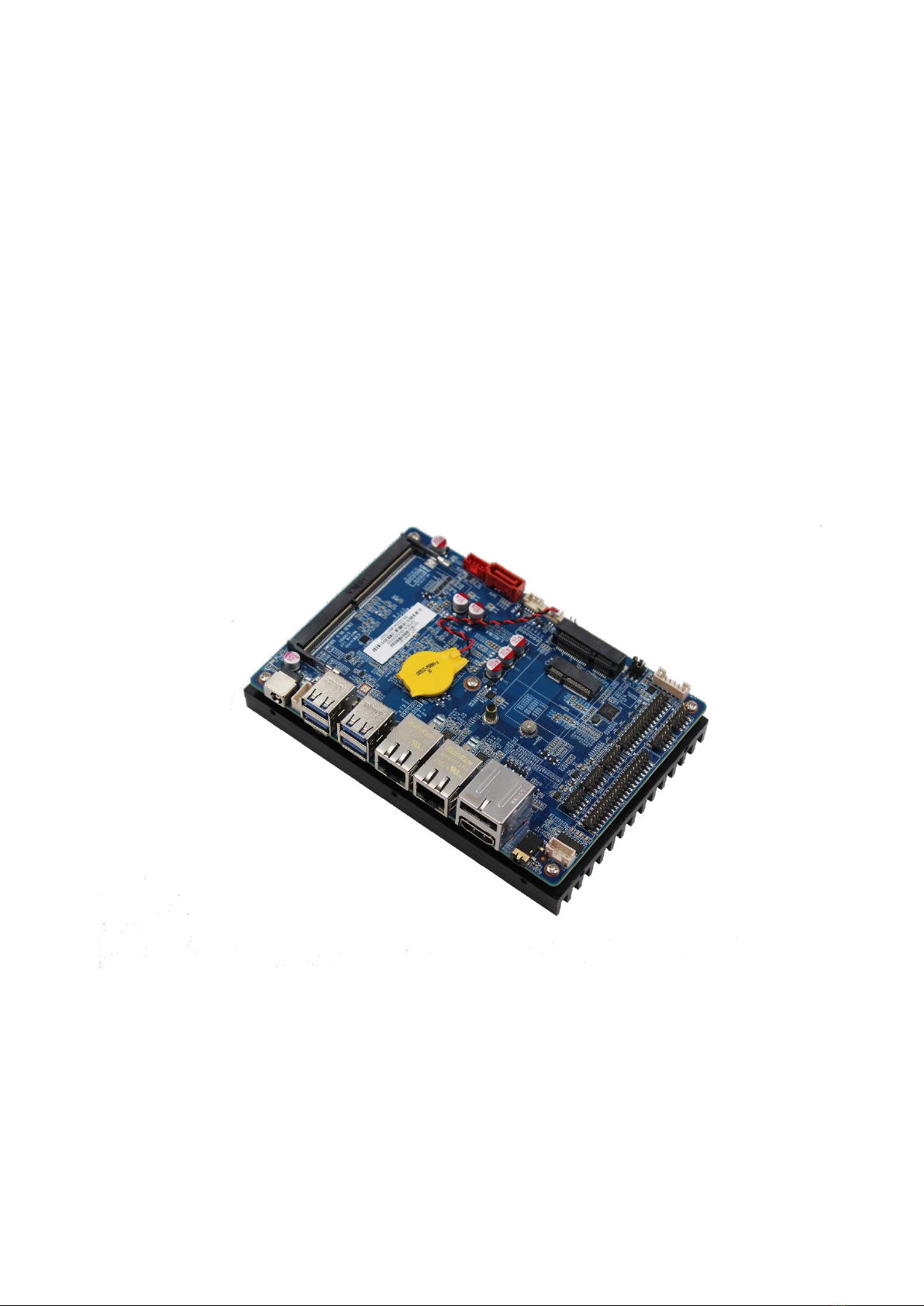
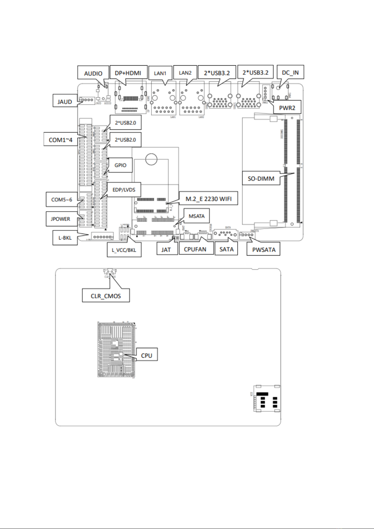
Connector Diagram .................................................................................................................................... 5
Chapter 2 Hardware................................................................................................. 6
Installations................................................................................................................................................ 6
Jumper Setting ........................................................................................................................................... 6
Memory Slots ............................................................................................................................................. 6
Display Interfaces....................................................................................................................................... 7
Storage (Screen Printing: MSATA, SATA1, PWSATA)................................................................................................ 9
Expansion Slot.......................................................................................................................................................... 9
USB Interface ........................................................................................................................................................... 9
LAN........................................................................................................................................................................... 9
COM ......................................................................................................................................................................... 9
GPIO (Screen Printing: GPIO) ................................................................................................................................. 11
Board Power Supply (Screen Printing: PWR2) ....................................................................................................... 11
Switch Button/Light Indicator (Screen Printing: JPOWER)..................................................................................... 11
Audio Interface ...................................................................................................................................................... 11
Hardware Auto Start (Screen Printing: JAT)........................................................................................................... 12
CMOS Clearance/Retention (Screen Printing: CLR_CMOS).................................................................................... 12
Chapter 3 BIOS Setup............................................................................................. 13
Entering the BIOS................................................................................................................................................... 13
Main Setup (BIOS info, Date, Time)..................................................................................................................... 13
Advanced Settings.................................................................................................................................................. 14
Power & Performance........................................................................................................................... 14
CPU-Power Management Control......................................................................................................... 15
GT-Power Management Control........................................................................................................... 16
Thermal Configuration .......................................................................................................................... 16
ACPI Settings ......................................................................................................................................... 17
IT8786 Super IO Configuration.............................................................................................................. 18
Hardware Monitor ................................................................................................................................ 19
Smart Fan Function ............................................................................................................................... 20

Watch Dog Configuration...................................................................................................................... 20
S5 RTC Wake Settings.......................................................................................................................... 21
USB Configuration ............................................................................................................................... 21
Network Stack Configuration .............................................................................................................. 22
NVME Configuration ........................................................................................................................... 23
Chipset ................................................................................................................................................................... 23
State After G3........................................................................................................................................ 24
Security .................................................................................................................................................................. 24
Boot........................................................................................................................................................................ 25
Save & Exit.............................................................................................................................................................. 26

Chapter 1 Product Introduction
Brief Introduction
The EHL-35 motherboard is a 3.5" SBC (Single Board Computer) based on the Intel Elkhart Lake platform,
which features a small form factor, low power consumption, and high performance.
Parameters
CPU: Intel® Celeron® Processor J6412, 4Cores 4Threads, Base Frequency: 2.00GHz, Burst Frequency: 2.60 GHz,
TDP 10W
Memory: 1x SO-DIMM DDR4-3200, maximum capacity 32GB
GPU: Integrated Graphics based on CPU, display via 1x HDMI2.0, 1Xdp1.4,1x LVDs (eDP optional)
Storage: 1 x mSATA interface or 4G module. 1 x SATA3.0 standard interface,
USB: 4x USB3.2 Gen 2, 4x USB2.0
Ethernet: 2x Gigabyte Network Controllers on-board (RTL8111H)
Audio: High-Definition Audio Codec, supports 1xCTIA Line_out + Mic_in in one
Serial I/O: 6x RS232 COM (COM5, COM6*RS485 optional)
Other I/O: 1x M.2_Key E for 2230 Wi-Fi & BT, 1xJPOWER, 1xSIM Slot, 1 set of GPIO pins
Dimension: 146mm x 102mm (3.5")
Power: 12V DC-in
Working Temperature: -20℃~60℃

Connector Diagram

Chapter 2 Hardware
Installations
Please refer to the following steps for installations:
1. Read the user manual carefully to make sure all the adjustments on the EHL35 are correct.
2. Installing the Memory:
Press the ejector tab of the memory slot outwards with your fingertips.
Hold the memory module and align the key to the module with that on the memory slot.
Gently push the module into the slot until the ejector levers return completely to the closed
position, holding the module in place when the module touches the bottom of the slot. To
remove the module, press the ejector levers outwards to unseat the module.
3. Installing the expansion cards:
Locate the expansion slots and remove the screw, insert the cards into the slot at a 45-degree
angle then attach the screw to the expansion cards, gently press down on it then install the
screw back.
4. Connect all signal wires, cables, panel control wiring, and power supplies.
5. Start the computer and complete the setup of the BIOS program.
The board's components are integrated circuits and can easily be damaged by Electrostatic Discharge or
ESD; therefore, please follow the instructions:
Hold the board's edge when handing, and do not touch onboard pins, components, or plug
sockets.
When touching integrated circuit components (such as CPU, RAM, etc.), please wear an anti-
static wrist strap/glove to avoid electrostatic discharge damage to the board or other sensitive
components.
Before installing the integrated circuits/sensitive components, place the sensitive components
in anti-static bags to keep them safe from ESD.
Please make sure the power switch is OFF before plugging the power plug.
Jumper Setting
Please configure the jumpers according to your requirements before installing the hardware.
How to identify the first header of jumpers and pins: Observe the mark beside the jumper or pins and
find the header marked by “1” or bold line or triangular symbol. Or observe the rear panel and the header
with a square solder pad is the first header.
Memory Slots
The board provides 1 x SO-DIMM DDR4-3200 slot, maximum capacity of 32GB.
Attention: Make sure to hold the memory module and align the key to the module with that on the
memory slot. While choosing a memory module, please make sure the module matches the board’s
specifications.

Display Interfaces
The board features Integrated Intel UHD graphics, supports 1xHDMI2.0b(HDCP2.3), 1xDP1.4, 4K
resolution at 60Hz. 1x 24bit LVDs (Resolution:1920x1080, eDP optional).
2.4.1 LVDS (Screen printing: EDP/LVDS, L-BKL, L_VCC/BKL)
When it is configured as an LVDS function, the "EDP/LVDS" pin transmits LVDS signals, the " L_BKL" pin is
the backlight adjustment jumper, and the "L_VCC/BKL" pin is the display working voltage adjustment jumper.
LVDS Data Pin (Screen printing: EDP/LVDS)
Signal
Pin
Signal
VCC
1
2
VCC
VCC
3
4
GND
GND
5
6
GND
A_DATA0_DN
7
8
A_DATA0_DP
A_DATA1_DN
9
10
A_DATA1_DP
A_DATA2_DN
11
12
A_DATA2_DP
GND
13
14
GND
A_CLK_DN
15
16
A_CLK_DP
A_DATA3_DN
17
18
A_DATA3_DP
B_DATA0_DN
19
20
B_DATA0_DP
B_DATA1_DN
21
22
B_DATA1_DP
B_DATA2_DN
23
24
B_DATA2_DP
GND
25
26
GND
B_CLK_DN
27
28
B_CLK_DP
B_DATA3_DN
29
30
B_DATA3_DP
LVDS Backlight Adjustment Pin (Screen printing: L-BKL)
Pin
Signal
1
GND
2
GND
3
LCD_BKL_ADJ
4
LCD_BKL_ON
5
12V
6
12V
LVDS Working Voltage Pin (Screen Printing: L_VCC/BKL)
Interface
Setting
Function
1-3
Close
VCC(+3.3V)
3-5
Close
VCC(+5V)
2-4
Close
REV (Backlight control reverse)
4-6
Close
STD (Backlight control standard)
Attention: When setting the LVDS display power supply jumper, it is adjustable between 5V/3.3V. The

customer can use a jumper cap to short-circuit the voltage pin according to the LVDS screen's voltage
parameters. (Please do not short-circuit two or more different voltages pins at the same time).
2.3.2 eDP (Optional)
When it is set as eDP functions, the “EDP/LVDS” pin transmits the eDP signal, the “L-BKL” is for the
backlight adjustment jumper and the “L_VCC/BKL” is for the display working voltage adjustment jumper.
eDP Data Pin (Screen Printing: EDP/LVDS)
Signal
Pin
Signal
VCC
1
2
VCC
VCC
3
4
EDP_HPD
GND
5
6
GND
EDP_AUXN
7
8
EDP_AUXP
N/A
9
10
N/A
EDP_DATA0_P
11
12
EDP_DATA0_N
GND
13
14
GND
N/A
15
16
N/A
EDP_DATA1_P
17
18
EDP_DATA1_N
N/A
19
20
N/A
N/A
21
22
N/A
N/A
23
24
N/A
GND
25
26
GND
N/A
27
28
N/A
N/A
29
30
N/A
eDP Backlight Adjustment Pin (Screen Printing: L-BKL)
Pin
Signal
1
GND
2
GND
3
LCD_BKL_ADJ
4
LCD_BKL_ON
5
12V
6
12V
EDP Working Voltage Pin (L_VCC/BKL)
Interface
Setting
Functions
1-3
Close
VCC(+3.3V)
3-5
Close
VCC(+5V)
2-4
Close
REV (Backlight control reverse)
4-6
Close
STD (Backlight control standard)
Attention: When setting the eDP display power supply jumper it is adjustable between 5V/3.3V.Short-
circuit pins of different voltages at the same time are strictly forbidden.

Storage (Screen Printing: MSATA, SATA1, PWSATA)
1x mSATA interface SATA2.0 onboard supports 4G module with standard Micro-SIM slot. 1x Standard
SATA interface. 1xPWSATA disk power supply socket (2.0mm spacing).
SATA Power Supply (Screen Printing: PWSATA)
Pin
Signal
1
5V
2
GND
3
GND
4
12V
(Same input voltage at the board)
Expansion Slot
The board provides 1xM.2 Key_E slot for 2230 Wi-Fi & Bluetooth.
USB Interface
The board supports 4x USB3.2 Gen2 and 4x USB2.0(2.0mm spacing).
Internal USB2.0 Pin (Screen Printing: USB20, USB21)
Signal
Pin
Signal
VCC 5V
1
2
VCC 5V
USB DATA-
3
4
USB DATA-
USB DATA+
5
6
USB DATA+
GND
7
8
GND
NC
9
10
(N/A)
LAN
The board features 2xRJ45 interfaces with high-speed Realtek 8111H Gigabit network controllers,
supports Magic packet wake-up, and the LAN1 supports PXE network boot.
LED Status Indicators:
LI_LED Status (Green)
Function
ACT_LED Status (Orange)
Function
Always on
Network Connected
Blinking
Data transfer
COM
The board provides six RS232 onboard serial port headers (2.0mm spacing), and the COM5 and COM6
are RS485 optional; screen printing COM14 is electrified, and the voltage is the same as the board’s input
voltage.
RS232 COM (Screen Printing: COM14)
Signal
Pin
Signal
DCD#
1
2
RXD
TXD
3
4
DTR#

GND
5
6
DSR#
RTS#
7
8
CTS#
RI#
9
10
VCC (same as board’s input voltage)
DCD#
11
12
RXD
TXD
13
14
DTR#
GND
15
16
DSR#
RTS#
17
18
CTS#
RI#
19
20
VCC (same as board’s input voltage)
DCD#
21
22
RXD
TXD
23
24
DTR#
GND
25
26
DSR#
RTS#
27
28
CTS#
RI#
29
30
VCC (same as board’s input voltage)
DCD#
31
32
RXD
TXD
33
34
DTR#
GND
35
36
DSR#
RTS#
37
38
CTS#
RI#
39
40
VCC (same as board’s input voltage)
COM5_6 RS232 Default (Screen: COM5_6)
Signal
Pin
Signal
NC
1
2
NC
RX5
3
4
RX6
GND
5
6
GND
TX5
7
8
TX6
NC
9
10
(NC)
COM5_6 RS485 Optional (Screen Printing: COM5_6)
Signal
Pin
Signal
COM5_DATA-
1
2
COM6_DATA-
COM5_DATA+
3
4
COM6_DATA+
GND
5
6
GND
NC
7
8
NC
NC
9
10
(NC)

GPIO (Screen Printing: GPIO)
The board provides a set of 2x5Pin GPIO (2.0mm spacing) 8 programmable I/O lanes in total.
GPIO (Screen Printing: GPIO)
Signal
Pin
Signal
SIO_GP70
1
2
3.3V
SIO_GP71
3
4
SIO_GP74
SIO_GP72
5
6
SIO_GP75
SIO_GP73
7
8
SIO_GP76
GND
9
10
SIO_GP77
Board Power Supply (Screen Printing: PWR2)
The board provides a 5.5mm*2.5mm DC power interface, and a 2x2 ATX power supply interface supports
12V DC-in.
PWR2 (Screen Printing: PWR2)
Pin
Signal
1
VCC
2
VCC
3
GND
4
GND
Switch Button/Light Indicator (Screen Printing: JPOWER)
The board has a set of 2.0mm spacing pins that can be connected to a switch button, a system reset
button, a hard disk read/write indicator, and a power-on indicator.
JPOWER (Screen Printing: JPOWER)
Signal
Pin
Signal
HDD_LED+
1
2
PWR_LED+
HDD_LED-
3
4
PWR_LED-
RSTBTN-
5
6
PWR_ON+
RSTBTN+
7
8
PWR_ON-
NC
9
10
(NC)
Audio Interface
The board features a Realtek HD audio codec, supports a 3.5mm Line-out/MIC two-in-one combo jack
(CTIA American standard), and a built-in dual-channel power amplifier output socket for connecting passive
speakers.

Two-in-one headphone jack:
JAUD (Screen Printing: JAUD)
Pin
Signal
1
L+
2
L-
3
R-
4
R+
Hardware Auto Start (Screen Printing: JAT)
JAT (Screen Printing: JAT)
Setting
JAT
Close
Hardware Auto Start
Please note that this jumper’s function is similar to the BIOS’s “State After G3” function. When the latter
is set to “S0 State”, the device will start automatically after being connected to power.
CMOS Clearance/Retention (Screen Printing: CLR_CMOS)
CMOS is powered by onboard button batteries. Clearing CMOS will permanently remove the previous
system settings and restore the board system to original settings (factory settings).
Step 1: Turn off the PC and disconnect the power adapter.
Step 2: Press CLR_CMOS for 10 seconds then disconnect.
Step 3: Restart the device, press the <DEL> button to enter the BIOS, load the optimal default value,
save, and exit the settings.
CMOS (Screen Printing: CLR_CMOS)
Setting
CLR_CMOS
Close
Clear CMOS
Please do not clear COMS when the PC is connected to power in case board damages.

Chapter 3 BIOS Setup
Entering the BIOS
1. Turn on the computer and press <Delete> entering the BIOS
2. After the computer is turned on, keep press F11, choose enter Setup
3. BIOS Hotkeys:
F9: Restore to Factory setting; F10: Save and Exit; ESC: Exit
Main Setup (BIOS info, Date, Time)
When you enter the BIOS Setup utility the first things you will encounter is the Main Setup screen.
Shown below is the Main BIOS Setup screen. You can always return to the Main setup by selecting the Main
tab.
System Date: Sets the date. MM/DD/YY format.
System Time: Set the time. HH:MM: SS format.

Advanced Settings
Select any of the items in the left frame of the screen. The advanced sections allow you to configure,
improve and set up system features according to the preference of the CPU Configuration. All Advanced BIOS
Setup options are described as follows.
Power & Performance
CPU-Power Management Control
GT-Power Management Control

CPU-Power Management Control
Intel® Speedstep®(TM):
Enhanced Intel SpeedStep® Technology enables the operating system to control multiple frequencies and
voltage points for optimal performance and power efficiency.
Intel® Speed Shift Technology:
An energy-efficient frequency control method by the hardware rather than relying on OS control.
Processor decision is based on the different system constraints for example Workload demand, and thermal
limits while taking into consideration the minimum and maximum levels and activity window of performance
requested by the operating system. Default enabled.
Turbo Mode
The Turbo mode refers to Nehalem’s “Integrated Power Gate” power management technology, which
allows running off some cores and adding power to the others so that they run at a higher frequency. The
capacity of the entire CPU remains unchanged, and the efficiency of the CPU is optimized. Default enabled.
C states
Idle States (C-states) are used to save power when the processor is idle. C0 is the operational state,
meaning that the CPU is doing useful work 100% load. C1 is the first idle state, C2 the second, and so on,
where more power-saving actions are taken for numerically higher C-states. C1 to C3 cuts off the clock inside
the CPU, and C4 to C6 reduces the CPU voltage. Default enabled.
Enhanced C states
C1 to C3 cuts the clock inside the CPU. C4 and C6 mode reduces CPU voltage. Features two way
“Enhanced” mode, enable by default.

GT-Power Management Control
Maximum GT frequency:
Maximum GT Frequency, Default max frequency.
Disable Turbo GT frequency:
Disable Turbo GT Frequency mode, Default disabled.
Thermal Configuration

Enable All Thermal Functions
CPU Thermal Configuration:
Unlocks the temperature setting, the “Tcc Activation Offset” is the temperature adjustment option,
the highest temperature is 105°C. Change the temperature by minus the number of degrees you wish to
change. For example, minus 0(105-0) to set the temperature at 105°C, minus 20(105-20) to set the
temperature at 85°C.
Platform Thermal Configuration
DPTF Configuration
ACPI Settings
Enable ACPI Auto Configuration
Enable or disable BIOS ACPI Auto Configuration.
Enable Hibernation
Enable or disables the ability to hibernate.
ACPI Sleep State
Select the highest ACPI sleep state the system will enter when the SUSPEND button is pressed.

IT8786 Super IO Configuration
Serial Port 1 Configuration
Set parameters of serial port 1.
Serial Port 2 Configuration
Set parameters of serial port 2.
Serial Port 3 Configuration
Set parameters of serial port 3.
Serial Port 4Configuration
Set parameters of serial port 4.
Serial Port 5 Configuration
Set parameters of serial port 5.
Serial Port 6 Configuration
Set parameters of serial port 6.
Serial Port: Enable or disable serial port(COM).
Device Setting (Read-only): Displays serial ports’ interrupt and location.
Change Setting: Change serial port settings and suggest setting “Auto” as default.

Hardware Monitor
PC Health Status
The PC health status displays CPU temperature, system temperature, fan speed, and other relevant
voltage values. The above parameters have a certain range, and the system cannot run beyond these
ranges.
CPU Temperature
System Temperature
VCore: Core Voltage
VDDQ: RAM Voltage
+3.3V: 3.3V
+5V: 5V

Smart Fan Function
Smart Fan Mode
Automatic Mode
Full-on Mode
Manual Mode
Watch Dog Configuration
WDT Timeout Mode select: Minute or Second
Table of contents
Other Maxtang Motherboard manuals

Maxtang
Maxtang FP-10 User manual

Maxtang
Maxtang BYT-35 User manual

Maxtang
Maxtang SKD70 User manual

Maxtang
Maxtang EHL-35 User manual

Maxtang
Maxtang MITX-BYT70 User manual

Maxtang
Maxtang APL-35 User manual

Maxtang
Maxtang EHL-10 User manual

Maxtang
Maxtang WL10 User manual

Maxtang
Maxtang FP50 User manual

Maxtang
Maxtang MITX-KL10 User manual

Maxtang
Maxtang WL35 User manual

Maxtang
Maxtang BYT-35 SBC User manual

Maxtang
Maxtang SKD70 User manual

Maxtang
Maxtang WL10 User manual

Maxtang
Maxtang BW-35 User manual

Maxtang
Maxtang FP20 User manual

Maxtang
Maxtang ALN50 User manual

Maxtang
Maxtang DTJ6412-A User manual

Maxtang
Maxtang JSL-15 User manual

Maxtang
Maxtang WL35 User manual