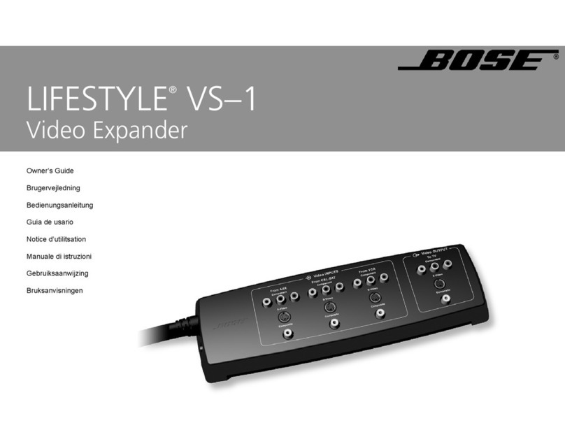
Bose Lifestyle VS-1 User manual

VIDEO
EXPANDER
Owner's Guide
Brugervejledning
Bedienungsanleitung
Gufa de usario
Notice d'utilitsation
Manuale di istruzioni
Gebruiksaanwijzi
ng
Bruksanvisningen

IMPORTANT
SAFETY
INFORMATION
1.
Read
these
instructions -for all components before using this product.
2.
Keep
these
instructions -for future reference.
3.
Heed all warnings -
on
the product and
in
the owner's guide.
4.
Follow all instructions.
5.
Do not use this apparatus
near
water
or
moisture -Do not use this product near abathtub, washbowl, kitchen
sink, laundry tub,
in
awet basement, near aswimming pool, or anywhere
else that water
or
moisture are present.
6. Clean only
with
adry cloth -and as directed by
Bose®
Corporation.
Unplug this product from the wall outlet before cleaning.
7. Do
not
block any ventilation openings. Install in accordance with
the
manufacturer's instructions -
To
ensure reliable operation
of
the
product and
to
protect it from overheating, put the product
in
aposition and
location that will not interfere with its properventilation. For example,
do
not
place the product on a bed, sofa,
or
similar surface that may block the ven-
tilation openings. Do not put it
in
abuilt-in system, such as abookcase or a
cabinet that may keep air from flowing through its ventilation openings.
8.
Do not install
near
any
heat
sources, such as radiators,
heat
regis-
ters, stoves or
other
apparatus (including amplifiers)
that
produce
heat.
9. Do not
defeat
the
safety purpose
of
the
polarized
or
grounding-
type plug. Apolarized plug has
two
blades with one
wider
than
the
other. Agrounding-type plug has
two
blades and athird grounding
prong.
The
wider
blade or third prong
are
provided
for
your safety.
If
the
provided plug does not
fit
in your outlet, consult an
electri-
cian for
replacement
of
the
obsolete outlet.
10.
Protect
the
power cord from being
walked
on
or
pinched, particu-
larly
at
plugs, convenience receptacles, and
the
point
where
they
exit from
the
apparatus.
11.
Only use attachments/accessories specified by
the
manufacturer.
12.
Use only with
the
cart,
stand, tripod,
bracket
or
table
<Il
specified by
the
manufacturer
or
sold
with
the
appara-
~
tus. When a
cart
is used, use caution
when
moving
the
•
~,
cart/apparatus
combination
to
avoid injury from
tip-
~
over.
13.
Unplug this apparatus during lightning storms or
when
unused for
long periods
of
time
-to prevent damage
to
this product.
2
14.
Refer
all servicing to qualified service personnel. Servicing is
required
when
the
apparatus has been damaged in any way: such
as power-supply cord
or
plug is damaged; liquid has been spilled
or
objects have fallen into
the
apparatus;
the
apparatus has been
exposed
to
rain
or
moisture, does not
operate
normally,
or
has
been
dropped -Do not attempt to service this product yourself. Opening
or
removing covers may expose you to dangerous voltages
or
other haz-
ards. Please call Bose
to
be referred
to
an
authorized service center near
you.
15.
To
prevent risk of fire
or
electric shock, avoid overloading wall out-
lets, extension cords, or integral convenience receptacles.
16.
Do not
let
objects or liquids
enter
the
product -as they may touch
dangerous voltage points
or
short-out parts that could result
in
afire
or
electric shock.
17.
See
product enclosure bottom for
safety
related markings.
Information
about
products
that
generate
electrical
noise
If applicable, this equipment has been tested and found
to
comply with the lim-
its for aClass Bdigital device, pursuant
to
Part 15
of
the FCC rules. These limits
are designed to provide reasonable protection against harmful interference
in
a
residential installation. This equipment generates, uses, and can radiate radio
frequency energy and, if not installed and used in accordance with the instruc-
tions, may cause harmful interference
to
radio communications. However, this
is
no guarantee that interference will not occur
in
aparticular installation. If this
equipment does cause harmful interference
to
radio
or
television reception,
which can be determined by turning the equipment off and on, you are encour-
aged
to
try
to
correct the interference by one
or
more ofthe following measures:
•Reorient
or
relocate the receiving antenna.
•Increase the separation between the equipment and receiver.
•Connect the equipment
to
an
outlet
on
adifferent circuit than the one to which
the receiver
is
connected.
•Consult the dealer
or
an
experienced radiolTV technician for help.
NOT
E:
Unauthorized modification
of
the receiver
or
radio remote control could
void the user's authority to operate this equipment.
This product complies with the Canadian ICES-003 Class Bspecifications.

SAFETY
INFORMATION
Please
read
this installation guide
Please take
the
time
to
follow
this installation guide carefully. It will help you set
up
and operate
your
system properly, and enjoy all
of
its advanced features. Save your
installation gUide for future reference.
~
WARNING:
To
reduce the risk
of
fire
or
electric shock, do
not
expose the system to
rain
or
moisture.
~
WARNING:
This
apparatus shall
not
be
exposed to dripping
or
splashing,
and
objects filled with liquids, such as vases, shall
not
be
placedon the apparatus.
As
with
any electronic products, use care
not
to spill liquids
in
any
part
of
the system. Liquids
can cause afailure
and/or
afire hazard.
CAUTION:
TO
REDUCE
THE
RISK
OF
ELECTRIC
SHOCK,
DO
NOT
REMOVE
COVER
(OR
BACK).
NO
USER-SERVICABLE
PARTS
INSIDE.
REFER
SERVICING
TO
QUALIFIED
PERSONNEL.
ATIENTION :
POUR
REDUIRE
LE
RISQUE
DE
DECHARGE
ELECTRIQUE,
NE
RETIREZ
PAS
LE
COUVERCLE
(OU
L'ARRIERE).
IL
NE
SE
TROUVE
A
L'INTERIEUR
AUCUNE
PIECE
POUVANT
ETRE
REPAREE
PAR
L'USAGER.
S'ADRESSER
A
UN
REPARATEUR
COMPETENT.
&The lightning flash with arrowhead symbol, within an equilateral triangle,
is
intended to alert the user
to
the
presence
of
uninsulated dangerous volt-
age within the system enclosure
that
may
be
of
sufficient magnitude
to
constitute arisk
of
electric shock.
&. The exclamation point within an equilateral triangle, as marked on the sys-
tem, is intended
to
alert
the
user
to
the presence
of
important operating
and maintenance instructions in this installation guide.
ACAUTION: No naked flame sources, such as lighted candles, should
be
placed on
the apparatus.
( EThis
product
conforms
to
the EMC Directive 89/336/EEC and
to
the
Low Voltage
Directive 73/23/EEC. The complete Declaration
of
Conformity can be found on
www.bose.com.
©2005 Bose Corporation. No part
of
this work may
be
reproduced, modified, distributed
or
otherwise
used without priorwritten permission. All trademarks referenced herein are property
of
Bose Corporation.
3

CONTENTS
Introduction
.............•.•..•....••...............
5
About your
LI
FESTYLE®
system
VS-1
video expander . . . . . . . . . .
..
5
Unpacking 5
Finding alocation for the
VS-1
5
Connecting
the
VS-1
to
Your
Media
Center
6
If you have a
L1FESTYLE®
system
in
your home " 6
Connecting the Quadra cable .............................
..
6
Your
Connection
Options 7
Your TV connection panel ................................
..
7
Choosing the TV connection type ..........................
..
7
For
a
Component
Connection
Between
Your
TV
and
the
VS-1
.•
8
Connecting your TV
to
the
VS-1
(Component) 8
Choosing connection types for your video sources 9
Connecting your sources to the
VS-1
9
For
an
S-Video
Connection
Between
Your
TV
and
the
VS-1
10
Connecting your
TV
to the
VS-1
(S-Video) 10
Choosing connection types for your video sources
11
Connecting your sources to the
VS-1
11
For
a
Composite
Connection
Between
Your
TV
and
the
VS-1
..
12
Connecting your
TV
to the
VS-1
(Composite) .................
..
12
Connecting your sources
to
the
VS-1
13
Source
Audio
Connections
. . . . . . . . . . . . . . . . . . . . . . . . . . •
..
14
Program Recording Connections
15
Connecting your cable/satellite
box
to
your VCR/OVR ..........
..
15
Recording programs 15
Operating
Information
..••..•.•..•.•..•...............
16
Updating the system software. ............................
..
16
Activating component video 16
Switching sources ......................................
..
17
Mounting
Your
VS-1 on aWall
18
Required tools .........................................
..
18
Recommended hardware 18
Maintaining
Your
VS-1
19
Cleaning. .............................................
..
19
Troubleshooting ........................................
..
19
Technical information 20
Contacting Customer Service .............................
..
20
Limited
Warranty.
......................................
..
21
4

Introduction
About your LIFESTYLE® system
VS-1 video
expander
The
LIFESTYLE®
system
VS-1
video expander is designed to sim-
plify your system setup and operation. After setting up the VS-1,
pressing asource button on your
LIFESTYLE®
system remote
selects audio and video at the same time.
•Designed
to
work with
LIFESTYLE®
48, 38, 28 Series
II
and 18
Series
II
DVD
home entertainment systems.
•Provides component, S-Video, and composite video outputs for
your
TV.
•Provides component, S-Video, and composite inputs for your
VCR, cable/satellite box, or other audio/video source.
•Converts acomposite input
to
an
S-Video or component output;
converts
an
S-Video input
to
acomponent output.
•Compatible with high-definition
TV
(HDTV)
and progressive scan
TV formats.
VS-1
video
expander
Software update disc
Unpacking
_
~
WARNING:
To
avoid danger
of
suffocation, keep the
~
plastic bags
out
of
the reach
of
children.
Carefully unpack the
VS-1
video expander. Check
to
be sure your
system includes the parts shown on this page. Save all packing
materials
in
case you need
to
repack and transport your product.
If any part of the product appears damaged, do not attempt to use it.
Notify Bose or your authorized Bose dealer immediately. For Bose
contact information, refer to the address sheet included
in
the carton.
Finding alocation
for
the
VS-1
You
can position the
VS-1
on ashelf behind your media center or
behind your
TV,
oryou can mount it on the back
of
an
entertainment
center
or
on awall.
To
mount it on awall, see "Mounting Your
VS-1
on aWall" on page 18.
If
you need additional
cabl~s
Your
VS-1
includes one component video cable. Additional cables may be needed
to
set
up the
VS-1with
your
LIFESTYLE®
system.
To
determine ifyou need any additional cables,
we
suggest that you read through this guide before
you.beginthe
actual setup. Additional
cables can be purchased from your Bose dealer
or
your local electronics retailer.
For your records
Now
is agood time to find the serial number on the bottom
of
the
VS-1
video expander.
Please record it here. This provides easy access
to
this number if you ever need
to
con-
tact
Bose®
Customer Service.
Serial number: _
Dealer name: _
Dealer phone: _Purchase date: _
Please keep your sales receipt with this owner's guide.
5

Connecting
the
VS-1
to
Your
Media
Center
If
you have aLIFESTYLE® system
in your
home
If you already have set up a
LIFESTYLE®
system
in
your home, complete the following steps. Other-
wise, skip to "Connecting the Quadra cable."
1.
Turn off your
LIFESTYLE®
system.
2.
Unplug the media center power module and
disconnect the
DC
power cord from the media
center.
3.
Remove any video cables from the Video OUT
and Video
IN
jacks on the media center.
Video cables
Media
center
power
module
Connecting
the
Quadra
cable
Connect the Quadra cable from the
VS-1
video
expander to the back
of
your media center:
1.
Insert the plug labelled "Serial Data" into the
Serial Data jack on the media center.
2.
Insert the plug labelled "DC Power" into the
DC
Power jack on the media center.
3.
Insert the plug labelled "Composite Video" into
the Composite Video OUT jack on the media
center.
4.
Insert the plug labelled "S-Video" into the
S-Video OUT jack on the media center.
5.
Connect the
DC
power cable from the media
center power module to the
DC
Power
IN
jack
on the end
of
the
VS-1
video expander.
6
.A.
WARNING:
The
VS-1
must
be
used only with the media center
power
supply module that came
with
your
LIFESTYLf!&
OVO
home
entertainment system. Serial Data
Media
center
rear
panel
/
DC
Power
IN
S-Video

Your
Connection Options
Your
TV
connection panel
Your TV may have more than one type
of
video input
connection. Each type provides adifferent level
of
video image quality.
Examine the rear panel
of
your
TV
and determine
whether it has composite, S-Video, or component
video input jacks.
S-Video
Good quality
Composite
Standard quality
\fellow)
Component
Best quality
(Green)
I
(Blue)
•(Red)
This
is
only an example
ofa
TVc.onnection
panel. Your
TV
may
not
have
the
exact
same
number and types
of
connections.
Refer
to
the
owner's
guide
that
came
with your
TV.
TV
connection panel
Choosing
the
TV
connection
type
From the video input jacks on the back
of
your
TV,
choose the type that provides the highest level
of
video image quality. Place acheck mark next
to
the
type
of
video input connection you plan to use.
Your choice determines which page you turn
to
for
instructions on connecting your TV and other video
sources
to
your
VS-1
:
•
If
you chose Component, go to page
8.
•
If
you chose S-Video, go to page
10.
•
If
you chose Composite, go to page
12.
Check
TVconnection
one type
Component
DY
Pb
Pr
S-Video
D
Video
Quality
Best
Good
Cable Type
Supplied with the
VS-1
To
help you
make
color-
coded connections, a
color guide is provided
inside
the
back
cover.
Composite
oStandard
Supplied with your LIFESTYLE system
7

For
a
Component
Connection
Between
Your
TV
and
the
VS-1
...
........... (Blue)
TV
connection
panel
Component video
cable (supplied)
When
switching
between.sources using a
component
connection,lhe.VS-1·componenloutputmay·sometimes
changie between aprogressive
scan
format
and
anon-
progressive scan format.
Some
TVs
may
not
be
able
to
handle bothiinterlaced
and
HD
formats
on
the
same
input. Please refer
to
your
TV owner's
guide
to
learn
about
the
component
input
capabilities
of
your
TV.
For
best
video
performanc.e, you·
must
activ.ate
the
component
video
function
in
your
media
center.
For
instructions,.
see"
Activating
component
video"
on
pagel6.
Connecting
your
TV
to
the
VS-1
(Component)
Follow the instructions on this page and the next if you decided
to
connect
your TV
to
the
VS-1
using acomponent video cable.
You
can use the component video cable included
in
the carton to connect
your TV
to
the
VS-1
.
1.
Plug one end
of
the component video cable into the component jacks
on the rear
of
your
TV.
Be sure
to
match the color
of
each plug
to
the
color
of
each jack.
2.
Plug the other end
of
the component video cable into the
Video
OUTPUT
Component
jacks on the VS-1. Again, be sure to match
the color
of
each plug
to
the color
of
each jack.
3.
Turn
to
page 9for instructions on connecting your video sources to the
VS-1.
8

Choosing
connection
types
for
your
video
sources
1.
Look at the rear panel
of
all your sources
to
determine what types
of
video output con-
nectors they have.
2.
In
the following table, check off the type
of
video input connection you plan to use for
each
of
your video sources. Choose the type
of
connection that provides the highest
level
of
video image quality.
We
recommend using acomponent connection if it is
available.
If
any
of
your
sources
do
not
havecomponentvideoiJacks,
you caniuse
eithe.r aniS-Video.or
Composite
connection.
Remember,
theVS-1
converts
either
of
these
up
to
component
video
format. VCR
I:i:@
II
====21
AUX CBL·SAT VCR
Best
S-Video Good
Connection
type
Component
Y
Pb
Pr
If_I_.
D
D
D
D
D
D
AUX
VCR
CBL-SAT
(Other)
Connecting
your
sources
to
the
VS-1
1.
Plug one end
of
the appropriate video cable into the selected jack(s) on your video
source. If you are making acomponent connection, be sure to match the color
of
the
plug
to
the color
of
the jack.
2.
Plug the other end
of
the video cable into the appropriate
Video
INPUT
jack(s) on the
VS-1. Again, if you are making acomponent connection, be sure to match the color
of
the plug
to
the color
of
the jack.
3.
Turn
to
"Source Audio Connections" on page 14.
AUX
CBL·SAT
I~
c=J
!I
I=
000000
CI
=====::J
StandardComposite
o
DD
D
9

For an S-Video Connection
Between
Your
TV
and
the
VS-1
Connecting your
TV
to
the
VS-1 (S-Video)
Follow the instructions on this page and the next if you decided
to
connect your TV
to
the
VS-1
using
an
S-Video cable.
You
can use the S-Video cable included with your
LIFESTYLE®
system
to
make this connection.
1.
Plug one end
of
the S-Video cable into the S-Video jack on the
rear
of
your
TV.
2.
Plug the other end
of
the S-Video cable into the Video OUTPUT
S-Video jack on the
VS-1
.
3.
Turn to page
11
for instructions on connecting your video sources
to
the VS-1.
~~~uuDDOOOOODDOOODDDD
~~uuuDDOOOOODOOODDDDD
~~~uuDDOOOOOODOODDDDD
~~~uuDDOOOOODDODDDDDD
~~uuuDDOOOOODDOODDDDD
VIDEO
IN
AUDIO
IN
TV
connection
panel
VS-1
S-Video cable
(Supplied with
your LIFESTYLE
system.)
10

Choosing
connection
types
for
your
video
sources
If you connected your
TV
to
the
VS-1
using
an
S-Video cable, you can only use S-Video
and Composite connections for source inputs even though asource may have
compo-
nent output connections.
1.
Examine the rear panel
of
all your source devices to determine what types
of
video
output connectors they have.
2.
In
the following table, place acheck next
to
the type
of
video input connection
you plan
to
use for each
of
your video sources. Choose the type
of
connection that
provides the highest level
of
video image quality.
We
recommend using
an
S-Video
connection if it is available.
AUX CBL·SAT VCR
VCR
Ifany
of
your
sources
do
not
have an S-Video jack,
you
can use a
Composite
connection. Remember,
the
VS-1 converts
this
up
to
S-Video format.
AUX
VCR
CBL-SAT
(Other)
Connection
type
Video
Quality
I
000
Ogo
II
III
c::::J
=====,
c::=:J c::=:J
(i)t-
DO NOT USE
(:::::-
...
-:\
\0)
o
Connecting
your
sources
to
the
VS-1
After obtaining the cable(s) you need:
1.
Plug one end
of
the video cable into the appropriate jack on the rear
of
your video
device.
D
D
D
D
D
D
S-Video Good
Composite Standard
oCBL·SAT
I
~
c:::::::J
!I
VIDEO
OUT
AUX
DO NOT USE
2.
Plug the other end
of
the video cable into the appropriate
Video
INPUT
jack(s) on
the VS-1.
3.
Turn to "Source Audio Connections" on page 14.
1=
000000
1'----_------'1
I
VIDEO
OUT
DO NOT USE
11

For aComposite Connection
Between
Your
TV
and
the
VS-1
Connecting your
TV
to
the
VS-1 (Composite)
Follow the instructions on this page and the next if you decided
to
connect your TV
to
the
VS-1
using acomposite video cable.
You
can use the composite video cable included with your
LIFESTYLE®
system to make this connection.
1.
Plug one end
of
the composite video cable into the composite video
jack on the rear
of
your
TV.
2.
Plug the other end
of
the composite video cable into the Video
OUTPUT Composite jack on the
VS-1
.
3.
Turn to page 13 for instructions on connecting your video sources to
the VS-1.
~~~DDDQQOOOOOOOOODDDD
~~DDDQQOOOODOOOODDDDD
~~DDDDQOOODOOOOOODDDD
~~DDDQQOODDDOOOODDDDD
~~DDDQQOODDOOOOODDDDD
TV
connection
panel
VS-1
Composite cable
(Supplied with
your LIFESTYLE
system.)
12

Connecting your sources
to
the
VS-1
If you connected
your
TV
to
the VS-1 using a
composite
video cable, you
can only use composite connections
for
source inputs.
You
need
to
obtain a
composite
video cable
to
make this connection.
1.
Plug one end
of
the
composite
video cable into the
composite
jack
on
the video source.
2.
Plug the other end
of
the composite video cable into the composite
Video
INPUT
jack
on the VS-1 .
3.
Turn
to
"Source Audio Connections" on page 14.
AUX CBL·SAT VCR
VCR
I
000
a'Bo
II
21
c::::::J
<::::)
=====
c::::::J
DO NOT USE
CBL·SAT
I
:=.,
c::=:::J
AUX
I=
000000
I I I
c::::::J c::::::J
VIDEO
OUT
DO NOT USE
DO NOT USE
13

Source Audio Connections
Now that all the video connections are made, you can
connect the audio sources
to
the media center.
Connect the audio OUTjacks from all your sources to
the appropriate audio
IN
jacks on the rear panel
of
your
LIFESTYLE®
media center.
For more information on connecting audio sources to
the media center, refer to your
LIFESTYLE®
system
installation guide.
AUX
1=
000000
:;;;1
VCR
I~OgO
II
====21
TV
CBL·SAT
II
O~O
I
\Bllil;
I
1/
LIFESTYLE® media
center
rear
panel
14

Program Recording Connections
VCR
OR
DVR
CBL·SAT
1
000
OgO
II
21
c:::J
c:::::Jc:::::Jc:::::Jc:::::Jc:::::J
c:=::::J
Previously
made
connections
I=
c:::J
egO
I
L::::J L::::J
G+VIDEO
OUT
-e
VIDEO OUT
Y
Po
PR
(i-.-
Y
Po
PR
(i-.-
VIDEO 0
SVIDEO Q
SVIDEO Q
VIDEO
\e
-e
VIDEO
IN
-e
VIDEO OUT
Y
Po
PR
(i-.-
Y
Po
PR
(i-.-
SVIDEOQ
VIDEO
(1';\
~
SVIDEO Q
VIDEO
(~./
\;I
-e
AUDIO
IN
Digital
Digital
G+
AUDIO 2OUT
G+
AUDIO OUT
G+
AUDIO 1OUT
Previously
made
connections
Connecting your
cable/satellite
box
to
your
VCR/DVR
If you occasionally want to record programs from your
cable service, you need to connect your cable/satellite
box to your
VCR
or DVR. The diagram
on
this page
is
an
example of how this equipment might typically be
connected.
Before you start, make sure that your cable/satellite box
and VCR/OVR have the necessary inputs and outputs
available.
CD
Connect an unused video output
on
your
cable/
satellite box to
an
unused video input
on
your
VCR/OVR. Choose the connection type that provides
the highest level of image quality. Refer to page 7.
®
Connectan
unused audio output
on
your
cable/
satellite box to an unused audio input
on
your
VCR/OVR.
Recording programs
Your LIFESTYLE system does not need to select the
source you want to record.
You
can potentially watch one
program source while recording another.
15

Operating Information
Updating
the
system
software
Your
DVD
home entertainment system might need asoftware update
to
enable it
to
operate the VS-1. For example, if you cannot see apicture on your TV after installing
the
VS-1
,you need
to
update the system software. Asoftware update disc is
included
in
the carton with your
VS-1
.
To
run the software update disc:
1.
Turn on your
LIFESTYLE®
system.
2.
Load the software update disc into the disc player.
3.
Follow the instructions included with the software update disc.
Activating component video
To
use acomponent video connection between your TV and media center, complete
the following steps to enable your media center to output component video signals.
This must be done before you can view any video image on your
TV.
1.
Make sure your media center is turned off.
2.
Lift up the front
door
of
the media center
to
access the control buttons.
3.
Press and hold Enter.
4.
Press
Store
as many times as necessary until VIDEO appears on the media
center display.
5.
Release the
Enter
button.
6.
Press Volume up or down until the video setting you want is displayed:
•NTSC COMPONENT -for acomponent only connection
in
North America
•
PAL
COMPONENT -for acomponent only connection outside North America
•NTSC PROGRESSIVE -for acomponent connection
and
progressive scan
in
North America
(PAL
progressive is not supported)
7.
Press Store to confirm the selection and return the system
to
normal operation.
16
Disc tray
Media center
control buttons
Front panel door-lifts up
Display window

Switching sources
After adding the
VS-1
to
your system setup, switching sources is greatly
simplified. Just press the remote button (CD/DVD, VCR, CBUSAT, orAUX)
for the source you want to use. If you select one
of
the sources connected
to the VS-1, make sure the source is turned on.
Selecting
the
TV
source
If you select the
TV
source, you will hear the audio source that is con-
nected
to
the TV audio input jack on your media center, but your
TV
will
display the video
of
the last video source selected.
You
may need
to
select
another video input on yourTV to see the corresponding video. When you
press TV on the remote, "Choose
TV
INPUT" appears on the media center
display, reminding you
to
switch TV inputs if necessary.
Selecting anon-video source
If you select anon-video source (such as FM, AM, audio
CD),
the
VS-1
continues
to
send the output
of
the last-selected video source to your
TV
screen. This feature allows you
to
view the video portion
of
aprogram on
your TV while listening
to
the audio portion from another source. For
example, you can watch aball game while listening
to
the program audio
from alocal radio station.
17

Mounting Your VS-1 on aWall
Recommended
hardware
Required tools
Lower the
VS-1
onto the screws
to
lock it
in
place.
®
f1\ Install
two
screws eight inches
\.V
apart. Leave
1,4
in
(6
mm) between
wall surface and screw head.
®Position the
VS-1
over the screws
so that it is flush with the wall.
awmnmttttttttttttttt>
No.8
x
1Y2-in
(M4 x36 mm)
wood screws
For solid wood
~
Ys-in
(3.5 mm) drill bit
No.8(M4)
~~1
wall anchor
...
7"'.-C-,
I
~
Use drill size
specified for
type
of
wall
anchor used.
a",
---
0
NO.8 x
1Y2-in
(M4 x36 mm) wood or machine
screws (depends on type
of
wall anchor)
For wallboard
18

Maintaining Your VS-1
Cleaning
•Use only asoft, dry cloth
to
clean the outside
of
the
VS-1
.
•Do not use any solvents, chemicals, or cleaning solutions containing alcohol, ammonia, or abrasives.
•Do not allow liquids to spill into any openings.
•
Do
not use any sprays near the VS-1.
Troubleshooting
Problem
System will not turn on
No picture on TV
The wrong picture
appears on my
TV
for
the source Iselected
Some sources
do
not
appear on my
TV
What to do
•Make sure the
DC
output cable from the media center power supply is plugged into the
VS-1
and that the
VS-1
plug labelled "DC Power" is connected to the media center.
•Make sure the media center power supply is plugged into
an
AC receptacle.
•Make sure the
VS-1
Quadra cable
is
correctly connected
to
the media center.
•Make sure you connected your TV
to
the TV output connector on the VS-1.
•Ifyou connected the
VS-1
to
your TV using acomponent connection, make sure you activated
the component output
in
your media center. See "Updating the system software" on page 16.
•Make sure you have selected the correct video input on your
TV.
•
Run
the software update disc
to
make sure your system has been enabled to operate the VS-1.
•Make sure your sources are connected to the appropriate
VS-1
inputs.
•Make sure the Serial Data plug from the
VS-1
is fully inserted into the media center jack.
•Make sure you have selected the correct video input on your
TV.
•
Run
the software update disc
to
make sure your system has been enabled to operate the VS-1.
•Make sure your sources are connected to the appropriate
VS-1
inputs.
•Make sure you have not used asource that outputs avideo format that is higher
in
quality than
what your TV can accept.
•If you are using both high definition and standard definition sources, make sure you are using a
TV input that can handle multiple formats
(48Qi
to 1
Q8Qi).
Isee apicture on myTV •
You
are experiencing afeature that allows you to view the video portion
of
aprogram on your
even though Iselected TV while listening
to
the audio portion from another source. For example, you can watch aball
an
audio source game while listening to the program audio from alocal radio station.
(Stored, FM, AM,
CD)
19

Technical information
Dimensions
Size of the housing with the RCA jacks (excluding cable and bend relief):
12.8
11
W x
4.1
11
DX1.4
11
H
(32.41
cm x10.48 cm x3.61 cm)
VS-1
power
rating
USA/Canada: 3.5 W
International: 3.5 W
Video inputs
Component:
Y,
Pb,
Pr
S-Video: Luminance 1Vp_p,Chrominance 0.3Vp_p
Composite: NTSC
or
PAL
format 1Vp_p with sync 75Q
Video output
Component:
Y,
Pb,
Pr
S-Video: Luminance 1Vp_p,Chrominance 0.3Vp_p
Composite: NTSC
or
PAL
format 1Vp_pwith sync
750
Weight (approximate)
1.25 Ib (.57 kg)
Finish
Molded plastic
Contacting Customer Service
If you need help solving problems while setting up this product, contact
Bose®
Customer
Service. See the address and phone number list included with your system.
20
Other manuals for Lifestyle VS-1
1
Table of contents
Other Bose Extender manuals