Bose SL12 User manual

WIRELESS
SURROUND
LINK
Owner's Guide
Gufa de usario
Notice d'utilitsation

SAFETY
INFORMATION
Please
read
this
owner's
guide
Please take the time
to
follow the instructions
in
this owner's guide carefully. It will help you set up and operate your
system properly and enjoy its advanced features. Please save this owner's guide for future reference.
AWARNING:
To
reduce the risk
of
fire
or
electrical shock, do
not
expose the
product
to rain
or
moisture.
AWARNING:
The
apparatus shall
not
be
exposed to dripping
or
splashing,
and
objects filled with liquids, such as vases,
shall
not
be
placedon the apparatus.
As
with anyelectronic product, use care
not
to spill liquids into any
part
of
the system.
Liquids can cause afailure
and/or
afire hazard.
&
..
]1_&
iI
RISK
OF
ELECTRICAL SHOCK II
DO
NOT
OPEN
•
CAUTION:
TO
REDUCE
THE
RISK
OF
ELECTRIC
SHOCK,
DO
NOT
REMOVE
COVER
(OR
BACK).
NO
USER-SERVICABLE
PARTS
INSIDE.
REFER
SERVICING
TO
QUALIFIED
PERSONNEL.
tI
RISQUE
DE
~HOC
ELECTRIQUE
I
1\
~
NE
PAS
OUVRIR
~
ATTENTION:
POUR
REDUIRE
LE
RISQUE
DE
DECHARGE
ELECTRIQUE,
NE
RETIREZ
PAS
LE
COUVERCLE
(OU
L'ARRIERE).
IL
NE
SE
TROUVE
A
L'INTERIEUR
AUCUNE
PIECE
POUVANT
ETRE
REPAREE
PAR
L'USAGER.
S'ADRESSER
A
UN
REPARATEUR
COMPETENT.
&The lightning flash with arrowhead symbol within an equilateral triangle alerts the user
to
the presence
of
iuninsulated, dangerous voltage within the system enclosure that may be
of
sufficient magnitude
to
constitute
arisk
of
electric shock.
MThe exclamation point within
an
equilateral triangle alerts the user
to
the presence
of
important operating and
ill
maintenance instructions
in
this owner's guide.
AWARNING: No naked flame sources, such as lighted candles, should
be
placed on the apparatus.
Note:
The
product
label
is
located on the bottom
of
the product.
This product is intended
to
be used only with the power supply provided.
Note:
Where the mains plug
is
used as the disconnect device, such disconnect device shall remain readily operable.
This product must be used indoors. It is neither designed nor tested for use outdoors,
in
recreation vehicles, or on
boats.
(EThis product conforms
to
the EMC Directive 89/336/EEC,
to
the Low Voltage Directive 73/23/EEC, and
to
the
RITE
Directive (99/5/EC). The complete Declaration
of
Conformity can be found at
www.bose.com/static/compliance/index.html.
Important
safety
instructions
1. Read
these
instructions
-for all components before using this product.
2. Keep
these
instructions
-for future reference.
3. Heed all
warnings
-on the product and
in
the owner's guide.
4.
Follow
all
instructions.
5.
Do
not
use
this
apparatus
near
water
-Do not use this product near abathtub, washbowl, kitchen sink, laundry
tub,
in
awet basement, near aswimming pool, or anywhere else that water
or
moisture are present.
6. Clean
only
with
a
dry
cloth
-and as directed
by
Bose Corporation. Unplug this product from the wall outlet
before cleaning.
7.
Do
not
block
any
ventilation openings. Install in
accordance
with
the
manufacturer's
instructions
-
To
ensure reliable operation
of
the product and
to
protect it from overheating, put the product
in
aposition and
location that will not interfere with its proper ventilation.
8.
Do
not
install
near
any
heat
sources,
such
as radiators,
heat
registers, stoves,
or
other
apparatus
(including
amplifiers)
that
produce
heat.
9. Only use
attachments/accessories
specified
by
the
manufacturer.
10.
Protect
the
power
cord
from
being
walked
on
or
pinched,
particularly
at
plugs, convenience receptacles,
and
the
point
where
they
exit
from
the
apparatus.
11. Unplug
this
apparatus
during
lightning
storms
or
when
unused
for
long
periods
of
time
-
to
prevent damage
to
this product.
2

SAFETY INFORMATION
12. Refer all servicing to qualified service personnel. Servicing
is
required when the apparatus has been
damaged
in
any way: such as power supply cord or plug
is
damaged; liquid has been spilled or objects
have fallen into the apparatus; the apparatus has been exposed to rain or moisture, does not operate
normally, or has been dropped.
13.
To
prevent risk of fire or electric shock, avoid overloading wall outlets, extension cords, or integral
convenience receptacles.
14. Do not let objects or liquids enter the product -
as
they may touch dangerous voltage points or short-out parts
that could result
in
afire or electric shock.
15. See product enclosure for safety related markings.
16. Use proper power sources -Plug the product into aproper power source,
as
described
in
the operating
instructions or as marked
on
the
~product.
Information
about
products
that
generate
electrical
noise
U.S.A.
This equipment has been tested and found to comply with the limits for aClass Bdigital device, pursuant to Part 15
of
the FCC rules. These limits are designed
to
provide reasonable protection against harmful interference
in
aresidential
installation. This equipment generates, uses, and can radiate radio frequency energy and, if not installed and used
in
accordance with the instructions, may cause harmful interference
to
radio communications. However, this
is
no guaran-
tee that interference will not occur
in
aparticular installation.
If this equipment does cause harmful interference to radio or television reception, which can be determined by turning
the equipment off and on, you are encouraged to try to correct the interference by one or more
of
the following mea-
sures:
•Reorient or relocate the receiving antenna.
•Increase the separation between the equipment and receiver.
•Connect the equipment to
an
outlet on adifferent circuit than the one to which the receiver is connected.
•Consult the dealer or
an
experienced radiofTV technician for help.
Any modifications made to this equipment may void the user's authority to operate this equipment.
Canada
This product complies with the Canadian ICES-003 Class Bspecification.
Operation
is
subject
to
the following
two
conditions:
(1)
this device may not cause interference and
(2)
this device must
accept any interference, including interference that may cause undesired operation of the device.
RF Guideline:
This device meets the
RF
Guideline FCC/DET 65 and Canadian Health Code 6for mobile devices, which assumes installation
provides adistance
of
at least 20 centimeters
(8
inches) from users and others.
For
your
records
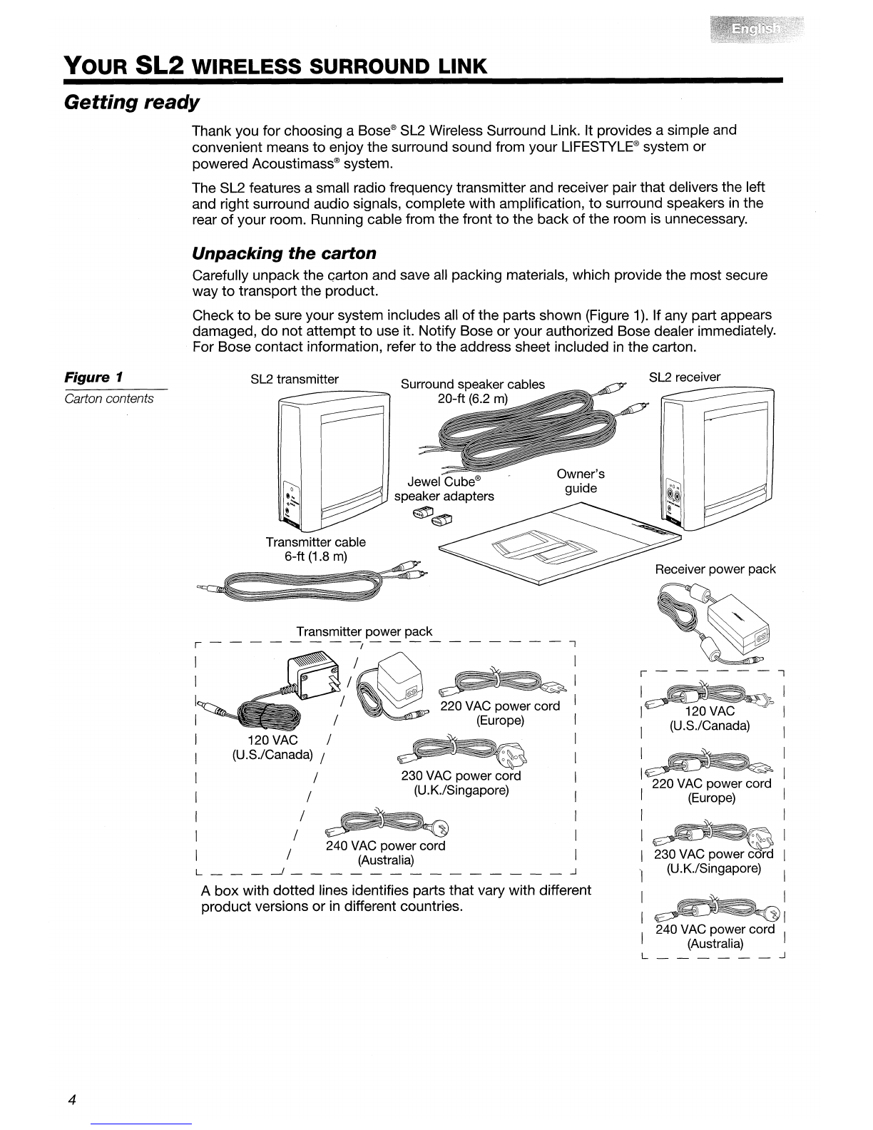
The product serial number is located on the bottom ofthe SL2 transmitter.
Serial number: _
Dealer name: _
Dealer phone: Purchase date: _
For future reference, it can be helpful to keep the sales slip and acopy
of
your product registration card together with
this guide.
3

YOUR
SL2 WIRELESS SURROUND LINK
Getting
ready
Thank you for choosing a
Bose®
SL2 Wireless Surround Link. It provides asimple and
convenient means
to
enjoy the surround sound from your
LIFESTYLE®
system or
powered Acoustimass® system.
The SL2 features asmall radio frequency transmitter and receiver pair that delivers the left
and right surround audio signals, complete with amplification,
to
surround speakers
in
the
rear
of
your room. Running cable from the front
to
the back
of
the room is unnecessary.
Unpacking the carton
Carefully unpack the Garton and save all packing materials, which provide the most secure
way
to
transport the product.
Check
to
be sure your system includes all
of
the parts shown (Figure
1).
If any part appears
damaged,
do
not attempt
to
use it. Notify Bose or your authorized Bose dealer immediately.
For Bose contact information, refer
to
the address sheet included
in
the carton.
Transmitter power pack
r-------,----------,
SL2 receiver
Receiver power pack
r-------,
I~I
I120
VAG
I
I(U.S.lGanada) I
I~I
I I
220
VAG
power cord
I(Europe) I
I I
I~I
I230
VAG
power cord I
"I
(U.K.lSingapore) I
:~:
I240
VAG
power cord I
(Australia)
L
~
Surround speaker cables
20-ft (6.2
m)
~:
220 VAG power cord I
(Europe) I
~:
230
VAG
power cord I
(U.K.lSingapore) I
I
I
I
SL2 transmitter
A
box
with dotted lines identifies parts that vary with different
product versions or
in
different countries.
Transmitter cable
6-ft (1.8
m)
~
~
~
240
VAG
power cord
(Australia)
L
~
~
Figure 1
Carton contents
4

Figure
2
Speaker switch
YOUR
SL2 WIRELESS SURROUND LINK
If you have not yet done so, now is agood time
to
find the serial number on the bottom
of
the
SL2 transmitter, then copy it
in
the space provided on "For your records" on page
3.
Setting
the
transmitter
for
your
system
If your speakers are part
of
an
Acoustimass® speaker system, you need
to
set the switch on
the bottom
of
the SL2 transmitter
to
Other (Figure
2).
Bottom
of
the
SL2 transmitter
Switch
For use
of
a
LIFESTYLE®
system with the SL2 Wireless Surround Link, the current default
switch setting is optimal. There is no need
to
change the setting.
J
Important
note:
Running the
AOAPTiQ®
audio calibration system, which is provided with
your
LIFESTYLEID
system, helps ensure the
most
accurate
sound
from
your
system. Be sure to use it
after the SL2
is
connected
and
your
surround speakers are
in
the final position.
Choosing
positions
for
your
SL2
transmitter
and
receiver
Radio frequency transmissions make this product easy
to
place. It is seldom necessary
to
point the SL2 transmitter at its receiver. This allows you
to
hide both from view if you like.
The SL2 transmitter, identified on the label,
is
also distinguished by asingle input jack
(see Figure 3
on
page
6).
The SL2 receiver, which is also labeled, has
two
output jacks.
1.
Place the SL2 transmitter within 61/2feet
(2
meters)
of
the Acoustimass® module.
Make sure it
is
within reach
of
an
AC (mains) outlet.
2.
Place the SL2 receiver at the same end
of
the room as your surround speakers.
It, too, should be within reach
of
an
AC (mains) outlet.
Position the transmitter/receiver pair:
•From 61/2feet
(2
meters)
to
30 feet
(9.2
meters) apart.
•Where the sides are unobstructed
to
allow for ventilation.
•Upright (neither upside down nor on aside) on the floor or other flat, stable surface.
J
Note:
If
you experience anyproblem with communications between the SL2 transmitter
and
receiver, positioning them within line
of
sight to each other
may
be
helpful. For further
suggestions on
how
to deal with such problems, refer to "Troubleshooting" on page
9.
5

YOUR
SL2 WIRELESS SURROUND LINK
Making
the
connections
Use the small power pack with the SL2 transmitter (Figure
3).
The large power pack is for use
with the SL2 receiver.
AC power jack
Before you plug either
of
the supplied power packs into the wall, first connect it to the
receiver power pack.
Different
power
supplies
Figure
3
Connecting
the
SL2
transmitter
Use the supplied transmitter cable
to
connect the SL2 transmitter
to
your Acoustimass®
module, as follows (Figure
4):
1.
Insert the single connector at one end
of
the cable into the input jack labeled
Acoustimass Module on the back
of
the SL2 transmitter.
2.
Connect the other end
of
the transmitter cable to jacks on the Acoustimass module.
•Insert the connector marked
RR
into the jack labeled Right Rear or Surround
R.
•Insert the connector marked
LR
into the jack labeled Left Rear or Surround
L.
3.
Connect the cable end
of
the transmitter power pack
to
the small jack labeled
DC
Power
on the back
of
the SL2 transmitter.
4.
Plug the transmitter power pack into anearby AC mains outlet.
Figure
4Acoustimass module
Transmitter
connections Status
LED
SL2 transmitter
Transmitter
power
pack
(12QV
shown)
When the power supply is plugged
in,
aStatus
LED
on the back
of
the transmitter blinks
green.
6

YOUR
SL2 WIRELESS SURROUND
LINK
Conne,cting
the
SL2
receiver
Use the supplied 20-ft (6.2-m) cables
to
connect the speakers
to
the SL2 receiver.
Or,
you
may prefer
to
use the longer surround speaker cables that came with your speakers.
J
Note:
To
use the SL2 supplied cables with Jewel
Cube®
speakers, first attach aJewel Cube
adapterto each cable as described
in
"To
adapt
the surround speaker cable for Jewel
Cube®
speakers" on page
8.
To
make
the
receiver
connections
1.
Insert the orange RCA connectors into jacks on the back
of
the SL2 receiver (Figure
5).
•Use the one marked
RR
in
the jack labeled
RR.
•Use the one marked
LR
in
the jack labeled
LR.
2.
Connect the wire ends
of
the cable
to
your surround speakers.
•Insert the connector marked Rinto the jack on the speakerthat is placed on the right.
•Insert the connector marked Linto the jack on the speaker that is placed on the left.
For details on how
to
set up and make connections
to
your surround speakers, refer
to
the owner's guide provided with them.
3.
Connect the cable end
of
the receiver power pack
to
the small jack labeled
DC
Power on
the back
of
the receiver.
4.
Plug the power cord into anearby AC (mains) outlet.
Figure
5
SL2 receiver
connection to
speakers
Surround sound speakers
e
e
Status
LED
SL2 receiver
Receiver
power pack
AC power
outlet
When this power supply is plugged in, the Status
LED
on the back
of
the SL2 receiver blinks
green. If both transmitter and receiver power supplies are connected and plugged in, the
Status
LEOs
on both the SL2 transmitter and receiver light asolid green
to
indicate they are
communicating with each other.
For
an
explanation
of
the other
LED
colors, refer
to
"What the Status
LEOs
indicate" on
page
8.
7

YOUR
SL2 WIRELESS SURROUND LINK
To
adapt
the
surround
speaker
cable
for
Jewel
Cube® speakers
Follow these steps before you connect the provided surround speaker cable
to
your Jewel
Cube®
speakers.
1.
Loosen the screws on the Jewel
Cube®
speaker adapter so you can insert the two-wire
ends into its terminals.
•Insert the plain wire (-) into the plain terminal.
•Insert the red-banded wire
(+)
into the red terminal.
2.
Tighten the screws (Figure
6).
Jewel Cube
speaker
Redban~"
Red
terminal
screw
Ada~~:
~
on~
Using this cable with the adapters attached, follow the steps
in
"To
make the receiver
connections" on page
7.
Be sure
to
match each adapter
to
the proper speaker, right or left.
Using the adapter
with aJewelCube
speaker
Figure 6
What
the
Status LEDs indicate
On
the rear
of
the SL2 transmitter and receiver, the color
of
the Status
LED
indicates how
each unit is functioning. The indicators include:
•Blinking green: the power pack
is
plugged
in
and the unit is searching for asignal.
•Solid green: the receiver and transmitter are communicating with each other.
•Solid orange:
in
sleep mode for low power use when there
is
no signal
to
communicate.
•Blinking red: the SL2 receiver
is
too hot, or there is aproblem with the surround speaker
cable connection between the SL2 receiver and the speakers.
For information on how to deal with ablinking red
LED,
see "Troubleshooting" on page
9.
8

YOUR
SL2 WIRELESS SURROUND LINK
Troubleshooting
Problem
What
to
do
Blinking red Status •Disconnect the unit from the AC power outlet.
LED
on either the •Remove any possible obstruction
to
ventilation and reposition the unit upright with
SL2 transmitter or clear space around the ventilation openings on each side. If the ventilation was
receiver obstructed, allow the unit afew minutes
to
cool before reconnecting it
to
the AC power
outlet.
•If it continues
to
blink red, check the cable connection between the SL2 receiver and
the surround speakers. Make sure the connections are secure and the cable wires are
not touching each other, which can cause ashort circuit. Refer
to
"Connecting the SL2
receiver" on page
7.
Reconnect the unit
to
the AC power outlet.
•If it continues
to
blink red, unplug the unit from the power outlet and contact
Bose®
Customer Service. Refer
to
the address list included
in
the SL2 carton.
No sound or •Make sure the audio source
is
playing and the program selected includes surround
intermittent sound sound audio.
•Check
to
be sure both the SL2 transmitter and receiver power packs are properly
plugged into functioning AC power outlets. Refer
to
"Making the connections" on
page
6.
•Make sure that cables are properly connected
to
the SL2 transmitter, the Acoustimass®
module, the SL2 receiver, and the surround speakers. The connectors must be
inserted securely
in
the jacks.
•Make sure the SL2 transmitter and receiver are no less than 61/2feet
(2
meters) and no
more than 30 feet
(9.2
meters) apart.
•Locate the small opening labeled Reset on the bottom
of
both the SL2 transmitter and
the SL2 receiver. Insert afine-pointed tool (like astraightened paper clip), into the small
opening on the transmitter and then, within 30 seconds, on the receiver.
•Move the receiver, the transmitter, or both so the transmission path between them
does not intersect with large metal objects
in
your
room·
or other obstructions (like a
fish tank full
of
water).
When the problem is resolved, the Status
LEOs
turn asolid green.
Interference with a•Increase the distance from each SL2 unit
to
the phone.
wireless (5.8GHz) •Press the channel button on the phone (if one is provided)
to
choose adifferent
phone channel for phone transmissions.
Contacting Customer Service
For additional help
in
solving problems, contact Bose Customer Service. Refer to the address
sheet included
in
the carton.
9

YOUR
SL2 WIRELESS SURROUND LINK
Technical Information
Power
supply rating
Transmitter:
u.s.:
120Vrv
60Hz 60mA
EU:
220-240Vrv
50Hz 60mA
Other:
240Vrv
50Hz 60mA
Receiver:
100-240Vrv
50/60Hz 2A
Output:
Transmitter: 8.2VDC 500mA
Receiver: 24VDC 3.5A
Ambient
operating
temperature
range
40°F
to
120°F
(4°C
to
49°C)
Frequency
band
5.8 GHz
Transmitter audio
input
level
Compatible with amplifiers rated up
to
200W per channel
(Use with amplifiers rated above 200W may cause damage
to
the SL2.)
RF
transmit
power
12 dBm maximum
Dimensions
of
each
unit
2"W
x
5"0
x5"H (5.2 cm x12.4 cm x12.4 cm)
Limited
Warranty information
For your benefit, we recommend that you record product serial numbers and other purchase
information on the form provided
in
"For your records" on page
3.
Also keep your proof
of
purchase with this owner's guide. If necessary, this information will allow us
to
better serve
your needs.
'To
send any correspondence regarding product information or Limited Warranty services,
refer
to
the address list included
in
the carton.
This Limited Warranty applies only
to
Bose®
products purchased
in
the United States,
Puerto Rico and Canada.
In
other countries, other warranties may apply. For information
about the Limited Warranty coverage elsewhere, please contact your Bose dealer.
Limited
Warranty
What
is
covered:
All parts defective
in
material and workmanship.
What is not covered:
Defects that have resulted from improper or unreasonable use or maintenance, accident,
excess moisture, insects, improper packing, lightning, power surges, or unauthorized
tampering, alteration, or modification are not covered.
10

YOUR
SL2 WIRELESS SURROUND
LINK
Limitation
on liability:
WHERE PERMITIED, THE PROVISIONS
OF
THIS LIMITED WARRANTY
ARE
IN
LIEU
OF
ANY OTHER WARRANTY, WHETHER EXPRESS
OR
IMPLIED, WRITTEN
OR
ORAL, INCLUD-
iNG ANY WARRANTY
OF
MERCHANTABILITY
OR
FITNESS FOR APARTICULAR PURPOSE.
Notwithstanding the above, where applicable, if you qualify as a"consumer" under the Mag-
nuson-Moss Warranty Act, then you may be entitled
to
any implied warranties allowed by law
for the period
of
the express Limited Warranty as set forth below. Some states do not allow
limitations on how long
an
implied Limited Warranty lasts, so the above limitation may not
apply
to
you.
For
how
long:
The
Bose®
Limited Warranty lasts one year from the purchase date for electronic products,
systems, and powered speaker components, accessories, and other products not listed here.
What
we
will
do:
We
will, at our sole option, repair or replace any defective parts within areasonable period
of
time and free
of
charge.
What
we
will
not
do:
Pay shipping or transportation charges from you to us.
What
you
must
do
to
obtain
Limited
Warranty
Service:
1. Return product with proof
of
purchase from
an
authorized Bose dealer directly to Bose
Corporation. If you elect
to
return the product directly
to
Bose Corporation, the following
procedures must be followed:
Contact Bose Corporation at 1-800-367-4008 for return authorization number, specific
return and shipping instructions, which will include but may not be limited to:
Properly packing the product
in
the original carton for shipping. If you need anew carton,
contact Bose Corporation for free packing material and box
..
Cartons not bearing areturn
authorization number will be refused.
2.
Return product with proof of purchase from
an
authorized Bose dealer
to
aBose Service
Agency.
Exclusive remedy:
Subject
to
the limitations below, this Limited Warranty is fully transferable provided that the
current owner furnishes the originarproof
of
purchase from
an
authorized Bose dealer. THE
MAXIMUM LIABILITY
OF
BOSE SHALL NOT EXCEED THE ACTUAL PURCHASE PRICE
PAID
BY YOU
FOR
THE PRODUCT.
IN
NO EVENT SHALL BOSE
BE
LIABLE
FOR
SPECIAL,
INCIDENTAL, CONSEQUENTIAL
OR
INDIRECT DAMAGES. Some places do not allow limita-
tions on the exclusion or limitation
of
relief, special, incidental, consequential or indirect dam-
ages, or the limitation
of
liability
to
·specified amounts, so the above limitations or exclusions
may not apply
to
you.
Other
conditions:
This Limited Warranty gives you specific legal rights, and you may also have other rights that
vary from country
to
country or state
to
state. This
Limited
Warranty
is
void
if
the
label
bearing
the
serial
number
has been
removed
or
defaced
or
if
the
product
is
not
pur-
chased
from
an authorized reseller. .
Your Limited Warranty Rights are not diminished if you
do
not complete and return the
product registration card. Bose Corporation thanks you for your recent Bose product
purchase.
We
hope it will give you years
of
satisfaction.
11

--B05'~
Bettersound
through
research®
1111111111111111111111111111111111111111
291706-001
©2006 Bose Corporation, The Mountain,
Framingham,
MA
01701-9168 USA
AM291706
Rev.OO
CCM-002607

USA
Bose Corporation, The Mountain
Framingham, MA 01701-9168
1-800-367-4008 or 508-766-1900
Phone hours -
ET
(Eastern Time):
Weekdays 8:30 a.m. to 8p.m.
Saturdays 9a.m.
to
3p.m.
owners.bose.com
Canada
Bose Ltd., 1-35 East Beaver Creek Road
Richmond Hill, Ontario L4B 1B3
1-800-465-2673
Phone hours -
ET
(Eastern Time):
Weekdays 9a.m.
to
5p.m.
www.bose.ca
Australia
Bose Pty Limited, Unit 3/2 Holker Street
Newington NSW 2127
TEL 612 8737 9999
FAX
·612
8737 9924
Be
IgiquelBeIgie
Bose
N.V.,
Limesweg 2
B-3700 Tongeren
TEL 012-390800
FAX
012-390840
China
Bose Electronics (Shanghai) Ltd
2203-2305
22F,
West Gate Tower
1038 West Nanjing Road
MeiLongzhen Plaza
Shanghai 200041
Peoples Republic
of
China
TEL 86-22-62713000 ext 162
FAX
86-21-62713008
Danmark
Bose A/S, Industrivej 7
2605 Br0ndby
TEL 04343-7777
FAX
04343-7818
Deutschland
Bose GmbH, Max-Planck-StraBe 36d
D-61381 Friedrichsdorf
TEL 06172-71040
FAX
06172-710419
www.bose.de
France
Bose S.A.S.,
6,
Rue
Saint Vincent
78100 Saint Germain
en
Laye
TEL 01-30616363
FAX
01-30616388
India
Bose Corporation India Private Limited
4th Floor,
Shriram Bhartiya Kala Kendra,
1Copernicus Marg
New Delhi, India 100
001
TEL
+91
11
2307 3825 /3826 /3827
FAX
+91
11
2307 3823
Ireland
Bose
GP
Castleblayney Road
Carrickmacross, Co Monaghan
TEL
(042)
9671500
FAX
(042) 9671501
www.bose.ie
1111111111111111111111111111111111
289347-001
Italia
Bose S.p.A., Via della Magliana 876
00148 Roma
TEL 06-65670802
FAX
06-65680167
www.bose.it
Japan
Bose K.K.
Shibuya YT Building
28-3 Maruyama-cho
Shibuya-ku, Tokyo 150-0044
TEL +81-3-5489-0955
FAX
+81-3-5489-1041
www.bose.co.jp
Mexico
Bose de Mexico
S.
de R.L. de
C.V.
Paseo de las Palmas #405
Despacho 204
Lomas de Chapultepec
C.R 11000, Mexico
D.F.,
Mexico
TEL +52
(55)
52
02
35 45
TEL +52
(55)
52
02
41
95
FAX
+52
(55)
52
02
37 28
Nederland
Bose
B.V.,
Nijverheidstraat 8
1135
GE
Edam
TEL 0299-390111
FAX
0299-390109
Norge
Bose A/S, Lerkeveien 58
2209 Kongsvinger
TEL
62
82
1560
FAX
62
82
1569
Osterreich
Bose Ges.m.b.H., Vienna Business Park
Wienerbergstrasse 7(10.0G)
A-11 00 Vienna
TEL 01-60404340
FAX
01-604043423
www.bose.at
Schweiz
Bose AG, Hauptstrasse 134
4450 Sissach
TEL 061-9757733
FAX
061-9757744
www.bose.ch
Sverige
Bose A/S, Johannefredsgatan 4
S-43153 Molndal
TEL 031-878850
FAX
031-274891
United
Kingdom
Bose Limited
1Ambley Green
Gillingham Business Park
Gillingham, Kent ME8 ONJ
TEL 0870-741-4500
FAX
0870-741-4545
www.bose.co.uk
World
Wide
Web
www.bose.com
owners.bose.com
-BUS~
Better
sound
through research®
©2005 Bose Corporation, The Mountain, Framingham, MA 01701-9168 USA
289347 AM Rev.02 CCM-040001
Table of contents
Popular Transmitter manuals by other brands

Emerson
Emerson Rosemount FCL-01 Reference manual

HITROL
HITROL HT-100PT instruction manual

Altinex
Altinex Computer/Component Video+ Audio Dual Twisted Pair Transmitter... user guide

Decade
Decade MS-100 series instruction manual

RKI Instruments
RKI Instruments 65-2649XLCH44SS Operator's manual

Lectronics
Lectronics HM/E01 instruction manual

Decko
Decko 24125 user manual

Emerson
Emerson Rosemount 5408 Reference manual

Distech Controls
Distech Controls HS-OT 2X Series Commissioning and hardware installation manual

Absolute Process Instruments
Absolute Process Instruments API 4400 G quick start guide

Vaisala
Vaisala DRYCAP DMT340 SERIES user guide

Emerson
Emerson Rosemount 5408 Reference manual