BOSER Technology HS-6237 User manual

HS-6237/6637
BX Celeron
™
/ Coppermine
™
VGA LAN
•Half Size•All in one•CRT/Panel•LAN•
•WDT•DOC•USB•IrDA•CTA•PC/104•
•PISA/ISA Bus Industrial Single Board computer•
HS-6237V/6637V
BX Celeron
™
/ Coppermine
™
VGA
•Half Size•All in one•CRT/Panel•
•WDT•DOC•USB•IrDA•CTA•PC/104•
•PISA/ISA Bus Industrial Single Board computer•

Copyrights
This manual is copyrighted and all rights are reserved. Any kind of reproduction in
whole or in part without prior written consent from the manufacturer is prohibited.
In general, the manufacturer will not be liable for any direct, indirect, special,
incidental or consequential damages arising from the use of inability to use the
product or documentation, even if advised of the possibility of such damages.
Themanufacturerreserves the right to change the contents of this manual without
prior notice in order to improve the function design, performance, quality and
reliability.Theauthorassumesnoresponsibilityforanyerrorsoromissions,which
may appear in this manual, nor does it make a commitment to update the
information contained herein.
Trademarks
BOSER is a registered trademark of BOSER Technology Co., Ltd.
ISB is a registered trademark of BOSER Technology Co., Ltd.
Intel is a registered trademark of Intel Corporation.
AWARD is a registered trademark of AWARD International Inc.
All other trademarks, products and or product's name mentioned herein are
mentioned for identification purposes only, and may be trademarks and/or
registered trademarks of their respective companies or owners.
© Copyright 2000
All Rights Reserved.
User Manual edition 2.3, Aug.24 2001

Contents?i
Contents
HS-6237/6637.........................................................................................................1
HS-6237V/6637V...................................................................................................1
GENERAL INFORMATION ..................................................................3
1.1 MAJOR FEATURES ........................................................................4
1.2 SPECIFICATIONS............................................................................5
1.3 DELIVERY PACKAGE......................................................................7
HARDWARE INSTALLATION..............................................................8
2.1 CAUTION OF STATIC ELECTRICITY .....................................................8
2.2 CAUTION ON UNPACKING AND BEFORE INSTALLATION............................9
2.3 HS-6237/HS-6637’S LAYOUT ...................................................... 10
2.4 QUICK LISTING OF JUMPERS ........................................................... 11
2.5 QUICK LISTING OF CONNECTORS..................................................... 12
2.6 JUMPER SETTING DESCRIPTION ....................................................... 13
2.7 SETTING THE BUS-CLOCK FREQUENCY............................................. 14
2.8 SETTING THE RTC CONFIGURATION................................................. 14
2.9 SYSTEM MEMORY DRAM............................................................. 14
2.10 WATCH-DOG TIMER................................................................... 15
2.11DISKONCHIP?ADDRESS SETTING................................................. 17
CONNECTION.................................................................................. 18
3.1 POWER AND FAN CONNECTORS .................................................... 18
3.2 IDE'S LED, KEYLOCK AND RESET BUTTON ...................................... 19
3.3 EXTERNAL SPEAKER.................................................................... 20
3.4 PCI E-IDE DRIVE CONNECTOR...................................................... 21
3.5PARALLEL CONNECTOR................................................................ 22
3.6 THE FLOPPY DISK DRIVE CONNECTOR.............................................. 23
3.7 SERIAL PORTS CONNECTORS ........................................................ 24
3.8 KEYBOARD CONNECTORS............................................................. 25
3.9 PS/2 6PIN MINI DIN MOUSE CONNECTOR.......................................... 25
3.10 VGA CONTROLLER ................................................................... 26
3.11 IR CONNECTOR......................................................................... 29
3.12 USB CONNECTOR..................................................................... 29
3.13 LAN INTERFACE CONNECTOR....................................................... 30
3.14 PC/104 BUS CONNECTOR .......................................................... 31

ii ?Contents
AWARD BIOS SETUP ...................................................................... 33
4.1 MAIN MENU............................................................................... 34
4.2 STANDARD CMOS SETUP............................................................ 35
4.3 BIOS FEATURES SETUP............................................................... 36
4.4 CHIPSET FEATURES SETUP............................................................ 37
4.5 INTEGRATED PERIPHERALS............................................................ 38
4.6 POWER MANAGEMENT SETUP........................................................ 40
4.7 PNP/PCI CONFIGURATION SETUP................................................... 41
SOFTWARE UTILITIES .................................................................... 42
5.1 VGA DRIVER INSTALL FOR WIN95 & WIN98................................... 43
5.2 VGA DRIVER INSTALL FOR WIN NT4.0........................................... 46
5.3 LANDRIVER INSTALL FOR WIN95 & WIN98.................................... 50
5.4 LANDRIVER INSTALL FOR WIN NT4.0............................................ 53

3
Chapter-1
General Information
TheHS-6237/HS-6637isa100MHz BusIntel®BX chipset design PISA/ISA
Bus Celeron™/Coppermine™(Coppermine™ only for Ver2.1 PCB)
Industrial Single Board Computer with features combine together to make
itanidealall-in-one industrial single board computer, enhanced I/O effects
with LAN and CRT/Panel interface.
With on board DMA33 of mode 4 to IDE drive interface architecture, the
HS-6237/HS-6637 supports with maximum 33.3 MB/sec in data transfer
rating to one IDE drive connection. Design with Intel®82443 BX core logic
chipsetsupportsallseriesCeleron™/Coppermine™ operating at 266MHz
to800MHz.The on board 69000 CRT/Panel display controller supports up
to 1280x1024x256 colors display resolution. And it also provides one
internal 50pin connector for various type of the Panel connection.
The advanced PISA bus add-on connection of HS-6237 allows user could
easilyobtainboth ISA's 16bitandPCI's32bit full setsignalsfroma half size
PISA slot for suitable plug into any size system with 8/16/32bit ISA and-or
PCI slots operating. The HS-6237/HS-6637 provides with two DIMM
sockets support up to 512 MB of main system memory.
A single Flash chip holds the system BIOS, and you can easy update the
Flash BIOS by the Utility Update. Advanced USB and IR ports also provide
for faster and easily in data transmission. You can also use the DOS
version of the "DiskOnChip?" socket by issuing commands from the DOS
prompt without the necessity of other software supports up to 144MB.
The HS-6237/HS-6637 features include one Intel®82558 10/100 Based
LANdesignonboard.With one external RJ45 connector provides aneasily
for user’s LAN application.
If a non-expect program cause halts, the on board Watch-Dog Timer will
automaticallyresettheCPUorgenerateaninterrupt.TheWatch-Dog Timer
isdesignedwithhardwareonlyanddoesn’tneedanyarithmeticalfunctions
of a real-time clock chip. This ensures the reliability in an unmanned or

4
standalone system.
1.1 Major Features
?? PISA Bus (HS-6237) and ISA Bus (HS-6637) supported
?? Socket 370 for Intel®CeleronTM/CoppermineTM 266~800MHz CPU
?? Two DIMM sockets provides up to 512MB
?? Fast PCI DMA33 controller supports two IDE disk drives
?? PnP I/O address & IRQ selection
?? Two RS-232 serial ports include 16C550 UART with 16byte FIFO
?? One enhanced bi-directional parallel port supports SPP/ECP/EPP
?? On board PS/2 Keyboard and PS/2 Mouse connector
?? On board Winbond W83977 super I/O chipset
?? On board 69000 CRT/Panel display controller
?? On board Intel®82558 10/100 Based LAN
?? DiskOnChip memory size up to 144MB
?? PC/104 Bus connector
?? CPU Temperature Alarm support
*It will be a Warning “beep” come out if the CPU’s temperature reached 60
℃. And it will stop as the CPU’s temperature going down below 60℃
again.

5
1.2 Specifications
??CPU:Socket 370 for Intel®CeleronTM/CoppermineTM 266~800MHz
CPU
??Bus Interface:PISA Bus (HS-6237) / ISA Bus (HS-6637)
??Memory:Two DIMM sockets provides up to 512MB
??Chipset:Intel®82443BX
??I/O Chipset:Winbond W83977
??VGA:69000 with 2MB memory support CRT/Panel display up to
1280x1024x256colors
??IDE:Two IDE disk drives support DMA33 transfer rate up to 33MB/sec
??Floppy:Support up to two floppy disk drives
??Parallel Port:Support SPP/ECP/EPP
??LAN:Intel®82558 10/100 Based LAN
??Serial Port:Two RS-232 serial ports include 16C550 UART with
16byte FIFO
??PC/104:PC/104 connector for 16bit ISA Bus
??IR:One IrDA TX/RX header
??USB:Support two USB ports
??Keyboard:PS/2 6pin Mini Din or 5pin connector
??Mouse:PS/2 6pin Mini Din
??DiskOnChip:Socket for DiskOnChip and memory size up to 144MB
??BIOS:Award Y2K PnP Flash BIOS

6
??Watch-Dog Timer:Set 1, 2, 10, 20, 110, 220 seconds activity trigger
with Reset or NMI
??CMOS:DS12C887 or equivalent device
??DMA Channels:7
??Interrupt Levels:15
??Extra Power:One 10pin +5V/+12V connector
??Maximum Power Consumption:+5V@5A、+12V@120mA
??Operating Temperature:0~60°C
??CPU Temperature Alarm:Beeping alarm when CPU’s temperature
over heating limited
??Board Size:7.3”(L) x 4.8”(W)

7
1.3 Delivery Package
The delivery package of HS-6237/HS-6637 includes all following
items:
?? One HS-6237/HS6637 Industrial Single Board Computer
?? One Printer Ports Bracketed Flat Cable
?? One COM port Bracketed Flat Cable
?? One IDE port Flat Cable
?? One FDD port Flat Cable
?? One PS/2 to Standard type Keyboard Transfer Cable
?? Utility CD-ROM
?? User’s Manual
Please contact with your dealer if any of these items are missing or
damaged when purchasing. And please keep all parts of the delivery
package with packing materials in case of you want to ship or store
the product in feature.

8
Chapter-2
Hardware Installation
This chapter provides the information on how to install the hardware of
HS-6237/6637. At first, please follow up sections 1.3, 2.1 and 2.2 in
check the delivery package and carefully unpacking. Following after,
the jumpers setting of switch, watchdog timer and the DiskOnChip?
address selection etc.
2.1 Caution of Static Electricity
The HS-6237/6637 has been well package with an anti-static bag in
protect its sensitive computer components and circuitry from the
damage of static electric discharge.
Note: DO NOT TOUCH THE BOARD OR ANY OTHER SENSITIVE
COMPONENTS WITHOUT ALL NECESSARY ANTI-STATIC
PROTECTION.
You should follow the steps as following to protect the board in against
the static electric discharge whenever you handle the board:
1. Please use a grounding wrist strap on whoever needs to handle the
HS-6237/6637. Well clip the ALLIGATOR clip of the strap to the end
of the shielded wire lead from a grounded object. Please put on and
connect the strap before handle the HS-6237/6637 for harmlessly
discharge any static electricity through the strap.
2. Please use anti-static pad for put any components or parts or tools
on the pad whenever you work on them outside the computer. You
may also in use the anti-static bag instead the pad. Please ask from
your local supplier in help up your necessary parts on anti-static
requirement.

9
2.2 Caution on Unpacking and Before Installation
First of all, please follow with all necessary steps of section 2.1 in
protection the HS-6237/6637 from electricity discharge. With refer to
section 1.3, please check the delivery package again with following
steps:
1.Unpacking the HS-6237/6637, keep well storage of all packing
material, manual and diskette etc. if has.
2.Is there any components lose or drop from the board? DO NOT
INSTALL IF HAPPENED.
3.Is there any visual damaged of the board? DO NOT INSTALL IF
HAPPENED.
4.Well check from your optional parts (i.e. CPU, SRAM, DRAM,
ROM-Disk etc.) for completed setting all necessary jumpers setting
to jumper pin-set and CMOS setup correctly. Please also reference
to all information of jumpers setting in this manual.
5.Well check from your external devices (i.e. Add-On-Card, Driver
Type etc.) for completed add-in or connection and CMOS setup
correctly. Please also reference to all information of connector
connection in this manual.
6.Please keep all necessary manual and diskette in a good condition
for your necessary re-installation if you change your Operating
System or whatever needs.

10
2.3 HS-6237/HS-6637’s Layout

11
2.4 Quick Listing of Jumpers
JP1 BUS CLOCK FREQUENCY SETTING.....................................P.14
JP2 VGA ENABLE / DISABLE SELECT .....................................P.26
JP4 RESET ........................................................................P.19
JP5 BUS CLOCK FREQUENCY SETTING.....................................P.14
JP6 CLEAR CMOS .............................................................P.14
JP7 WATCH-DOG TIMER ACTIVE TYPE SETTING..........................P.15
JP8 PANEL VOLTAGE SELECT................................................P.27
JP9(1-4) DISKONCHIP?ADDRESS SELECT......................................P.17
JP9(5-10) TIME OF WATCH-DOG SELECT .........................................P.15
JP10 USB CONNECTOR .........................................................P.29
JP11 LAN ENABLE / DISABLE SELECT ......................................P.30
JP12 CPU TEMPERATURE ALARM ENABLE / DISABLE SELECT

12
2.5 Quick Listing of Connectors
CN1 PRIMARY IDE CONNECTOR.............................................P.21
CN2 3PIN FAN POWER CONNECTOR .......................................P.18
CN3 IDE LED....................................................................P.19
CN4 SPEAKER....................................................................P.20
CN5 5PIN POWER CONNECTOR ...........................................P.18
CN6 POWER LED & KEYLOCK ..............................................P.19
CN7 DIMM 1.....................................................................P.14
CN8 DIMM 2.....................................................................P.14
CN9 FDD CONNECTOR.......................................................P.23
CN10 PC/104 64PIN CONNECTOR ............................................P.31
CN11 PC/104 40PIN CONNECTOR.............................................P.31
CN12 PARALLEL CONNECTOR..................................................P.22
CN13 IRDA..........................................................................P.29
CN14 COM1 CONNECTOR (5X2 HEADER)...................................P.24
CN15 5PIN POWER CONNECTOR ...............................................P.18
CN16 50PIN PANEL CONNECTOR...............................................P.26
CN17 5PIN KEYBOARD CONNECTOR ..........................................P.25
CN18 RJ45 CONNECTOR........................................................P.30
CN19 PS/2 6PIN MINI DIN MOUSE CONNECTOR............................P.25
CN20 15PIN CRT CONNECTOR (DB15) ......................................P.26
CN21 PS/2 6PIN MINI DIN KEYBOARD CONNECTOR.......................P.25
CN22 COM2 CONNECTOR (5X2 HEADER)...................................P.24
CN23 COM1 CONNECTOR (DB9).............................................P.24
CN24 COM2 CONNECTOR (DB9).............................................P.24
13
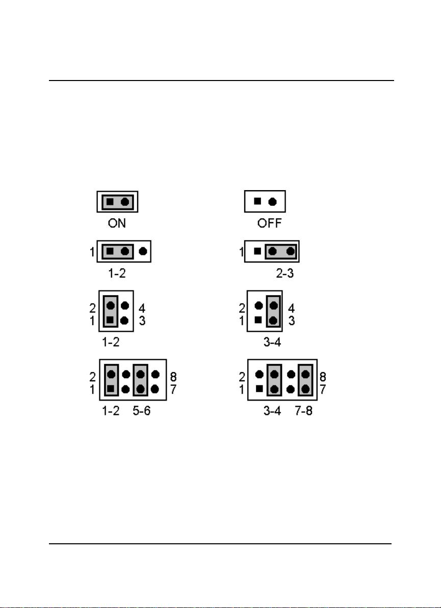
2.6 Jumper Setting Description
A jumper pin set isON as a shorted circuit with a plastic cap inserted
over two pins. A jumper pin-set is OFF as a open circuit with a plastic
cap inserted over one or no pin(s) between pins. The below figure 2.2
shows the examples of different jumper pin-set setting as ON or OFF
in this manual.
Figure 2.2
All jumper pin set already has its default setting with the plastic cap
inserted as ON, or without the plastic cap inserted as OFF. The
default setting may reference in this manual with a " * " symbol in front
of the selected item.
14
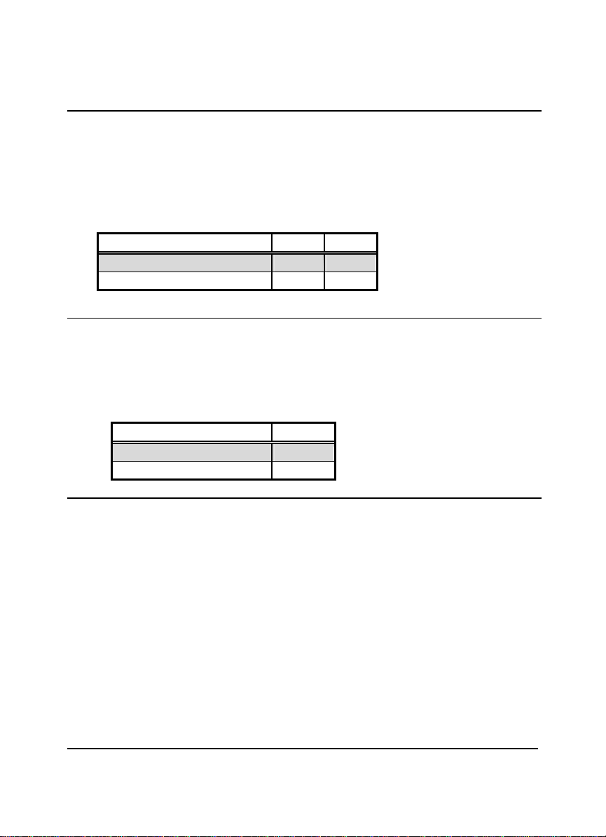
2.7 Setting the Bus Clock Frequency
The HS-6237/HS-6637 provides all necessary by jumper setting in
using Bus Clock frequency as the system bus clocking with JP1 and
JP5 setting as following:
?? JP1, JP5:Bus Clock Frequency Setting
Bus Clock Frequency JP1 JP5
*66MHz ON ON
100MHz OFF
OFF
2.8 Setting the RTC Configuration
The HS-6237/HS-6637 provides a setting for the selection of the RTC
Clear Jumper by JP6 setting as following:
?? JP6:CMOS Clear
CMOS Clear Jumper
JP6
Normal * OFF
Clear CMOS ON
2.9 System Memory DRAM
The HS-6237/HS-6637 provides a wide SDRAM memory by two DIMM
sockets (DIMM1, DIMM2) request the access time should meet
PC100 standard. The maximum capacity of the on board memory is
512MBytes.
15
2.10 Watch-Dog Timer
There are three access cycles of Watch-Dog Timer as Enable,
Refresh and Disable. The Enable cycle should proceed by READ
PORT 443H. The Disable cycle should proceed by READ PORT
045H. A continue Enable cycle after a first Enable cycle means
Refresh.
Once ifthe Enable cycle activity, a Refresh cycle is request before the
time-out period for restart counting the WDT's period. Otherwise, it will
assume that the program operation is abnormal when the time
counting over the period preset of WDT. A System Reset signal to
start again or a NMI cycle to the CPU comes if over.
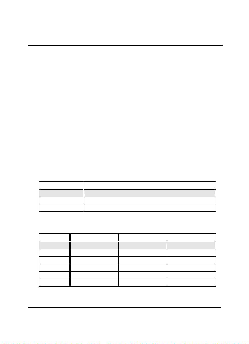
The JP7 is using for select the active function of Watch-Dog Timer in
disable the Watch-Dog Timer, or presetting the Watch-Dog Timer
activity at the reset trigger, or presetting the Watch-Dog Timer activity
at the NMI trigger.
?? JP7 : Watch-Dog Timer Active Type Setting
JP7 Description
*2-3System Reset
1-2Active NMI
OFF Disable Watch-Dog Timer
?? JP9(5-10) : WDT Time -Out Period
Period 5-67-89-10
*1 sec ON ON ON
2 sec OFF ON ON
10 sec ON OFF ON
20 sec
OFF OFF ON
110 sec
ON ON OFF
220 sec
OFF ON OFF

16
The Watch-Dog Timer is disabled after the system Power-On. The
Watch-Dog Timer can be enabled by a Enable cycle with reading the
control port (443H), a Refresh cycle with reading the control port
(443H) and a Disable cycle by reading the Watch-Dog Timer disable
control port (045H). After a Enable cycle of WDT, user must
constantly proceed a Refresh cycle to WDT before its period setting
comes ending of every 1, 2, 10, 20, 110 or 220 seconds which
pre-setting by JP4. If the Refresh cycle does not active before WDT
period cycle, the on board WDT architecture will issue a Reset or NMI
cycle to the system.
The Watch-Dog Timer is controlled by two I/O ports.
443H I/O Read The Enable cycle.
443H I/O Read The Refresh cycle.
045H I/O Read The Disable cycle.
The following sample programs showing how to Enable, Disable and
Refresh the Watch-Dog Timer:
WDT_EN_RF EQU 0443H
WDT_DIS EQU 0045H
WT_Enable PUSH AX ; keep AX DX
PUSH DX
MOV DX,WDT_EN_RF ; enable the WDT
IN AL,DX
POP DX ; get back AX, DX
POP AX
RET
WT_Rresh PUSH AX ; keep AX, DX
PUSH DX
MOV DX,WDT_ET_RF ; refresh the WDT
IN AL,DX
POP DX ; get back AX, DX
POP AX
RET
WT_DISABLE PUSH AX
PUSH DX
MOV DX,WDT_DIS ; disable the WDT
IN AL,DX
POP DX ; get back AX, DX
POP AX
RET

17
2.11 DiskOnChip?Address Setting
The HS-6237/HS-6637 provides a U9 socket for install the
DiskOnChip?module.
A JP9(1-4) may select the starting memory address of the
DiskOnChip?(D.O.C.) for avoid the mapping area with any other
memory devices. If you have another extra memory devices in the
system with the same memory, neither the HS-6237/HS-6637 nor the
extra memory devices will function normally. Please setting both at
different memory address mapping.
?? JP9(1-4) : DiskOnChip?Address
Memory Address Mapping
1-23-4
*D000 ON ON
D800 OFF ON
E000 ON OFF
*) : default setting
The D.O.C. function allows the system in using without FDD nor HDD.
The D.O.C. may formatting as driver C: or driver A: User may also
easily uses the DOS's commands such as FORMAT, SYS, COPY,
XCOPY, DISCOPY and DISKCOMP etc. This is means that the
D.O.C. may uses as driver-A if the system without FDD-A for ambient
application. Please contact with your supplier for different size D.O.C.
module.

18
Chapter-3
Connection
This chapter gives all necessary information of the peripheral's
connections, switches and indicators.
3.1 Power and FAN Connectors
The HS-6237/HS-6637 provides one 5pin DC-Power connector as
following CN15 pin information. And also provides one 3pin FAN out
connector as following CN2 pin information.
?? CN5 : 5pin Power Connector
PIN NO. Description PIN NO. Description
1VCC 2GND
3GND 4+12V
5-12V
?? CN2 : 3pin FAN Power Connector
PIN NO. Description PIN NO. Description
1GND 2VCC
3N/C
?? CN15 : 5pin Power Connector
PIN NO. Description PIN NO. Description
1VCC 2GND
3GND 4VCC
5VCC
This manual suits for next models
3
Table of contents
Other BOSER Technology Desktop manuals


