Boss Water Systems 021-4PC Installation and maintenance instructions
Boss Water Systems
Australia
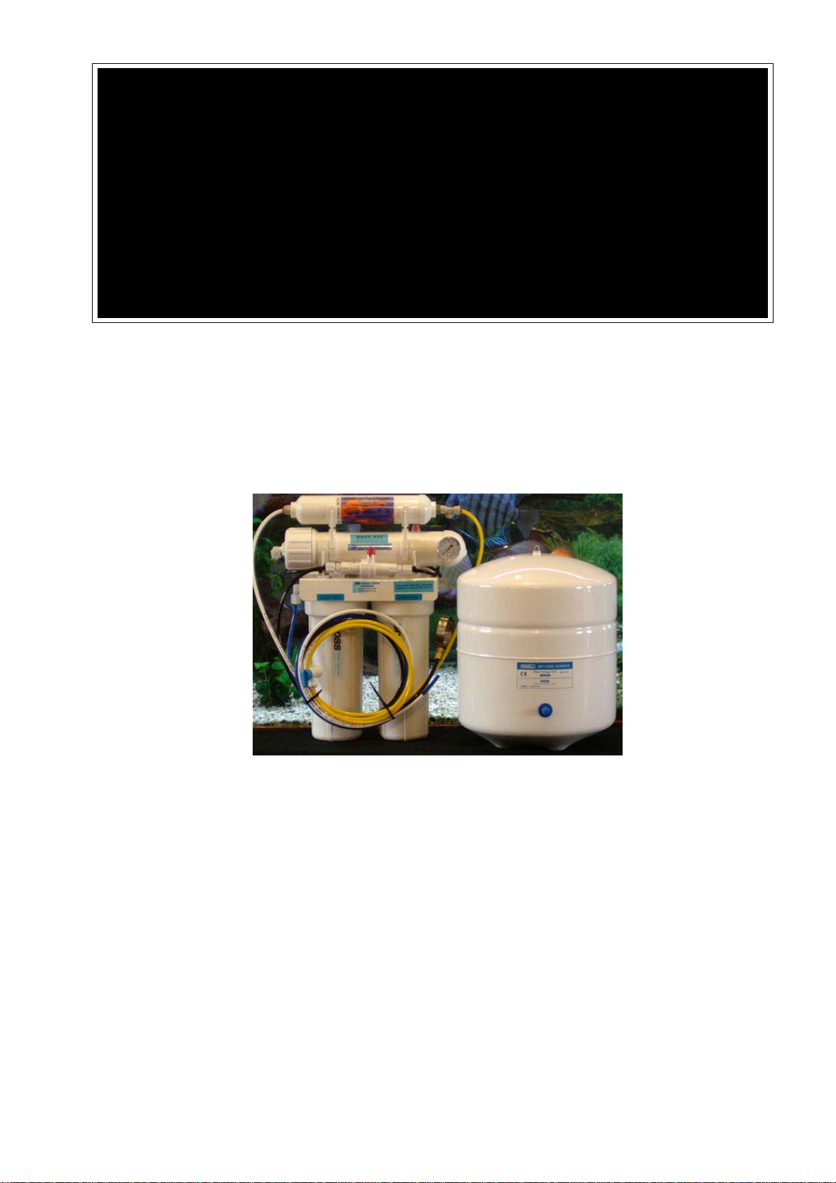
Reverse Osmosis System
Model – 021-4PC
Congratulations on your purchase of the
most advanced water purifier system
available!
Installation and Service Guide short web version,
this is not the instruction manual you will receive
with your purchase of a PSI-021-4PC but a shortened
version that is available on our web site, it is a
shorter version due to other suppliers likely to copy
this instruction manual as their own.
This system is designed to also remove ammonia which a normal reverse osmosis
system can’t do as the ammonia is introduced into the water as a gas not a liquid
REVERSE OSMOSIS WATER PURIFIERS
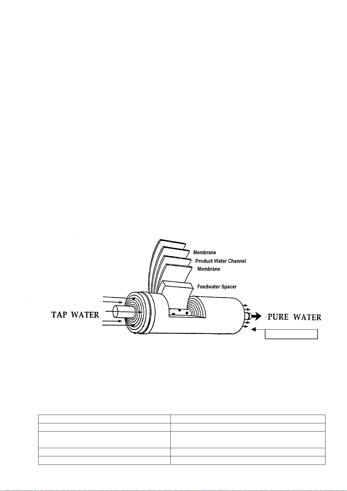
Of all the water purifier system types on the market by far the most superior is the reverse
osmosis process.
Reverse osmosis works by forcing water through a membrane, if the water molecule is
small enough it will pass across the membrane material and into the product line (pure
water). A water molecule is 2 parts hydrogen and 1 part oxygen (H2O) but if a molecule
had extra atoms attached the molecule is larger and won’t pass through the membrane
and is rejected, the contaminated molecule then goes into the waste line and is ejected
from the system.
The term “waste water” is not a kind way of describing the contaminated (waste) water
that is rejected by the reverse osmosis as it is water that is contaminated in some way and
not simply waste as such, the reverse osmosis process is a selection process, if the water
molecule is pure it will pass into the pure water part, anything else is rejected.
The reverse osmosis process is the best water purity of any type of process and is similar
to Distillation but distilled water is almost devoid of oxygen and tastes flat and dead,
reverse osmosis water process actually adds oxygen to the water resulting in extremely
pure sweet tasting water with almost all the poisons and impurities removed.
Waste Water
The PSI-021-4PC is designed for simple installation and operation and is well within the
abilities of a home handyman to maintain, the filters should be changed at the
recommended service intervals to maintain continual un-troubled service life.
Operating parameters
System Pressure 300 to 600 kpa (40 to 87 psi)
PH range 3.0 to 11.0
Maximum Supply TDS level (low waste
units) 500 mg/L = 500 ppm TDS
Temperature 2 to 40 degrees
Turbidity <1.0 Net Turbidity (NTU)

Caution
This Reverse Osmosis system is designed for operation on microbiologically safe water
which is usually Chlorinated mains water supplies, this system is not suitable for
installation on Un-Chlorinated water supplies, contact your selling agent to have a UV
steriliser added for microbiologically unsafe water such as Tank, Dam or Bore water.
Sediment Filter
Stage 1
Reverse Osmosis
Membrane Stage 3
Pressurised Storage
Tank
Pressure gauge to read
p
ressure being applied to
the membrane
Membrane Flushing
Valve/ Flow Restrictor
Carbon Post Filter
stage 4
Chloramine Carbon
Filter Stage 2
Stage 1 Sediment pre-filter, this filter is a 1 micron polyspun sediment filter cartridge
for mechanical removal of Grit, dust, Rust, mud, algae ect. This cartridge is
normally replaced every 12 months but if dirty mains water is encounted more
frequent change may be required.
Stage 2 Carbon pre-filter, this filter is a high grade chloramine carbon cartridge to
protect the membrane from chlorine and ammonia which can damage a TFC
(thin film composite) membrane, this carbon cartridge will also assist the
membrane by removing THMs, TCEs, pesticides and other organic pollutants.
This cartridge is usually changed every 12 months unless very dirty from the
mains supply is encountered or very heavy usage.

Stage 3 This is the membrane which is the main filter in a reverse osmosis system, pore
size is less than 0.0005 micron, the membrane is a thin film composite, NSF stand
42, 53 and 58, normal replacement is usually between 3 to 5 years.
Stage 4 This is the carbon polishing post filter which provides final filtration to
provide superb tasting clean water. Normal replacement is 12 months.
Installation
Select a suitable location avoiding locations where the system could come into contact
with things like hot water pipes, also consider ease of maintenance.
Check where the faucet (tap) will be installed looking at things like possible damage to
pipes and electrical wires when drilling, choose a location that will be the most
convenient for use.
Choose a location for the storage tank, the tank can be more remote than the main filter
system, a back corner cupboard is often used, the tank tube line is 1.8 metres, try
to have as short a tube to the tank and faucet as practicable because the shorter
the tube the faster the flow will be.
All tube is colour coded for installation ease
Blue tube connects from the mains supply to the entry point of the unit.
Yellow tube connects the main filter unit to the storage tank.
The black line connects the main filter unit for waste to the sink drain, this waste
line can be run outside to be collected for use in the garden.
The white line connects the main filter unit to the faucet (tap)
The mains connection best suited to your installation will have been selected at the time
of ordering, separate instructions are supplied with the mains connection kit, use
the supplied plumbers thread tape on all threaded joints, connect to cold water
mains supply only.
Faucet Installation
The RO water faucet may be installed on any flat surface at up to 50 mm [2”] in
diameter. Check the underside of the location for interference.

Determine desired location for the faucet on your sink surface.
A. Place a piece of masking tape or duct tape on location where the hole is to be
drilled. Mark the centre of the hole on the tape.
B. Using a variable speed drill on the slowest speed, drill a 1/8” (3 mm) pilot
hole at the centre of the desired location.
C. Enlarge the hole to ¼” (6 mm). Keep the drill speed on the slowest speed.
D. Enlarge the hole to 7/16th to ½” (11 to 13 mm) Keep the drill speed on the
slowest speed.
E. Pass the Escutcheon plate (chrome washer) and large black washer over the
threaded mounting tube at the base of the faucet.
F. From top of sink, slide the threaded mounting tube through the hole drilled
in the sink. Align the faucet body.
G. From under the sink, slide the smaller rubber washer on the threaded part of
the faucet first, then the plastic washer, locking washer and then the thin
threaded nut, Tighten with a spanner.
Holding the tube from the filter system, place the brass cup nut on first, then the nylon
olive and then insert the nylon thimble into the end of the tube as far as it will go.
Insert the tube into the base of the threaded part of the faucet, push it in firmly
(about ¼”) and slide nut up to thread and tighten firmly, do not over tighten.
Storage Tank
Place storage tank in a convenient position. Tank can be placed on its stand, either
upright or on its side.
Activating the System For the First Time
First open the Faucet, turn Feed Water Valve counter clockwise until fully open.
Check plumbing kit assembly for leakage.
Make sure all water supply/drain lines are secure and free from leakage.
Turn storage tank valve one quarter turn counter clockwise to open the valve [the
handle should be in line with the tubing as it enters the connection]
Let the water flow out the Faucet until all the air has been expelled from the system.
Water will be slightly discoloured [non-toxic carbon fines] and have some aeration.
This will take about 15 minutes.
Close the RO water faucet. In 15 minutes, check the connections for leaks and correct if
necessary.
Allow the tank to fill, this should take about 1 hour, open the faucet and drain the tank,
this process is repeated a second time. The membrane contains a food grade
preservative which prevents the membrane from bacteria in shipping and
storage, the process of draining the tank twice is only done when the system is
new or a new membrane is installed, this process expels the preservative.

Flush valve maintenance.
This unit is fitted with a membrane-flushing valve and is normally closed. About once a
month Turn the Faucet on and drain the tank, at the same time turn the small red
or blue valve at the front of the unit to the open position and leave it on for about
10 minutes to clear any possible build-up of particles, failure to do this will
shorten membrane life. This flush valve needs to be operated when the tank is
filling, if you open the valve and nothing happens the system is in shut down
mode, release some water from the faucet to start the unit filling again and open
the flushing valve again. Drain the tank as part of the membrane flushing
process. When this valve is in the closed position it operates as a flow restrictor.
As stated earlier this is a web version of our installation
instructions, a full printed version is supplied in
your system with more detail.
Table of contents
Other Boss Water Systems Water Filtration System manuals

Popular Water Filtration System manuals by other brands

Oase
Oase FiltoSkim 3000 operating instructions

Aquadistri
Aquadistri SuperFish Aqua Pro Feeder quick start guide

Unilever
Unilever pureit UR5440 instruction manual

Grunbeck
Grunbeck AVRO 125 TS Operation manual

Design Filtration
Design Filtration DESIGN-AIRE DA2-2HSL-RSR-EC Installation and operation manual

Grizzly
Grizzly T10880 manual


Allfyll
Allfyll Series N instruction manual

Oase
Oase Filtral 3000 UVC Operating instruction

AFRISO
AFRISO WAF 04 R - G3/4 operating instructions

JY
JY JY817 manual

Supera
Supera IF-C8F10 Installation, operation & maintenance manual

HYDAC International
HYDAC International MRF 1 Operating and maintenance instructions