BOSSCO BX-8 User manual

UBOSS
Bx<-3/1E
8/16
CFIANNEL
STEREO
MIXER
Please
read
the
owner's
manual
carefully.

FEATURES
CONTENTS
e
The
BX-8
and
BX-16
are
compact,
light,
yet
versatile
@
Panel
Description
|........000000000..000
een.
3
mixers
featuring
stereo
outputs.
BW
Connection
cassie
8
e
By
adjusting
the
Gain
Control
Knobs,
it
is
possible
to
feed
all
sorts
of
sound
sources
such
as
micro-
Mi
Operation
<n
icci
eden
ed
9
phone
or
line
input
to
the
mixer.
@
Block
Diagram
........000000........0
eee
pes
e
The
Overload
and
the
Level
Indicators
help
you
achieve
proper
mixing
with
little
noise
and
distortion.
@
Important
Notes
......00000....0000
ee
13
e
Provided
with
two
types
of
Effect
Send/Return
M
Specifications
00...
cece.
14
Jacks,
the
mixer
can
be
simultaneously
used
with
two
effect
units,
such
as
a
reverb
and
delay.
@
The
mixer
features
both
standard
phone
and
pin
jacks
for
output,
and
therefore
can
be
connected
to
a
tape
deck.
e
Provided
with
the
Output
Level
Selector
Switch,
the
mixer
is
compatible
with
audio
and
PA
equipment.
e
The
Headphone
Jack
is
provided
for
monitoring
through
headphones.
m@
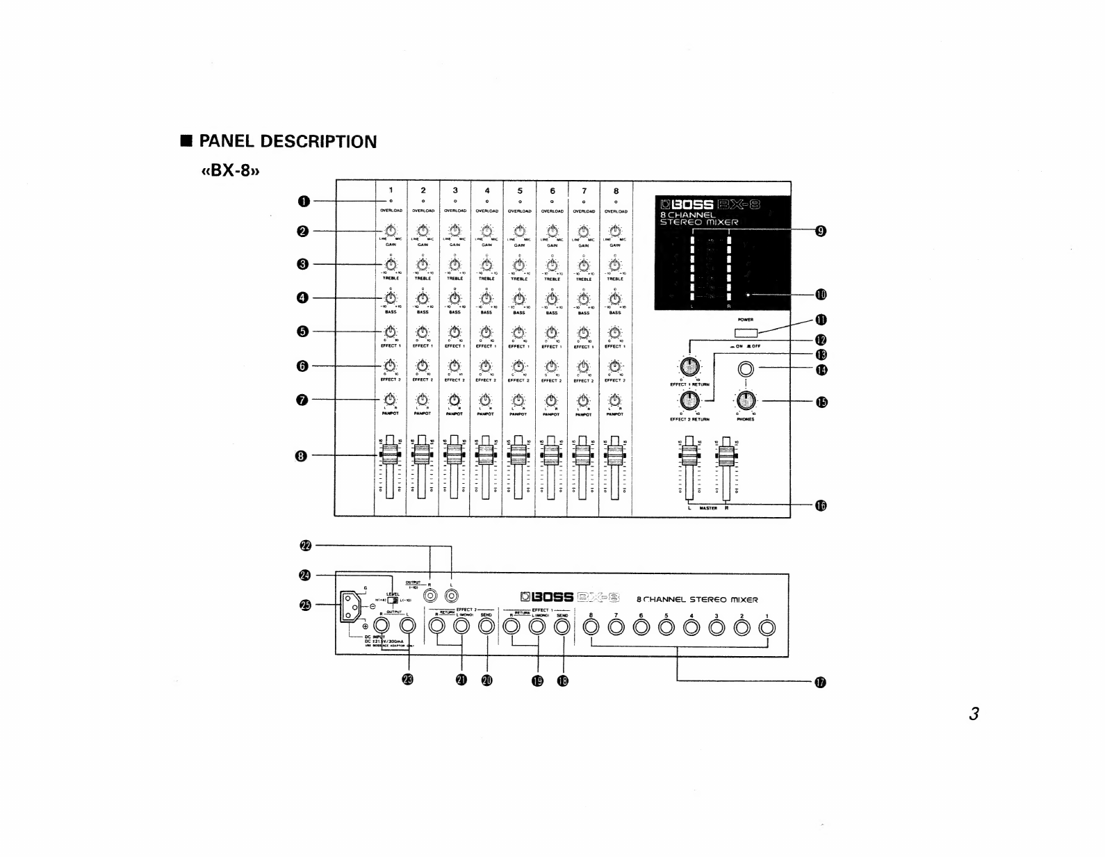
PANEL
DESCRIPTION
«BX-8»
1
7
DBOSS
|:
8
CHANNEL
STEREO
MIXER
OVERLOAD
-
2.
ae
a
ae
oe
o
3
‘+30
BASS
Pia
Sd
cd
oe
=
=
bad
=
i
EFFECT
1
€FFECT
1
T
=
ON
OFF
bo
6
"we
Fb
8
EFFECT
2
EFFECT
2
eo
89
6
6
8
8
6
EFFECT
2
RETURN
8 é
foo
titre’
OVprriretl
Muse
ee
Pd
orrirnty
se
rs
o
orrrreee
t
oo
ot
-o)
aR
t
© ©
OIBOSS
=".=S
a
cHaANNeL
STEREO
mixER
j
66606660066
mn
EFFECT
9
€FFECT
1
|p
RETURN
Lomo:
SEND
RFETUPS
|
(ono
®
e868
6
@
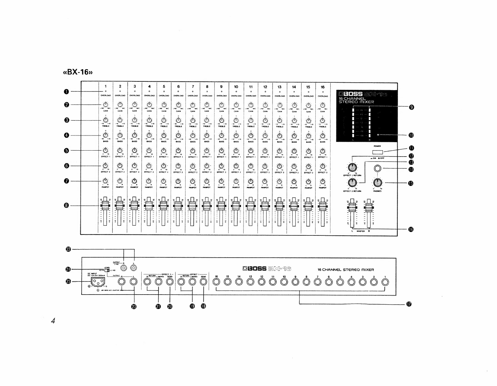
«BX-16»
5
6
°
3
12
13
14
15
16
o
os
2
oe
iJ
OVERLOAD
OVERLOAD
OVERLOAD
|
OVERLOAD
OVERLOAD
OVERLOAD
OVERLOAD
OVERLOAD
OVERLOAD
OVERLOAD
OVERLOAD
OVERLOAD
OVERLOAD
OVERLOAD
OVERLOAD
16
CHANNEL
STEREO
MIXER
ao
“
€FFECT
¢
€FFECT
1
EFFECT
t
EFFECT
1
EFFECT
1
EFFECT
1
EFFECT
t
EFFECT
1
SFFECT
EFFECT
t
EFFECT
1
€FFECT
1
EFFECT
1
EFFECT
Tt
€FFECT
ow”
oe
a
~
o
o
~M
EFFECT
2
EFFECT
2
EFFECT
2
|
EFFECT
2
«ON
BROFF
si
ow
oe
ow
a0
ow ow
oo
«M
o
om
aw
EFFECT
2
EFFECT
2
EFFECT
2
EFFECT
2
EFFECT
2
EFFECT
2
EFFECT
2
EFFECT
2
i
EFFECT
2
EFFECT
2
g
a
ee
6¢
©
6
8
8
8
Bcd
c7 wo
0
6
i
bcd
a]
wo
Ad
w
cd
hd
w
=
=
=f
al
2;
aa)
B<
ns
oy
2
10
i)
2
%
.
;
Fe
(ce
Ps
ee
OR
an
gl
-
-E
8]
. "
a
|
os a)
as
|
ke
.|
is
—._
a
s
eS
is
-
|
=.
-
|
-Bessl-
|
eS
|
= |
-B-
=)
|
-eS-
4
=
=
-
-
=
-
-
-
- -
- —
-
_
-
-
-
-
=
-'
-
a
-———
38
i
.
rg
ee
I
oe
ee
el
Seen
el
Soe
Shs
pees
Iie
Gast
arate
ce
-pd-
=tye
=
=
Ee
eee
a
feedlot
Gr
ee
me
ad
ee
Pee
ae
Fo
i
ag
eran
i
ee
=-}f-
=i
fe
i
S
Oo
o
s a
°o
3
o
cy
a
e
a
o
°
o
e
a
a
a
3
7
3
3
°
a
16
CHANNEL
STEREO
MIXER
EFFECT
2
|
EFFECT
1
OUTPUT
L
a
RETURN
wont
|
a
RETURN
60|66616656/6666666660666060
©}
use
s0ss
ace
soseton
0
j
®
@®
®@
® ®
®
@eee@e
@
@
Overload
Indicators
This
lights
up
when
the
input
signal
level
of
each
channel
is
too
high.
If
this
lights,
rotate
the
relevant
Gain
Knob
counterclockwise
to
decrease
the
input
sensitivity.
.
*
The
Overload
Indicators
light
up
when
the
level
of
the
signal
is
6dB
lower
than
the
clipping
level
(=the
level
where
the
sound
starts
being
distorted).
@
Gain
Knobs
The
Gain
Knobs
of
each
channel
adjusts
the
input
gain
for
mixing
the
signal
with
the
lowest
possible
noise
and
distortion.
Clockwise
rotation
raises
the
gain
(=increasing
the
volume).
©
Treble
Knobs
This
controls
treble
sounds.
Rotating
this
clockwise
will
boost
higher
frequencies
and
counterclockwise
cut
them.
@
Bass
Knob
This
knob
controls
bass
sounds.
Rotating
this
clockwise
will
boost
lower
frequencies
and
counterclockwise
cut
them.
@
Effect
|
Send
Knobs
These
knobs
control
the
level
of
the
signals
to
be
sent
to
the
Effect
1
Send
Jack.
Clockwise
rotation
increases
the
level.
For
instance,
when
a
reverb
unit
is
connected
to
the
Effect
1
Send/Return
Jacks,
rotating
this
knob
clockwise
will
deepen
the
reverb
effect.
*
The
output
from
the
Effect
1
Send
is
post
fader,
and
therefore
changes
depending
on
the
positions
of
the
Gain,
Treble,
Bass
and
Channel
Fader
Knobs.
@
Effect
2
Send
Knobs
These
knobs
control
the
level
of
the
signals
to
be
sent
to
the
Effect
2
Send
Jack.
Clockwise
rotation
increases
the
level.
For
instance,
when
a
reverb
unit
is
connected
to
the
Effect
2
Send/Return
Jacks,
rotating
this
knob
clockwise
will
deepen
the
reverb
effect.
*
The
output
from
the
Effect
2
Send
is
post
fader,
and
therefore
changes
depending
on
the
positions
of
the
Gain,
Treble,
Bass
and
Channel
Fader
Knobs.
@
Panpot
Knobs
Each
Panpot
Knob
routes
the
input
signal
from
an
input
Channel
to
the
left
and/or
right
mixing
busses.
By
means
of
the
Panpot
Knobs,
input
signals
can
be
sent
exclusively
to
one
mixing
bus,
or
the
other,
to
both
mixing
busses
equally
or
since
the
Panpot
Knob
is
Continuously
variable
to
both
mixing
busses
in
any
relative
proportion
desired.
©
Channel
Faders
This
adjusts
the
level
of
the
signal
sent
from
each
channel.
Raising
the
slider
will
increase
the
level,
and
lowering
it
will
decrease.
7
to
8
position
may
be
ideal
for
the
lowest
noise
and
distortion.
©
Level
Meters
These
indicate
the
level
of
the
output
signals.
When
“O”
of
the
Level
Meter
is
lit,
the
output
level
is
—10dBm
from
the
pin
jack,
and
from
the
standard
phone
jack
is
+4dBm
with
the
Output
Level
Selector
set
to
“+4",
and
—10dBm
when
it
is
set
to
“—10".
@
Pilot
Lamp
When
the
mixer
is
turned
on,
this
lamp
lights
up.
@
Power
Switch
This
turns
on
or
off
the
mixer.
When
it
is
turned
on,
the
Pilot
Lamp
lights
up.
*
Turn
on
or
off
the
mixer
with
the
Master
Faders
set
to
zero
@
Effect
1
Return
Knob
This
knob
controls
the
mixing
level
of
the
signal
returned
to
the
Effect
1
Return
Jacks
(L,R)
form
the
external
effect
(delay,
reverb,
etc).
Clockwise
rotation
increases
the
level.
Effect
1
Send/Return
Jacks,
this
knob
controls
the
overall
volume
of
the
reverb
sounds
while
the
Effect
1
Send
Knob
controls
the
reverb
level
of
each
channel.
®
Effect
2
Return
Knob
This
knob
controls
the
mixing
level
of
the
signal
returned
to
the
Effect
2
Return
Jacks
(L,R)
from
the
external
effect
(delay,
reverb,
etc).
Clockwise
rotation
increases
the
level.
@
Headphone
Jack
Connect
stereo
headphone
to
this
jack.
@
Headphone
Level
Knob
This
knob
controls
the
volume
of
the
headphone
sounds.
Rotating
this
clockwise
increases
the
volume.
*
The
Headphone
Level
circuits
are
completely
in-
dependent
from
the
Master
Fader,
therefore
you
can
monitor
sounds
through
headphones
even
the
Master
Fader
is
set
to
zero.
@
Master
Faders
(L,
R)
These
sliders
control
the
overall
volume
of
the
mixed
signals
separately
for
left
and
right.
Raising
the
slider
will
increase
the
volume
and
lowering
it
decrease.
The
optimum
level
with
the
lowest
noise
and
distortion
is
where
the
red
indicators
of
the
Level
Meters
light
occasionally.
@
Input
Jacks
These
are
input
jacks
for
connecting
to
a
mixing
device
such
as
microphone,
electronic
musical
instrument,
tape
deck
or
CD.
@
Effect
1
Send
Jack
This
is
an
output
jack
for
connecting
the
input
jack
of
an
external
effect
unit
(delay,
reverb,
etc).
Through
this
jack,
the
signal
which
has
been
level-adjusted
at
the
Effect
1
Send
Knob
of
each
channel
is
sent
out.

©
Effect
1
Return
Jack
(L,
R)
These
are
input
jacks
for
connecting
to
the
output
jacks
of
an
external
effect
(delay,
reverb,
etc).
Signal
fed
into
each
of
L
and
R
jacks
is
seaparately
level-adjusted
with
the
Effect
1
Return
Knob,
then
mixed
with
the
output
signal
in
stereo.
*
When
the
external
effect
unit
has
only
a
monaural
output,
connect
it
to
the
L
jack
on
the
mixer.
@
Effect
2
Send
Jack
This
is
an
output
jack
for
connecting
the
input
jack
of
an
external
effect
unit
(delay,
reverb,
etc).
Through
this
Jack,
the
signal
which
has
been
level-adjusted
at
the
Effect
2
Send
Knob
of
each
channel
is
sent
out.
@
Effect
2
Return
Jack
(L,
R)
These
are
input
jacks
for
connecting
to
the
ouput
jacks
of
an
external
effect
(reverb
or
delay
etc).
Signal
fed
into
each
of
L
and
R
jacks
is
separately
level-adjusted
with
the
Effect
2
Return
Knob,
then
mixed
with
the
output
signal
in
stereo.
*
When
the
external
effect
unit
has
only
a
monaural
output,
conect
it
to
the
L
jack
on
the
mixer.
@
Output
Pin
Jacks
(L,
R)
Through
these
pin
jacks,
mixed
signal
is
sent
out.
Con-
nect
these
to
a
tape
deck,
etc.
@®
Output
Jacks
(L,
R)
Through
these
jacks,
mixed
signal
is
sent
out.
Connect
these
to
a
power
amplifier,
etc.
@
Output
Level
Selector
Switch
This
switch
selects
output
level
of
the
signal
sent
from
the
Output
Jacks.
At
the
“+4”
position,
the
rated
output
level
(the
output
level
when
the
Level
Meter
0
is
lit)
is
+4dBm,
and
at
“—10",
itis
—10dBm.
@
AC
Adaptor
Connector
Connect
the
supplied
AC
adaptor
to
this
connector.

m@
CONNECTION
AC
Adaptor
(ACE
Series)
Tape
Deck
Tape
Deck
a
nod
Grrr
titi
Cri
a
CD
Player
(oxo)
OG
Speaker
Speaker
(Delay)

m
OPERATION
@
Make
all
the
necessary
connections,
then
set
each
(4)
Turn
the
mixer
on
and
make
sure
that
the
Pilot
Gain
Knob
to
“LINE”
position,
and
set
each
Chan-
Lamp
lights
up.
|
Fader
ce
r,
Eff
1
Return
Knob
an
wes
nel
Fader,
Master
Fader,
E
ee
7
.
S
ange
*
For
about
a
few
seconds
after
the
units
is
turned
Effect
2
Return
Knob
to
the
“0”
position.
;
.
on,
it
does
not
function
because
of
the
muting
2
circuit.
10
10
10
10
10
10
“
ly,
2
Situs
|
eis
-@-
:
:
a|
fio
si is
alle
a
LINE
“MIC
a
|
es
Sikes.
eee
GAIN
—=-
eS
-—--
POWER
=mON
BOFF
(2)
Set the
Output
Level
Selector
Switch
to
the
“+4”
:
or
“—10"
position
depending
on
the
type
of
the
@
Turn
on
the
units
connected
to
the
Output
Jacks
device
connected
to
the
Output
Jacks.
and
the
Output
Pin
Jacks,
such
as
a
power
amplifier,
tape,
deck,
etc.
le.g.]
+4dBm
:
PA
Equipment
©
Set
the
Channel
Fader
and
Master
Faders
to
“7”
—10dBm
:
Audio
Equipment
positions.
LEVEL
H(+4)
L(-10)
cae
—
so
wots
@)
Make
sure
that
the
mixer
is
turned
off,
and
con-
=
S-
=.
nect
the
supplied
AC
adaptor
to
the
AC
Adaptor
Ss
ie
oe
Ses.
“Say
(22
Connector,
then
the
power
plug
to
the
socket.
aie
a
eee
es
Be
221.5¥/300mA
L
MASTER
R
oJ
i
1S)
G
10
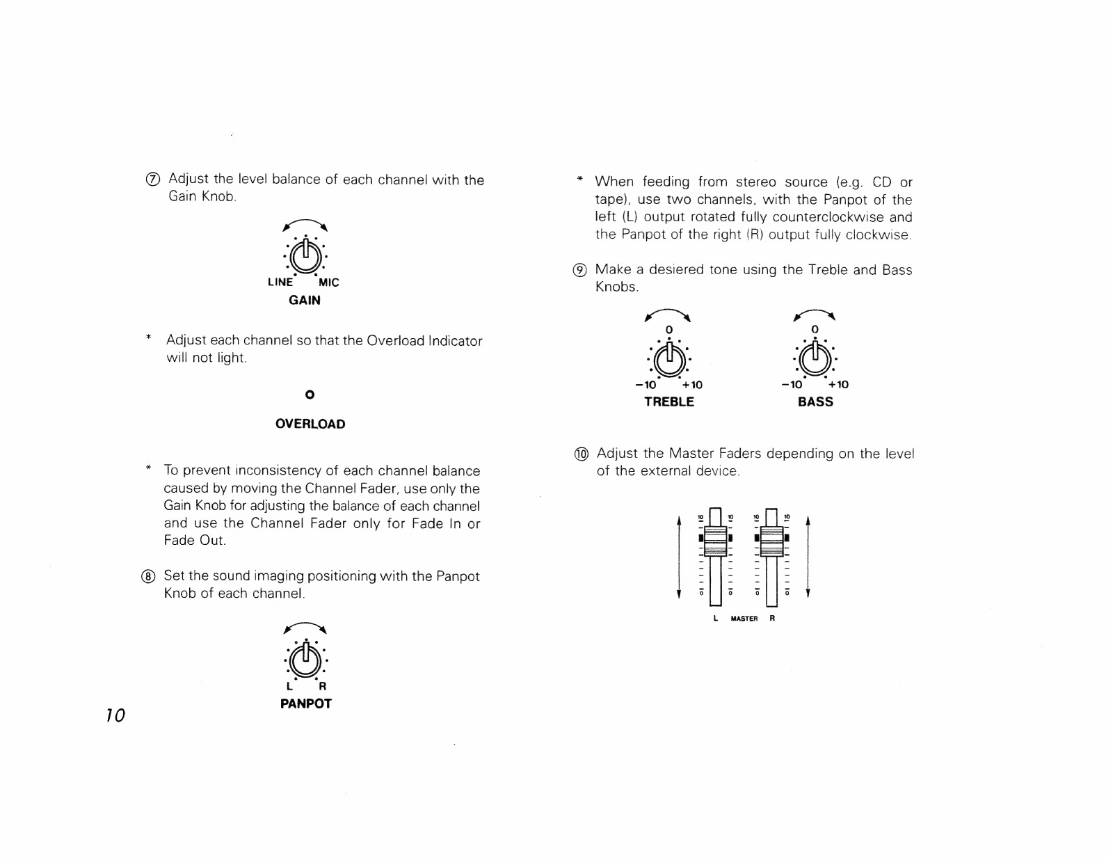
@
Adjust
the
level
balance
of
each
channel
with
the
Gain
Knob.
xO
LINE
‘MIC
GAIN
Adjust
each
channel
so that
the
Overload
Indicator
will
not
light.
O°
OVERLOAD
To
prevent
inconsistency
of
each
channel
balance
caused
by
moving
the
Channel
Fader,
use
only
the
Gain
Knob
for
adjusting
the
balance
of
each
channel
and
use
the
Channel
Fader
only
for
Fade
In
or
Fade
Out.
Set
the
sound
imaging
positioning
with
the
Panpot
Knob
of
each
channel.
When
feeding
from
stereo
source
(e.g.
CD
or
tape),
use
two
channels,
with
the
Panpot
of
the
left
(L)
output
rotated
fully
counterclockwise
and
the
Panpot
of
the
right
(R)
output
fully
clockwise.
(9)
Make
a
desiered
tone
using
the
Treble
and
Bass
Knobs.
xo™
x“rté<s.
)
9)
-10
+10
~10
“+10
TREBLE
BASS
(0)
Adjust
the
Master
Faders
depending
on
the
level
of
the
external
device.
15
opi
tt
itt
mrad
orlitrt
Cm
ita
of;
ri
itt
moet
orb
rt
id
t
Metts
L
MASTER
R

[Effect
Settings]
@
Set
the
external
effect
units
to
your
taste.
@
Set the
mixing
level
of
the
effect
sound
using
the
Effect
Return
Knob.
*
Usually,
set
this
to
the
“5”
position.
(To
increase
the
level
of
the
effect
sound,
set
to
a
higher
number
position.)
oO
0
om
‘0
EFFECT
1
RETURN
EFFECT
2
RETURN
(3)
Adjust
the
balance
of
effect
sound
using
the
Effect
Send
Knob
of
each
channel.
—"
mo
0
"10
o
#11
EFFECT
1
EFFECT
2
[Headphone
Level
Settings]
@)
Adjust
the
volume
of
the
headphones
using
the
Headphone
Level
Knob.
om
0
PHONES
*
Changing
the
Headphone
Level
Knob
does
not
affect
the
output
level.
1]
12
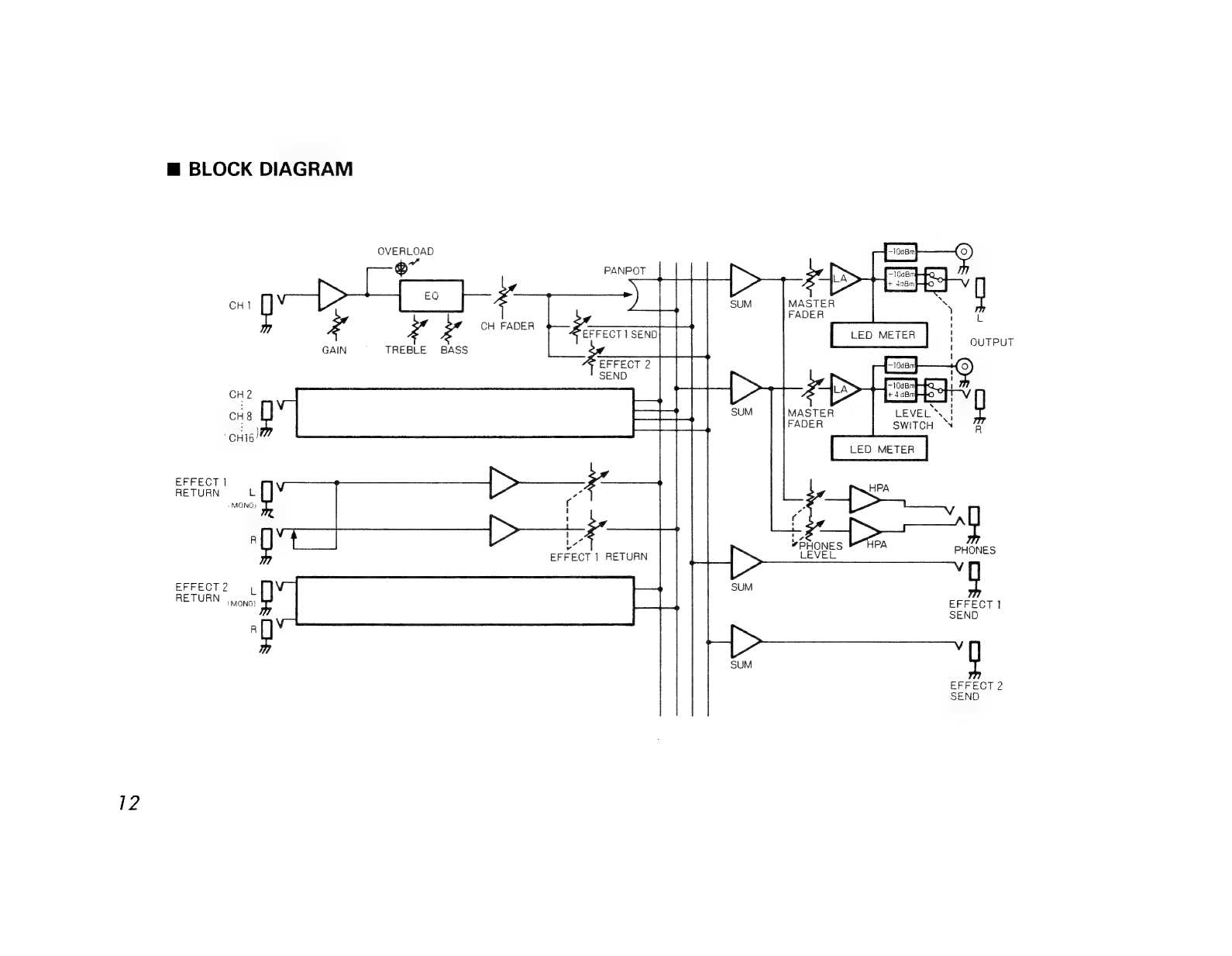
m@
BLOCK
DIAGRAM
OVERLOAD
a
®
PANPOT
>
:
me
y
CH]
a
CH
FADER
é
|
EFFECT
1
SEND
ae
GAIN
TREBLE
BASS
EFFECT
2
SEND
CH2
>
CHE
ae
ae
SUM
MASTER
;
pe
FADER
EFFECT
}
RETURN
L
(MONO)
>
q
a
»Etones
bTira
EFFECT
1
RETURN
Le
bEVEL
PHONES
EFFECT
2
ae
RETURN.
ai:
ma
_P.
SEND
;
iB
SUM
EFFECT
2
SEND
@
IMPORTANT
NOTES
Use
the
supplied
AC
Adaptor;
ACE-120,
220
or
240.
Using
any
other
adaptor
will
cause
trouble.
When
the
unit
is
not
to
be
used
for
a
long
period
of
time,
disconnect
the
AC
adaptor
from
the
socket.
Avoid
using
this
device
in
extreme
heat,
humidity
or
where
it
may
be
affected
by
dust
or
vibration.
Use
a
mild
detergent
and
soft
cloth
for
cleaning.
Do
not
use
solvents
such
as
thinner.
lf
this
unit
does
not
operate
properly,
unplug
the
power
cable
immediately
and
contact
your
local
Roland
service
center.
Switch
on
to
mixer
first,
then
the
power
amplifier.
Switch
off
the
power
amplifier
first,
then
the
mixer.
In
both
cases,
set
all
the
Faders
to
zero.
For
about
a
few
seconds
after
the
units
is
turned
on,
it
does
not
function
because
of
the
muting
circuit.
13
@
SPECIFICATIONS
«Common
for
the
BX-8
and
BX-16
Input
Level
Rated:
—50dBm
to
—10dBm
Input
Impedance
1.8kQ
to
100kQ
Output
Level
(Standard
Phone
Jack)
Rated:
+4dBm/—10dBm
Maximum:
+21dBm
Output
Level
(Pin
Jack)
Rated:
—10dBm
Maximum:
+7dBm
Output
Load
Impedance
More
than
10kQ
Effect
Send
Output
Level
(Rated):
—20dBm
Output
Load
Impedance:
more
than
10kO
Effect
Return
Input
Level
(Rated):
—20dBm
Input
Impedance:
47kO
14
Equalizer
Treble:
£10dBm/10kHz
Bass:
+10dBm/100Hz
Headphones
50mW/300
Equivalent
Input
Noise
—115
dBm
(|HF-A)
Frequency
Response
(at
the
minimum
gain)
20Hz
to
40kHz(*5dB)
@OdBm=0.775V
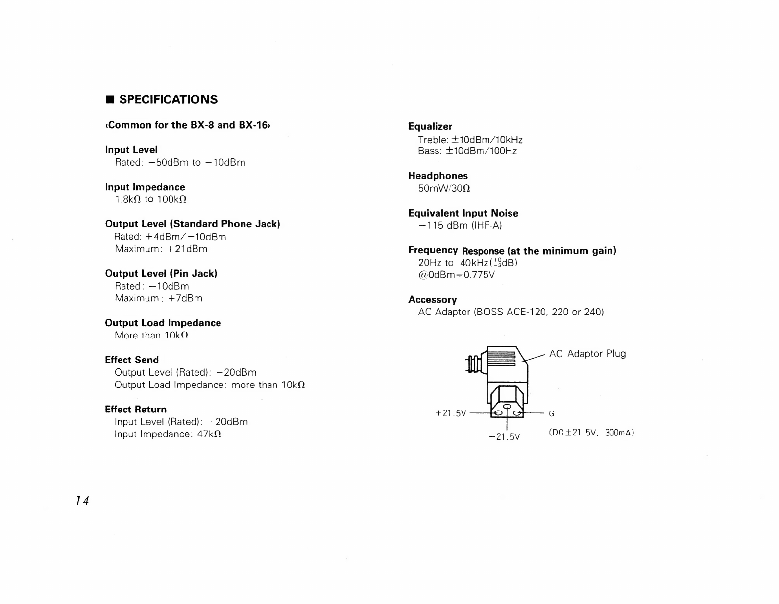
Accessory
AC
Adaptor
(BOSS
ACE-120,
220
or
240)
AC
Adaptor
Plug
#215
G
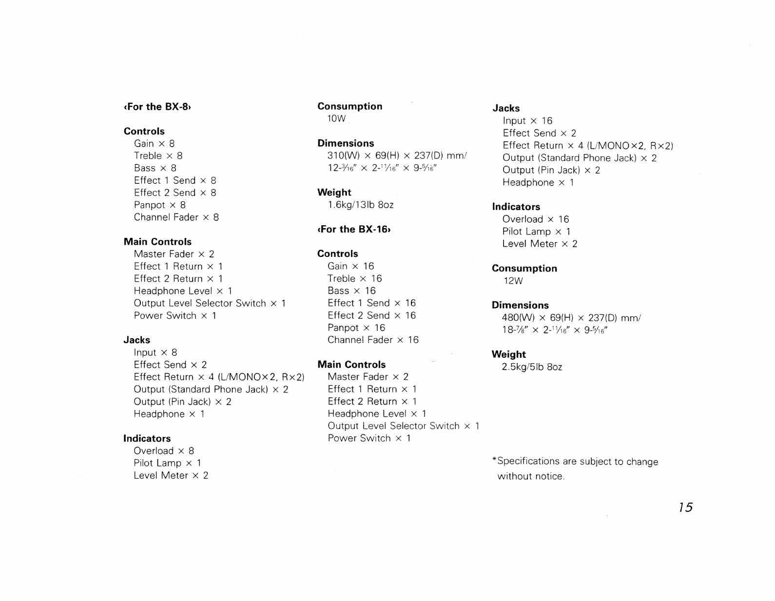
«For
the
BX-8
Controls
Gain
x
8
Treble
x
8
Bass
xX
8
Effect
1
Send
x
8
Effect
2
Send
x
8
Panpot
x
8
Channel
Fader
x
8
Main
Controls
Master
Fader
x
2
Effect
1
Return
x
1
Effect
2
Return
x
1
Headphone
Level
x
1
Output
Level
Selector
Switch
x
1
Power
Switch
x
1
Jacks
Input
x
8
Effect
Send
x
2
Effect
Return
x
4
(L/MONOX2,
Rx2)
Output
(Standard
Phone
Jack)
x
2
Output
(Pin
Jack)
x
2
Headphone
xX
1
Indicators
Overload
x
8
Pilot
Lamp
x
1
Level
Meter
x
2
Consumption
1OW.
Dimensions
310(W)
x
69(H)
x
237(D)
mm/
12-He"
«x
2-'V%e"”
xk
9-ea”
Weight
1.6kg/13lb
80z
«For
the
BX-16>
Controls
Gain
x
16
Treble
x
16
Bass
X
16
Effect
1
Send
x
16
Effect
2
Send
x
16
Panpot
x
16
Channel
Fader
x
16
Main
Controls
Master
Fader
x
2
Effect
1
Return
x
1
Effect
2
Return
x
1
Headphone
Level
x
1
Output
Level
Selector
Switch
x
1
Power
Switch
x
1
Jacks
Input
x
16
Effect
Send
x
2
Effect
Return
x
4
(L/MONO
x2,
Rx2)
Output
(Standard
Phone
Jack)
x
2
Output
(Pin
Jack)
x
2
Headphone
x
1
Indicators
Overload
x
16
Pilot
Lamp
x
1
Level
Meter
x
2
Consumption
12W
Dimensions
480(W)
x
69(H)
x
237(D)
mm/
18-74"
K
2-"Ve"
K
9-6”
Weight
2.5kg/5Ib
80z
*Specifications
are
subject
to
change
without
notice.
15
Information
@
Please
use
this
AC
adaptor
only
with
the
specified
device.
@
Please
use
the
AC
Adaptor
of
an
appropriate
voltage
(120,
220
or
240)
depending
on
the
voltage
system
in
your
country,
@
When
the
device
is
not
to
be
used
for
a
long
period,
be
sure
to
disconnect
the
AC
adaptor
(Power
Supply
Unit)
from
the
wall
outlet,
@When
you
need
repair
service,
call
your
local
Roland
Service
Station
as
shown
below
or
the
authorized
Roland
distributer
in
your
country.
U.S.A.
Roland
Corp
US
7200
Dominion
Circle
Los
Angeles,
CA.90040—-3647
ULS.A,
@B
(213)
685-5141
CANADA
Roland
Canada
Music
Ltd,
(Head
Office)
13880
Mayfield
Place,
Richmond
British
Columbia
Canada
V6V
2E4
@
(604)
270-6626
Roland
Canada
Music
Ltd.
3469--rue
Ashby
St-Laurent,
Quebec
H4R
2Cl1
®
(514)
335-2009
Roland
Canada
Music
Ltd.
Unit
B12—1515
Matheson
Blvd
Mississauga,
Ontario
L4W
2P5
@
(416)
625—4880
AUSTRALIA
Roland
Corporation
(Australia)
Pty.
Ltd.
(Head
Office)
38
Campbell
Avenue
Dee
Why
West,
NSW
2099
Australia
@
(02)
982-8286
Roland
Corporation
(Australia)
Pty.
Ltd.
(Melbourne
Office)
50
Garden
Street
South
Yarra,
Victoria
3141
Australia
@
(03)
241-1254
NEW
ZEALAND
Roland
Corporation
(NZ)
Ltd.
9
Nugent
Street,
Grafton
Auckland
3
New
Zealand
@
(09)
398-715
UNITED
KINGDOM
Roland
(UK)
Ltd.
Great
West
Trading
Estate
©
983
Great
West
Road
Brentford,
TW8
SDN,
Middlesex,
England
@
(Ol)
568
4578
WEST
GERMANY
Roland
Elektronische
Musikinstrumente
Handelsgesellschaft
mbH.
Oststrasse
96,
2000
Norderstedt
West
Gernfany
040,526
0090
BELUGIUM,HOLLAND
LUXEMBOURG
Roland
Benelux
N.V.
Houtstraat
1
B-2431
Oevel—Westerlo
Belgium
@BO0l4—58
45
35
DENMARK
Roland
Scandinavia
AS
Norre
Sogade
49,
1370
Copenhagen
K.
Denmark
@
(01)
11
31
11
SWEDEN
Roland
Scandinavia
A.’S
Storskarsgatan
4
115
29
Stockholm
Sweden
B08-65
32
40.65
32
50
NORWAY
Benum
Music
A.“S
Haakon
den
godes
Vei
14
N-0319
Oslo
3,
Norway
(Box
145
Vinderen,
N—0319
Oslo
3
Norway)
:
B02
141266
FINLAND
OY
Musiikki
Fazer
Musik
AB
Takomaotie
3
00380
Helsinki
38,
Finland
B05
56551
ITALY
Roland
Italy
S.p.A.
Via
Gallarate
58
20151
Milano
ltaly
@&02—3086849
SWITZERLAND
Musitronic
AG
Gerberstrasse
5,
CH—4410
Liestal
Switzerland
@B061/91
16
15
OL
FRANCE
Musikengro
102,
Avenue
Jean—Jaures
69007
Lyon
Cedex
07
@
(7)
858-54
60
Musikengro
(Paris
Office)
Centre
Region
Parisienne
41
rue
Charles—Fourier,
94400
Vitry
s.Seine
&G
(1)
680
86
62
SPAIN
Vietronic
S.A.
Bolivia
239
08020
Barcelona
@93-—307
47
12
AUSTRIA
E.
Dematte
&
Co.
Nue—Rum
Siemens—Strasse
4
A-—6021
Innsbruck
box
591
®
(05222)
63
451
GREECE
A.
ANDREADES
&
Co.
L.T.D.
2
Phidiou
street,
GR
10026B
Athens
&
3620130
Products
of
Roland
Printed
in
Japan
Jun.
‘88
E-3
SIL/B=2K
ts]
~
IMT
odn
o0£
L90E092
00Z1L90E092
pugoy=!
Other manuals for BX-8
1
This manual suits for next models
1
Other BOSSCO Music Mixer manuals

BOSSCO
BOSSCO BX-800 User manual

BOSSCO
BOSSCO BX-800 User manual

BOSSCO
BOSSCO KM-60 Operating and maintenance manual

BOSSCO
BOSSCO Gigcaster 5 User manual

BOSSCO
BOSSCO BX-8 User manual

BOSSCO
BOSSCO MX-10 User manual

BOSSCO
BOSSCO KM-600 keyboard mixer User manual

BOSSCO
BOSSCO Gigcaster 5 User manual

BOSSCO
BOSSCO Gigcaster 8 User guide

BOSSCO
BOSSCO BX-4 User manual


