Botanicare SLIDE BENCH User manual

SLIDE BENCH ASSEMBLY
INSTRUCTIONS
Revision 5.7
PN: 50519

Page | 2 Technical Support 1-888-808-4826
Important Safety Precautions
Read and follow all warnings and instructions before using the Botanicare® Slide Bench. Failure
to heed direction could lead to serious personal injury, damage to the Slide Bench, or property
damage.
•The Slide Bench must always be placed on and anchored to a concrete surface that is
level and void of any large cracks. Failure to do so could result in the bench tipping
over unexpectedly.
•Use approved anchors as defined on the next page.
•Do not load the Slide Bench with more than 25 pounds per square foot.
•Do not climb on or in the Slide Bench or Trays.
•All steps in this assembly procedure must be completed prior to using the bench.
•Keep fingers and hands away from the rollers. The table rollers can cause injury.
•Keep fingers and hands away from the anti-tip brackets. Do not use the brackets to
move the bench. Fingers or hands can be caught between the bracket and the frame
causing injury.
•Do not extend threaded shafts more than the maximum spacing defined.
•Do not drill anchors into post tension slabs.
•Never move the bench with People or Equipment in between the benches as this could
cause injury to personnel or damage to Equipment.
Before using BOND THREE Lap Tray Sealant Adhesive, carefully read and follow all warnings
and directions for use, on package and in instructions.
Before You Get Started
Please take the time to read all the assembly instructions before attempting to assemble your
Botanicare® Slide Bench.
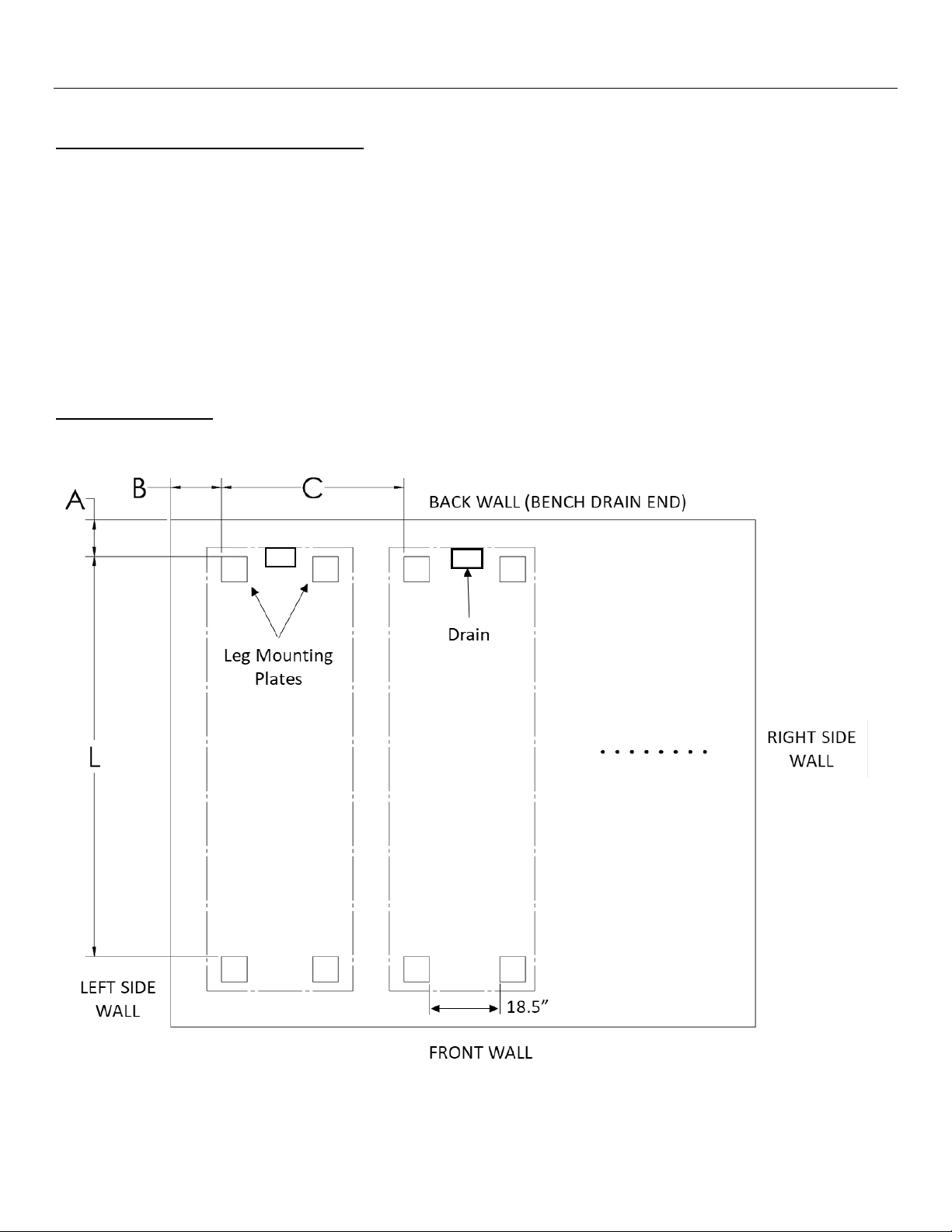
These instructions show assembly of a 20’ bench as an example. All steps apply for benches of
different lengths.

Page | 3 Technical Support 1-888-808-4826
Tools Needed
The following tools & supplies are required to complete this assembly of the slide bench.
•Cordless Drill with clutch
•Hammer Drill
•Tape Measure
•String Line or Layout Laser
•Chalk Line
•Level
•Hammer or Mallet
•Combination Wrench or 15/16” Box
Wrench
•3/8” Magnetic Nut Driver Drill Bit
•5/16” Magnetic Nut Driver Drill Bit
•¼” Masonry Drill Bit
•Rubbing Alcohol
•Clean Cloth Rags
•Caulk Gun
•1 3/8” Step Drill Bit
Anchors Not Included
Installation of the bench systems will require ¼” x 2¼” wedge style concrete anchors.
Installation of the anchors should follow the anchor manufacturer’s recommendations.
Acceptable wedge style anchor
Setting the Drill Clutch
CAUTION: Overtightening screws using a drill can result in stripping the threads in aluminum
parts.
•Every drill is different, use caution until familiarity with the drills capabilities.
•Use the lowest setting on the drill clutch that will install the screws.
•A higher torque may be required to initially cut the threads, reduce torque for final
tightening.
•After installing, hand tightening will help prevent stripping threads.
NOTE: There is a repair kit available should a screw strip out a hole.

Page | 4 Technical Support 1-888-808-4826
(MS3292)
12” (MS3282)
20”,30” (MS3284)
4’ (MS3296)
5’ (MS3431)
Hardware
(A)Frame Tube
Long
(B)Frame Tube
Short
(C) - Table Tube
Long
(D) - Table Tube
Short
(E) - Arch Tube
(F) Roller Tube
Long
(G) Roller Tube
Short
(H) Anti-Tip
Frame
(I) Guide Bracket
(J) Table
Extrusion
(K)Frame Leg
(L) Threaded Rod
(M) Frame
Connector
(N)Corner
Bracket
(O) Trellis Bracket
(MS3295)
(MS3286)
(MS3290)
(MS3257)
(MS3294)
(MS3288)
(MS3300)
(MS3301)
12” (MS3258)
20” (MS3283)
30” (MS3285)
(MS3281)
(MS3289)
(MS3297)

Page | 5 Technical Support 1-888-808-4826
(MC2081)
(MC2082)
(P) Roller Ends
(Q) Roller
Connector
(R) Drain Screen
(S) Handle
(T) Roller Spacer
(U) Drain Tray
(V) Middle Tray
(W) End Tray
¾” Bulkhead
Drain Fitting
1” Bulkhead
Drain Fitting
(X) Bump Stop
(Y) 1” Square
Tube Cap
(Z) 5/
8
” Hole
Plug
5/
8
”-11 Hex Nut
5/
8
” Flat Washer
¼”–20 x 3/
8
”
Flanged Hex
Head Screw
10-32 x 1” Thread
Cutting Hex Head
Screw
10-32 x ½”
Thread Cutting
Hex Head Screw
10-16 x ½” Self-
Drilling Screw
10-24 x ½”
Thumb Screw
BOND THREE (Adhesive) (50515)
(MS3287)
(MS3293)
(50001)
4’ (50520)
5’ (50029)
4’ (50521)
5’ (50042)
4’ (50522)
5’ (50043)
(50005)
(50003)
(MC2085)
(MC2083)
(MC2084)
(MS3255)
(MS3256)
(MS3271)
(MS3299)
(MS3291)
(MS3260)
(MS3298)

Page | 6 Technical Support 1-888-808-4826
Basic Bench Dimensions
As an example, a 20 foot bench is 48 inches wide by 246 inches long. The bench table top allows
for plus or minus 8.5 inches of travel (or movement) side to side, measured from the center
position, or 17 inches total travel from the left stop to the right stop.
Maximum Threaded Rod Extension
Warning: Do not extend the threaded rods too far from the legs. Doing so may result in the
failure of the bench resulting in equipment damage and injury.

Page | 7 Technical Support 1-888-808-4826
THIS PAGE IS LEFT INTENTIONALLY BLANK

Page | 8 Technical Support 1-888-808-4826
Bench Assembly and Installation
Step 1. Multi-Bench Room Layout
Use the room layout calculator tool to determine the quantity, position, spacing and desired
room aisle widths between and around the benches.
ALWAYS layout the entire room prior to assembly of hardware
NOTE: Precise layout of the room prior to the assembly of any benches will help in achieving
the desired spacing around and between the benches. Always verify layouts are square by
checking the diagonal distance. Do not rely on the walls being straight or square.
Room Orientation
For the purpose of these instructions the following room orientation will be used.

Page | 9 Technical Support 1-888-808-4826
Determine layout distances
A. Drain Tray to Wall Spacing
Distance A
Enter desired spacing here
+ 5 1/8” =
B. Left Side Tray to Wall Minimum Spacing
(When bench is slid towards the wall)
Distance B
Enter desired minimal spacing here
+ _______ =
4’ bench add 19 1/4"
5’ bench add 25 1/4"
C. Bench to Bench Spacing
(17” aisle minimum)
Distance C
Enter desired aisle width here
+ _______ =
4’ bench to 4’ bench spacing add 31”
4’ bench to 5’ bench spacing add 37”
5’ bench to 5’ bench spacing add 43”
D. Distance “L” from Arch 1 leg mounting plate to the last arch mounting plate. Select from
the table based on the nominal bench length.
Bench Length
Distance L
Bench Length
Distance L
Bench Length
Distance L
15’
174”
45’
534”
75’
894”
20’
234”
50’
594”
80’
954”
25’
294”
55’
654”
85’
1014”
30’
354”
60’
714”
90’
1074”
35’
414”
65’
774”
95’
1134”
40’
474”
70’
834”
100’
1194”
E. Distance A from the back wall, snap a chalk line along the back wall from left to right.
F. Distance B from the left wall, snap a chalk line along the left wall from back to front.
G. Distance C from the line created in step F, snap a parallel chalk line from back to front.
Repeat as necessary based on the number of benches to be installed in the room.
NOTE: Arches are nominally 60” from arch to arch. The last arch opposite the drain end, is a
short section and is only 54” apart.

Page | 10 Technical Support 1-888-808-4826
Step 2. Arch Assembly
NOTE: If the assembled bench is to include slope for faster
drainage use the table provided to assemble each arch with
appropriate height.
TIP: Label each arch with the arch number.
TIP: Snug threaded rod nuts to prevent movement of
hardware.

Page | 11 Technical Support 1-888-808-4826
10 15 20 25 30 35 40 45 50 55 60 65 70 75 80 85 90 95 100
1
(Drain) 0 0 0 0 0 0 0 0 0 0 0 0 0 0 0 0 0 0 0
25/8 5/8 5/8 5/8 5/8 5/8 5/8 9/16 1/2 7/16 7/16 3/8 3/8 5/16 5/16 5/16 1/4 1/4 1/4
31 1/4 1 1/4 1 1/4 1 1/4 1 1/4 1 1/4 1 1/4 1 1/8 115/16 13/16 3/4 3/4 11/16 5/8 9/16 9/16 1/2 1/2
41 7/8 1 7/8 1 7/8 1 7/8 1 7/8 1 7/8
1 11/16
1 1/2 1 3/8 1 1/8 1 1/8 1 1/16 115/16 7/8 13/16 13/16 3/4
52 1/2 2 1/2 2 1/2 2 1/2 2 1/2 2 1/4 21 13/16 1 11/16 1 9/16 1 7/16 1 5/16 1 1/4 1 3/16 1 1/8 1 1/16 1
63 1/8 3 1/8 3 1/8 3 1/8 2 3/4 2 1/2 2 1/4 2 1/16 1 15/16 1 13/16 1 11/16 1 5/8 1 1/2 1 3/8 1 5/16 1 1/4
73 3/4 3 3/4 3 3/4 3 5/16 32 3/4 2 1/2 2 5/16 2 1/8 21 7/8 1 3/4 1 11/16 1 9/16 1 1/2
84 3/8 4 3/8 3 7/8 3 1/2 3 3/16 2 15/16 2 11/16 2 1/2 2 5/16 2 3/16 2 1/16 1 15/16 1 13/16 1 3/4
954 7/16 43 5/8 3 5/16 3 1/16 2 7/8 2 11/16 2 1/2 2 3/8 2 1/4 2 1/8 2
10 54 1/2 4 1/8 3 3/4 3 7/16 3 3/16 32 13/16 2 5/8 2 1/2 2 3/8 2 1/4
11 54 9/16 4 3/16 3 7/8 3 9/16 3 5/16 3 1/8 2 15/16 2 3/4 2 5/8 2 1/2
12 54 9/16 4 1/4 3 15/16 3 11/16 3 7/16 3 1/4 3 1/16 2 7/8 2 3/4
13 54 5/8 4 5/16 43 3/4 3 1/2 3 5/16 3 3/16 3
14 54 5/8 4 5/16 4 1/16 3 13/16 3 5/8 3 7/16 3 1/4
15 54 11/16 4 3/8 4 1/8 3 7/8 3 11/16 3 1/2
16 54 11/16 4 7/16 4 3/16 3 15/16 3 3/4
17 54 11/16 4 7/16 4 3/16 4
18 54 3/4 4 1/2 4 1/4
19 54 3/4 4 1/2
20 54 3/4
21 5
20" & 30" Arch Height Adjustment Distance for Slope (Fractional Inches)
Arch
Number
Nominal Bench Length (ft)

Page | 12 Technical Support 1-888-808-4826
10 15 20 25 30 35 40 45 50 55 60 65 70 75 80 85 90 95 100
1
(Drain) 0 0 0 0 0 0 0 0 0 0 0 0 0 0 0 0 0 0 0
25/16 5/16 5/16 5/16 5/16 5/16 5/16 1/4 1/4 1/4 3/16 3/16 3/16 3/16 1/8 1/8 1/8 1/8 1/8
35/8 5/8 5/8 5/8 5/8 5/8 5/8 9/16 1/2 7/16 7/16 3/8 3/8 5/16 5/16 5/16 1/4 1/4 1/4
415/16 15/16 15/16 15/16 15/16 15/16 13/16 3/4 11/16 5/8 9/16 9/16 1/2 1/2 7/16 7/16 3/8 3/8
51 1/4 1 1/4 1 1/4 1 1/4 1 1/4 1 1/8 115/16 13/16 3/4 11/16 11/16 5/8 9/16 9/16 1/2 1/2
61 9/16 1 9/16 1 9/16 1 9/16 1 3/8 1 1/4 1 1/8 1 1/16 15/16 7/8 13/16 3/4 3/4 11/16 11/16 5/8
71 7/8 1 7/8 1 7/8
1 11/16
1 1/2 1 3/8 1 1/4 1 1/8 1 1/16 115/16 7/8 13/16 13/16 3/4
82 3/16 2 3/16
1 15/16
1 3/4 1 9/16 1 7/16 1 3/8 1 1/4 1 3/16 1 1/8 1 1 15/16 7/8
92 1/2 2 1/4 21 13/16 1 11/16 1 9/16 1 7/16 1 5/16 1 1/4 1 3/16 1 1/8 1 1/16 1
10 2 1/2 2 1/4 2 1/16 1 7/8 1 3/4 1 5/8 1 1/2 1 3/8 1 5/16 1 1/4 1 3/16 1 1/8
11 2 1/2 2 1/4 2 1/16 1 15/16 1 13/16 1 11/16 1 9/16 1 1/2 1 3/8 1 5/16 1 1/4
12 2 1/2 2 5/16 2 1/8 1 15/16 1 13/16 1 3/4 1 5/8 1 1/2 1 7/16 1 3/8
13 2 1/2 2 5/16 2 1/8 21 7/8 1 3/4 1 11/16 1 9/16 1 1/2
14 2 1/2 2 5/16 2 3/16 21 15/16 1 13/16 1 11/16 1 5/8
15 2 1/2 2 5/16 2 3/16 2 1/8 1 15/16 1 13/16 1 3/4
16 2 1/2 2 3/8 2 3/16 2 1/16 21 7/8
17 2 1/2 2 3/8 2 1/4 2 1/8 2
18 2 1/2 2 3/8 2 1/4 2 1/8
19 2 1/2 2 3/8 2 1/4
20 2 1/2 2 3/8
21 2 1/2
12" Arch Height Adjustment Distance for Slope (Fractional Inches)
Arch
Number
Nominal Bench Length (ft)

Page | 13 Technical Support 1-888-808-4826
Step 3. Frame Assembly
NOTE: Assemble the frame in roughly the final position that it will be installed in the room.
NOTE: Start with the end of the bench where the drain will be located. This will be Arch 1
from step 2.

Page | 14 Technical Support 1-888-808-4826
Step 4. Anchor Frame
NOTE: Follow anchor manufacturer’s instruction to properly drill and install anchors.
CAUTION: All leg mounting locations must have the anchors installed and properly tightened
to prevent damage to the bench or a failure of a component that could lead to injury to
personnel.
CAUTION: Do not drill into post tension slabs.
Align edge of foot plates to chalk lines from Step 1, drill and install anchors

Page | 15 Technical Support 1-888-808-4826
Step 5. Level Frame
Level each arch from side to side so the table doesn’t roll to the low side.
Tighten top and bottom Hex Nuts as each arch is leveled.

Page | 16 Technical Support 1-888-808-4826
Step 6. Roller Tube Assembly
NOTE: All short roller tubes get one (1) roller end, all long roller tubes get one (1) roller
connector on one end.
CAUTION: Do not overtighten screws as this will cause the threads to strip out of the rollers
Two roller assemblies per Bench.

Page | 17 Technical Support 1-888-808-4826
THIS PAGE IS LEFT INTENTIONALLY BLANK

Page | 18 Technical Support 1-888-808-4826
Step 7. Table Assembly (4’ Wide Bench
Assemble the table top in 5 foot sections as you continue to work down the length of the bench.
CAUTION: Roll each roller assembly to the appropriate outside stop to provide a stable
platform for assembly of the table.
NOTE: Only 2 of every 3 long and short table tubes get brackets attached.

Page | 19 Technical Support 1-888-808-4826
CAUTION: Do not overtighten screws as this will cause the threads to strip out.
NOTE: Install bottom screws last for a better fit between tubes and extrusion.
Install outer tubes first
Install Middle Tube after outer tubes

Page | 20 Technical Support 1-888-808-4826
Step 7. Table Assembly (5’ Wide Bench)
Assemble the table top in 5 foot sections as you continue to work down the length of the bench.
CAUTION: Roll each roller assembly to the appropriate outside stop to provide a stable
platform for assembly of the table.
NOTE: Only 4 of every 5 long and short table tubes get brackets attached.
Table of contents
Other Botanicare Lawn And Garden Equipment manuals