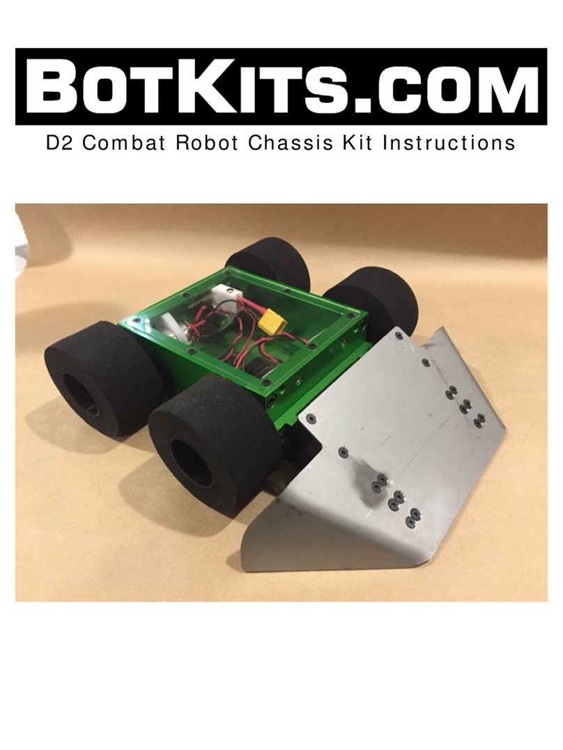
BotKits.com D2 COMBAT ROBOT KIT User manual

D2CombatRobotChassisKitInstructions
CAUTION:THISROBOTISPOWERFULANDFAST!MAKESUREYOUONLYOPERATE
THEROBOTINANAREAWHEREITCANNOTCAUSEDAMAGEORINJURY!

1|Page
1 ADDITIONALPARTSREQUIRED:
Speedcontroller(weusetheScorpionMiniElectronicSpeedControl[ESC])
Radio(weusetheSpektrumDX3CtransmitterandaSR301receiver)
Battery(weusetheTurnigyNano‐Tech850mAh4SLiPopack)
Batteryplugfortheprimaryleadsplugonyourselectedbattery(XT60forourbatteries)
Foamsheetorbubblewraptosecurebattery(weusebubblewrap)
LiPobatterycharger
2 TOOLSREQUIRED:
(TorxT10screwdriver–providedwithkit)
SAEAllenwrenchset
#2Philipsheadscrewdriver
Wirestripper
Solderingironandsolder
BlueLoctite
2.1 ATTENTION:
Pleasepaycloseattentiontowhichfastenersgowhere.Trytokeepthemintheirindividually
labeledpouchesuntiltheyarereadyforinstallation.Manyofthemlookthesame,butareslightly
differentinlength.Usequalitytools!IfanAllenwrenchorscrewdriverfitsalittleloose,fastener
damageandfrustrationwillresult.Takeyourtime,havefun!!

2|Page
3 A
SSEMBLY
:
3.1 S
TEP
1
–
T
EMPORARYASSEMBLY
:
Formthebasicchassisbyassemblingthe2sides,2ends,4motors,switch,andpowerLED:
Attachall4oftheplasticmotorbracestothealuminumendpiecesusingthesupplied#6x5/8”
flatheadsheetmetalscrewsanda#2Phillipsscrewdriver.
Slidethemotorsintothemotorbores,untiljusttheblackheadofthemotor(wheretheshaft
comesout)isextendingbeyondthesideoftherobot.
Looselyinstall4ofthe10‐24x3/4socketheadcapscrewsinthelowerholesoneachend(e.g.
floppily)toconnecttheendstothesides.Thereisnoup/down/left/right.Allofthesidesand
endscanbeusedinanyposition(thelargehollowedoutareasgotowardstheinsides).
Snug(e.g.,fingertight)the4screwssothemotorsaretemporarilyheldinplace.
Attachthealuminumbottomplatetothechassisusing4oftheM3x6mmmachinescrewsand
theincludedTorxscrewdriver.

3|Page
3.2 S
TEP
2
–
A
RRANGE
E
LECTRONICS
:
Arrangeyourbattery,receiver,andspeedcontrolleronthebottomplate,asyouexpecttoplacethemin
thefinishedrobot.
Thebatteryisintherejusttomakesuresufficientroomisbeing
leftforit.
Makesurethereissufficientclearancebetweeneverythingand
themotors,allowingforspacingupofthereceiverandspeed
controlwhentheyareattachedusingtheincludedVelcro.
Markthelocationofyourreceiverandspeedcontrolleronthe
bottomplate.
3.3 S
TEP
4
–
A
TTACH
E
LECTRONICS
:
AttachyourreceiverandspeedcontrollerusingtheVelcro.
MakegooduseoftheVelcrobymakingsurethatpartsaremountedfirmlyenough(as
shown).
3.4 S
TEP
5
–
W
IRING
P
REPARATION
:
Determinewirelengthsneededtoconnectyourmotorstoyourspeedcontrolandfromthebatteryto
theswitchandspeedcontrol:
Measurefromthemotorsolderlugstothespeedcontrollugs.
Placethebatteryinthechassis,anddeterminewirelengthsneededtoconnecttothepower
switch.Thenegativewillgofromthebatterytothenegativecontactontheboardandthe
positivewilldothesamebutwillbeinterruptedbytheswitch.
Trimthewirestosizeandstriptheendsallowinga5mmcontactoneachend.
Foreasierassembly,tinthewiresaftertheyhavebeencutandstripedtolength.
Atthesametime,trimthepowerLEDleadstoanappropriatelengthtoconnecttothepower
lugsonthespeedcontrol,andtinifdesired.

4|Page
3.5 S
TEP
6
‐
W
IRING
:
Youwillbesolderingthewirestothemotorsandbatteryplugandconnectingthemtothespeed
controller.
Removeoneofthesidesoftherobottoallowforeasyspeedcontrolleraccess.
Solderwirepairstothemotorlugs,beingcarefulnottooverheatthemotorlugs.IMPORTANT:
DoNOTusesilversolder.Thehighertemperatureoverheatsthemotorinternals,causing
prematuremotorfailure.Wefinditeasiesttotinthewireendsandmotorlugs,thenjointhem.
ConnecttheLEDtothemainpowerinputonthespeedcontrol,sothatitiseasytotellwhenthe
robotislive.
Soldermainpowerpositivewirestothepowerswitch.Attachtheotherendtothepositive
terminalofanappropriateplugforyourselectedbattery.
Soldermainpowernegativewiretothenegativeterminalofthebatteryplug.
Placetheswitchinthe3Dprintedmounttokeepitoutoftheway.
Slide2ofthemotorsintothechassis.IMPORTANT:Themotorsarewiredinparallel,soitis
importantthatplacethefirst2motorsonthesameside.Itdoesnothowevermatterwhich
portontheSpeedcontrollertheypluginto(shown).
FitthefourmotorwiresintomotoroutputC4,positiveintopositiveandnegativeintonegative.
Thentightentheterminals.

5|Page
SlotthenexttwomotorsintotheirmountsandplacethefourwiresinterminalC3tightening
theterminalswhenfinished.
ConnectTHRandSTRtoyourradiotransmitterofchoice,asshown.Note:Itwillnotdamage
theelectronicsifyouflipthembutitwillreversedrivingandturningcontrols.
3.6 S
TEP
7
‐
A
SSEMBLETHEROBOT
:
Carefullyattachalloftheplatesastheendofconstructiondrawsnear.
Slidetheothersideplatebackontothechassis.
Snugthebottomscrews
Addtheuppersetof10‐24machinescrews,thentightentheupperscrews.Thiswillresultinthe
lowerscrewsbecomingtight,asweachieveacompressionfitaroundthemotorgearbox.Hint:
Whileevenlytighteningthe10‐24x¾screws,lookcloselyattheairgapbetweenthesideplates
andendplates.Tightenthescrewsinsmallincrementstokeeptheairgapseven.Evenairgaps
equalasquarelyassembled,strongrobot.
Attachthelowerplate,using8ofthesuppliedM3machinescrews.UseblueLoctitetokeep
thesescrewsfromcominglooseduringcombat!
Lightlyplacetheclearupperplateonthechassisandgentlyattachitwiththe4M3screws.
Lightlyattachingitisimportantbecauseyouwillwanttoaccesstheelectronicsalittlelater.
Ifyouwillbefightinginanarenawithasteelfloor,weofferoptionalmagnetsthatcanbe
attachedtothebottomoftherobottoincreasetraction.
3.7 S
TEP
8
‐
A
TTACH
W
HEELS
:
Attachaxleadaptersontheaxlesandmountthewheels.
Looselyscrewthesupplied4‐40machinescrewsintotheblackaluminumaxleadapters.
Slideeachaxleadapterfullyontoamotorshaft,withtheclampportiontowardsthechassis,and
tightenthe4‐40machinescrewstosecuretheadapterstothemotorshafts.
Slideawheelontoeachoftheaxleadapters,andsecurewiththesupplied6‐32machinescrews.
Your4‐40sizedAllenwrenchcanbeusedtohelpaligntheholesinthewheelhubwiththe
tappedholesintheaxleadapters.

6|Page
3.8 S
TEP
9
‐
A
TTACH
B
LADE
A
SSEMBLY
:
Mountthetitaniumblade,completingthebuild.
Attachthebladetothebladebrackets,usingthesuppliedM3machinescrewsandtheTorx
screwdriversuppliedwithyourD2CombatRobotChassiskit.Thesmalltipsofthebracketsgo
towardstheloweredgeoftheblade.UseblueLoctitetokeepthesescrewsfromcomingloose
duringcombat!
Attachthebladebracketstotheblademount,usingthesupplied¼‐20x0.875”socketheadcap
screws.Leavethescrewslooseenoughthatthebracketsrotatefreelyonthemount.Secure
the¼‐20machinescrewsbyusingthesupplied¼‐20nuts,sothemachinescrewscan’tunscrew
duetovibration,etc.
AttachtheblademounttotheD2CombatRobotChassis,using
thesupplied¼‐20x0.75”socketheadcapscrews.Youcanmount
thebladeontheendthatyouwanttobethe“front”.Useblue
Loctitetokeepthesescrewsfromcominglooseduringcombat!
Youwillwanttogrind,sandorfilethebottomedgeoftheblade:
Ifthearenayouwillfightinhasaveryflatfloor,youcanlowertheleadingedgeofthebladebygrinding,
sanding,orfilingtheloweredgecarefully.Ifyoumakeittoosharp,however,itcancatchonseamsin
thefloor,sobemindfulofhowmuchtosharpentheblade.

7|Page
3.9 STEP10‐POWERONTEST:
CAUTION:THISROBOTISPOWERFULANDFAST!MAKESUREYOUONLYOPERATE
THEROBOTINANAREAWHEREITCANNOTCAUSEDAMAGEORINJURY!
Makesuretherobotpowerswitchisoff.
Attachthebatteryandsecureitinthechassisbywrappingitwithanappropriateamountof
foamsheetorbubblewraptotakeupexcessspaceinthechassisaroundthebattery.
Ifyouhavenotyetboundyourradiotothereceiver,dothatnow,followingtheinstructions
providedwithyourradio.
Attachtheclearplastictopcoverusingthe8suppliedM3machinescrews.Theplastictop
willallowyourradiotoreachthereceiverwithouthavingtheantennaoutsideoftherobot.
Turnonyourradioandtherobot,andtestmovement.Thereisnofrontorbackonthe
robotuntilyouattachaweapon.Ifyouhaveapreferredfront(e.g.,weliketohavethe
batteryatthe“front”oftherobot),andtherobotisgoingbackwardstotheinputyougive
ontheradio,powerdowntherobotandreversethemotorpowerleadsonthespeed
control.
4 HINTSANDTIPS:
4.1 USEBLUELOCTITEWHEREINDICATEDINTHEINSTRUCTIONS:
Bottompanelscrews
Screwsthatattachthewedgetothewedgebrackets
Screwsthatattachthewedgemounttothemainchassis
Otherscrewsusedinthekitdonotseemtocomelooseduringcombat,buttheabovescrewswill
comeloosewithoutusingathreadlocker.
4.2 SWAPAMOTOR:
Youdonothavetofullydisassembletherobottochangeamotor:
Removethetopcover
Disconnecttheleadsfromthespeedcontrolfortheaffectedmotor.
LoosentheM3screwsonthebottomthatscrewintotheendwiththebadmotor
Loosenthe10‐24screwsontheendwiththebadmotor.
Slideoutthebadmotor
Soldertheleadstoagoodmotor,slideitbackin,tightenup,attachtheaxleadapterand
wheel,andyouarereadytogo!
Ifyouhavesparemotorswithleadsalreadyattached,thismakestheswapeasierandfaster!
Haveasuggestion?Contactusviahttp://www.botkits.com
Other manuals for D2 COMBAT ROBOT KIT
1
Table of contents
Other BotKits.com Robotics manuals
