iCarsoft HD I User manual

2015-01-30
V1.00.000

II
Heavy Duty Diagnostic Tool HD I User’s Manual
Disclaimer
All information, illustrations, and specications contained in this manual are
based on the latest information available at the time of publication. The right is
reserved to make change at any time without notice.
Safety Precautions and Warnings
To prevent personal injury or damage to vehicles and/or the HD I, please read
this user’s manual rst carefully and observe the following safety precautions
at a minimum whenever working on a vehicle:
Always perform automotive testing in a safe environment.•
Do not attempt to operate or observe the tool while driving a vehicle. •
Operating or observing the tool will cause driver distraction and could
cause a fatal accident.
Wear safety eye protection that meets ANSI standards.•
Keep clothing, hair, hands, tools, test equipment, etc. away from all moving •
or hot engine parts.
Operate the vehicle in a well-ventilated work area: Exhaust gases are •
poisonous.
Put blocks in front of the drive wheels and never leave the vehicle •
unattended while running tests.
Use extreme caution when working around the ignition coil, distributor •
cap, ignition wires and spark plugs. These components create hazardous
voltages when the engine is running.
Put the transmission in P (for A/T) or N (for M/T) and make sure the parking •
brake is engaged.
Keep a fire extinguisher suitable for gasoline/chemical/ electrical fires •
nearby.
Don’t connect or disconnect any test equipment while the ignition is on or •
the engine is running.
Keep the HD I•dry, clean, free from oil/water or grease. Use a mild
detergent on a clean cloth to clean the outside of the HD I, when necessary.

EN
III
Heavy Duty Diagnostic Tool HD I User’s Manual
TABLE OF CONTENTS
1. Introduction...................................................................................................1
2. General Information......................................................................................1
2.1 On-Board Diagnostics (OBD) II ..................................................................1
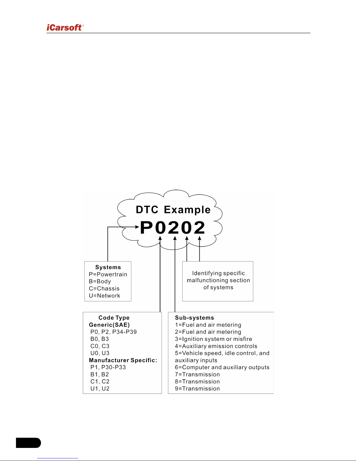
2.2 Diagnostic Trouble Codes (DTCs)..............................................................2
2.2.1 OBDII DTC..........................................................................................2
2.2.2 DTCs for J1587/J1708 and J1939......................................................3
2.3 J1708/J1587/J1939 ....................................................................................3
2.4 OBD II Denitions.......................................................................................4
3. Product Descriptions ....................................................................................6
3.1 Outline of HD I............................................................................................6
3.2 Specications .............................................................................................7
3.3 Accessories ................................................................................................7
3.4 Power supply..............................................................................................8
4. Connections & General Operations..............................................................9
4.1 Connections................................................................................................9
4.2 On-screen Buttons ...................................................................................10
4.3 Tool Setup.................................................................................................10
5. Diagnose ....................................................................................................11
5.1 HD OBD Diagnosing.................................................................................13
5.1.1 Read DTC.........................................................................................14
5.1.2 Clear DTC.........................................................................................14
5.1.3 Live Data...........................................................................................14
5.2 OBDII Diagnosing.....................................................................................15
5.2.1 Read Codes......................................................................................15
5.2.2 Erase Codes.....................................................................................16
5.2.3 I/M Readiness...................................................................................16
5.2.4 Data Stream......................................................................................17
5.2.5 View Freeze Frame ..........................................................................17
5.2.6 O2 sensor test ..................................................................................17
5.2.7 On-board monitor test.......................................................................17
5.2.8 Evap System.....................................................................................17
5.2.9 Vehicle Infomation ............................................................................17
6. How to Upgrade HD I .................................................................................18
6.1 HD I upgrading owchart..........................................................................18
6.2 User registration .......................................................................................18
6.3 Upgrading.................................................................................................19
7. FAQ ............................................................................................................20

EN
1
Heavy Duty Diagnostic Tool HD I User’s Manual
1. Introduction
The HD I is specially developed by iCarsoft for heavy duty vehicles, which
supports all 10 modes of OBDII test (EVAP, O2 Sensor, I/M Readiness, MIL
Status, VIN Info, and On-board monitors testing etc.) for a complete diagnosis
and enables users to read DTCs, clear DTCs and view the datastream with a
live color graphing. It covers a wide range of vehicles since it offers multiple
data bus protocols, such as J1587 and J1939. It can be connected to PC
through the USB cable for upgrade to keep updated with the latest software
version.
Notice: HD I may automatically reset while being disturbed by strong static
electricity. THIS IS A NORMAL REACTION.
2. General Information
2.1 On-Board Diagnostics (OBD) II
The rst generation of On-Board Diagnostics (called OBD I) was developed
by the California Air Resources Board (ARB) and implemented in 1988 to
monitor some of the emission control components on vehicles. As technology
evolved and the desire to improve the On-Board Diagnostic system increased,
a new generation of On-Board Diagnostic system was developed. This second
generation of On-Board Diagnostic regulations is called “OBD II”.
The OBD II system is designed to monitor emission control systems and
key engine components by performing either continuous or periodic tests of
specic components and vehicle conditions. When a problem is detected, the
OBD II system turns on a warning lamp (MIL) on the vehicle instrument panel
to alert the driver typically by the phrase of “Check Engine” or “Service Engine
Soon”. The system will also store important information about the detected
malfunction so that a technician can accurately nd and x the problem. Here
below follow three pieces of such valuable information:
1) Whether the Malfunction Indicator Light (MIL) is commanded ‘on’ or ‘off’;
2) Which, if any, Diagnostic Trouble Codes (DTCs) are stored;
3) Readiness Monitor status.

2
Heavy Duty Diagnostic Tool HD I User’s Manual
2.2 Diagnostic Trouble Codes (DTCs)
Diagnostic Trouble Codes (DTC) are codes that are stored by the on-board
computer diagnostic system in response to a problem found in the vehicle.
These codes identify a particular problem area and are intended to provide
you with a guide as to where a fault might be occurring within a vehicle.
2.2.1 OBDII DTC
OBD II Diagnostic Trouble Codes consist of a five-digit alphanumeric code.
The rst character, a letter, identies which control system sets the code. The
second character, a number, 0-3; other three characters, a hex character,
0-9 or A-F provide additional information on where the DTC originated and
the operating conditions that caused it to set. Here below is an example to
illustrate the structure of the digits:

EN
3
Heavy Duty Diagnostic Tool HD I User’s Manual
2.2.2 DTCs for J1587/J1708 and J1939
This section explains the basic elements of fault codes for J1587/J1708 and
J1939 data bus protocols, how to view these codes on HD I, and what they
mean. Each fault code on HD I contain three distinct pieces of information, as
described below.
J1587/J1708 fault codes consist of the following, in this order:
Subsystem Identier (SID) – Indicates what function on the ECU has failed. •
Failure Mode Indicator (FMI) – Indicates in what way the function failed.•
Occurence (OC) – Indicates the occurence times of fault codes.•
J1939 fault codes consist of the following, in this order:
Suspect Parameter Number (SPN) – Indicates what function on the ECU •
has failed.
Failure Mode Indicator (FMI) – Indicates in what way the function failed.•
Occurence (OC) – Indicates the occurence times of fault codes.•
2.3 J1708/J1587/J1939
SAE J1708, SAE J1587 and SAE J1939 are automotive diagnostic protocol
standard developed by the Society of Automotive Engineers (SAE).
SAE J1708
SAE J1708 is a standard used for serial communications between ECUs on a
heavy duty vehicle and also between a computer and the vehicle. With respect
to Open System Interconnection model (OSI), J1708 defines the physical
layer. Common higher layer protocols that operate on top of J1708 are SAE
J1587 and SAE J1922.
SAE J1587
SAE J1587 is an automotive diagnostic protocol standard developed by the
Society of Automotive Engineers (SAE) for heavy-duty and most medium-
duty vehicles built after 1985. The J1587 protocol uses different diagnostic
connectors. Up to 1995, individual OEMs used their own connectors. From
1996 to 2001, the 6-pin Deutsch-connector was standard. Beginning in 2001,
most OEMs converted to the 9-pin Deutsch. Some OEMs still use the 6-pin
Deutsch. It has mostly been used for US made vehicles, and also by Volvo.
SAE J1708 makes up the physical and data link layers while SAE J1587
makes up the transport and application layers with respect to the OSI

4
Heavy Duty Diagnostic Tool HD I User’s Manual
model. SAE J1587 is used in conjunction with SAE J1708 for automobile
communication.
SAE J1939
SAE J1939 is the vehicle bus standard used for communication and
diagnostics among vehicle components, originally by the car and heavy duty
truck industry in the United States.
SAE J1939 is used in the commercial vehicle area for communication
throughout the vehicle. With a different physical layer it is used between the
tractor and trailer. This is specied in ISO 11992.
SAE J1939 can be considered the replacement for the older SAE J1708 and
SAE J1587 specications.
SAE J1939 has been adopted widely by diesel engine manufacturers. One
driving force behind this is the increasing adoption of the engine Electronic
Control Unit (ECU), which provides one method of controlling exhaust gas
emissions within US and European standards. Consequently, SAE J1939 can
now be found in a range of diesel-powered applications: vehicles (on- and off-
road), marine propulsion, power generation and industrial pumping.
Applications of J1939 now include off-highway, truck, bus, and even some
passenger car applications.
2.4 OBD II Denitions
Powertrain Control Module (PCM) -- OBD II terminology for the on-board
computer that controls engine and drive train.
Malfunction Indicator Light (MIL) -- Malfunction Indicator Light (Service Engine
Soon, Check Engine) is a term used for the light on the instrument panel. It
is to alert the driver and/or the repair technician that there is a problem with
one or more of vehicle’s systems and may cause emissions to exceed federal
standards. If the MIL illuminates with a steady light, it indicates that a problem
has been detected and the vehicle should be serviced as soon as possible.
Under certain conditions, the dashboard light will blink or ash. This indicates
a severe problem and flashing is intended to discourage vehicle operation.
The vehicle onboard diagnostic system cannot turn the MIL off until the
necessary repairs are completed or the condition no longer exists.
DTC -- Diagnostic Trouble Codes (DTC) that identifies which section of the
emission control system has malfunctioned.
Enabling Criteria -- Also termed Enabling Conditions. They are the vehicle-
specific events or conditions that must occur within the engine before the

EN
5
Heavy Duty Diagnostic Tool HD I User’s Manual
various monitors will set, or run. Some monitors require the vehicle to follow
a prescribed “drive cycle” routine as part of the enabling criteria. Drive cycles
vary among vehicles and for each monitor in any particular vehicle. Please
refer to the vehicle’s factory service manual for specic enabling procedures.
OBD II Drive Cycle -- A specific mode of vehicle operation that provides
conditions required to set all the readiness monitors applicable to the vehicle
to the “ready” condition. The purpose of completing an OBD II drive cycle is
to force the vehicle to run its onboard diagnostics. Some form of a drive cycle
needs to be performed after DTCs have been erased from the PCM’s memory
or after the battery has been disconnected. Running through a vehicle’s
complete drive cycle will “set” the readiness monitors so that future faults can
be detected. Drive cycles vary depending on the vehicle and the monitor that
needs to be reset. For vehicle specic drive cycle, consult the service manual.
Freeze Frame Data -- When an emissions related fault occurs, the OBD
II system not only sets a code but also records a snapshot of the vehicle
operating parameters to help in identifying the problem. This set of values
is referred to as Freeze Frame Data and may include important engine
parameters such as engine RPM, vehicle speed, air flow, engine load, fuel
pressure, fuel trim value, engine coolant temperature, ignition timing advance,
or closed loop status.
Fuel Trim (FT) - Feedback adjustments to the base fuel schedule. Short-term
fuel trim refers to dynamic or instantaneous adjustments. Long-term fuel trim
refers to much more gradual adjustments to the fuel calibration schedule than
short-term trim adjustments. These long-term adjustments compensate for
vehicle differences and gradual changes that occur over time.

6
Heavy Duty Diagnostic Tool HD I User’s Manual
3. Product Descriptions
3.1 Outline of HD I
Figure 3-1
No. Name Descriptions
①Cable with OBD II
Connector
Connects the HD I to the vehicle’s Data Link
Connector (DLC).
②LCD display Indicates test results.
③button Conrms a selection (or action) from a menu
list.

EN
7
Heavy Duty Diagnostic Tool HD I User’s Manual
④/⑥ / button Move cursor up or down for selection.
⑤/⑦ / button Move cursor right or left for selection; Or
turn page up or down when more than one
page is displayed.
⑧USB port Connects to computer to update the HD I
online.
⑨button Returns to previous menu.
A Red LED indicator
lamp
DTC indicator: Once DTCs are found, it will
light up.
B Green LED indicator
lamp
No DTC indicator: When there are no DTCs,
it will light up.
C 6 pin DLC adaptor
(For vehicles with 6
pin DLC)
Connect 16 pin terminals of the adaptor
to OBD II connector, and other end to the
vehicle’s DLC.
D 9 pin DLC adaptor
(For vehicles with 9
pin DLC)
Connect 16 pin terminals of the adaptor
to OBD II connector, and other end to the
vehicle’s DLC.
3.2 Specications
Screen: 2.8” TFT 262K true color, 320*240 QVGA LCD display•
Input voltage range: 8~32V•
Operating current: <100mA@12V (Typical)•
Power consumption: < 1.2W (Typical)•
Operating temperature: 32°F~122°F / 0°C~50°C•
Storage tempetature: -4°F~158°F / -20°C ~70°C @ RH60%•
Outline dimension: 4.7’*3.2’*1.0’ / 121*82*26 mm LWH•
Weight : < 17.6 oz (500g)•
3.3 Accessories
User’s Manual -- Instructions on tool operations•
6 PIN DLC adaptor •
9 PIN DLC adaptor•
USB cable -- Connect to a computer for upgrading online •

8
Heavy Duty Diagnostic Tool HD I User’s Manual
3.4 Power supply
The power of the HD I is provided via the vehicle’s Data Link Connector
(DLC). Follow the steps below to power it up:
Find DLC on heavy duty vehicle:1.
The DLC is the connector where diagnostic code readers interface with the
vehicle’s on-board computer and usually located in the driver’s cab.
A plastic DLC cover may be found for some vehicles and you need to
remove it before plugging the 6 pin or 9 pin DLC diagnostic adaptor. If it
cannot be found, refer to the vehicle’s service manual for the location.
Plug one end of 6 pin or 9 pin DLC diagnostic adaptor into the included 2.
OBD II 16 pin connector, and connect the other end to the heavy duty
vehicle’s DLC.

EN
9
Heavy Duty Diagnostic Tool HD I User’s Manual
4. Connections & General Operations
4.1 Connections
Turn the ignition off.1.
Locate the heavy duty vehicle’s DLC. 2.
Select the desired diagnostic adaptor according to your vehicle’s DLC. 3.
Plug one end of 6pin or 9pin DLC diagnostic adaptor into the included OBD 4.
II 16 pin connector, and connect the other end to the heavy duty truck’s
DLC.
Turn the ignition on. Engine can be off or running.5.
After nishing, the system will enter the main menu interface, as shown in 6.
Figure 4-1.
Figure 4-1
Function Items Descriptions
Diagnose To diagnose your heavy-duty truck.
Tool Setup To congure the system date and time and turn on / off
the beeper.
Tool Information It mainly includes software version, hardware version,
serial number, time and date.
CAUTION: Don’t connect or disconnect any test equipment with ignition on or engine
running.

10
Heavy Duty Diagnostic Tool HD I User’s Manual
4.2 On-screen Buttons
The on-screen buttons displayed at the bottom of the screen are designed to
give a sign of which operations can be executed. If certain button turns white, it
indicates that this action is currently disabled. In case the button is highlighted
in black, you can perform the function by pressing the corresponding button on
the HD I. For detailed descriptions of buttons, please refer to Chapter 3.1.
4.3 Tool Setup
Select [Tool Setup] in the main menu and press [ ], the system will enter the
system setup screen:
1) Beeper: Turn ON/OFF the Beeper. Once Beeper is set to ON, will
appear at bottom of the screen.
2) Language: Congure the system language to your preference.
3) Time and Date: Set time and date.
Figure 4-2
Use [ ] / [ ] button to change the highlighted numbers; press [ ] / [ ] to
move the highlight bar to different position; press [ ] to conrm.
4) Unit system setting: Set the measurement unit system.

EN
11
Heavy Duty Diagnostic Tool HD I User’s Manual
5. Diagnose
In Figure 4-1, press [ ] to scan the protocols of heavy-duty trucks and OBDII
vehicles, a screen similar to gure 5-1 will appear:
Figure 5-1
If a vehicle equipped with OBDII is tested, the system will enter the function
selection screen once scanning has nished successfully.
Figure 5-2
Press [ ] to enter the system selection screen. For detailed operations,
please refer to Chapter 5.2 “OBDII Diagnosing”.
If a heavy-duty truck is diagnosed, the system will continue scanning the
protocols the truck supports and then enter the system selection screen. See
gure 5-3.

12
Heavy Duty Diagnostic Tool HD I User’s Manual
Figure 5-3
For detailed operations, please refer to Chapter 5.1 “HD OBD Diagnosing”.
If scanning failure occurs, the system will enter the screen as shown in Figure
5-4:
Figure 5-4
In this case, follow the diagnosis owchart shown as below to proceed:

EN
13
Heavy Duty Diagnostic Tool HD I User’s Manual
Figure 5-5
5.1 HD OBD Diagnosing
In Figure 5-3, use [ ] / [ ] button to select the desired system and press [ ]
to enter:
Figure 5-6

14
Heavy Duty Diagnostic Tool HD I User’s Manual
5.1.1 Read DTC
This option is used to read the current activated or historical activated trouble
codes.
Generally, there are three elements for one J1939 DTC (See Figure 5-7):
Suspect Parameter Number (SPN) – Indicates what function on the ECU •
has failed.
Failure Mode Indicator (FMI) – Indicates in what way the function failed.•
Occurence (OC) – Indicates the occurence times of the current DTC.•
Indicates there are total 8
codes and SPN0100 is the
rst code to display.
Further descriptions
on current DTC
Figure 5-7
Whereas, if we choose [J1587/1708], the fault code includes:
Subsystem Identier (SID) – Indicates what function on the ECU has failed. •
Failure Mode Indicator (FMI) – Indicates in what way the function failed.•
Occurence (OC) – Indicates the occurence times of the current DTC.•
Press [ ] / [ ] to view the next or previous trouble code; press [ ] to exit and
return to the function screen.
5.1.2 Clear DTC
This option allows you to clear the existing or historic trouble codes.
Note: After clearing, you should retrieve trouble codes once more or turn ignition on
and retrieve codes again. If there are still some trouble codes in the system, please
troubleshoot the code using a factory diagnosis guide, then clear the code and recheck.
5.1.3 Live Data
This option enables you to read the real-time data stream in character or
graphic form.

EN
15
Heavy Duty Diagnostic Tool HD I User’s Manual
Figure 5-8
A. View All Items: To view all data stream items.
B. Select Items: Select the desired data stream items, and then press [ ] to
read the value of the selected items.
C. View Graphic Items: Select the desired data stream item and press [ ] to
display it in live graphic form. (Note: Max. 1 item is supported.)
5.2 OBDII Diagnosing
Press [ ] in Figure 5-2, a screen similar to Figure 5-9 will appear:
Figure 5-9
5.2.1 Read Codes
This option is used to read the current, pending or permanent trouble codes.
If the trouble code is found, the system will display the detailed description of
the trouble code:

16
Heavy Duty Diagnostic Tool HD I User’s Manual
Figure 5-10 Figure 5-11
In Figure 5-10, 3/12 indicates there are total 12 codes and P0102 is the third
code to display.
If the DTC is dened by the manufacturer, a screen similar to Figure 5-11 will
appear. In this case, press [ ] to select the manufacturer from the list and the
screen will show the detailed content of the trouble code.
5.2.2 Erase Codes
It is used to clear all existing trouble codes.
Notes:
Before performing this function, make sure to retrieve and record the trouble•
codes.
After clearing, you should retrieve trouble codes once more or turn ignition on•
and retrieve codes again. If there are still some trouble codes in the system, please
troubleshoot the code using a factory diagnosis guide, then clear the code and
recheck.
5.2.3 I/M Readiness
I/M refers to Inspection and Maintenance that is legislated by the Government
to meet federal clean-air standards. I/M Readiness indicates whether or not
the various emissions-related systems on the vehicle are operating properly
and are ready for Inspection and Maintenance testing.
The purpose of the I/M Readiness Monitor Status is to indicate which of the
vehicle’s Monitors have run and completed their diagnosis and testing, and
which ones have not yet run and completed testing and diagnosis of their
designated sections of the vehicle’s emissions system.
The I/M Readiness Monitor Status function also can be used (after repair of
a fault has been performed) to confirm that the repair has been performed

EN
17
Heavy Duty Diagnostic Tool HD I User’s Manual
correctly, and/or to check for Monitor Run Status.
Note: N/A means not available on this vehicle; INC means incomplete or not ready
and OK means Completed or Monitor Ok.
5.2.4 Data Stream
This item enables you to view all data stream items and the live waveform of
all selected items.
5.2.5 View Freeze Frame
When an emission-related fault occurs, certain vehicle conditions are recorded
by the on-board computer. This information is referred to as freeze frame
data. Freeze Data is a snapshot of the operating conditions at the time of an
emission-related fault.
Note: If DTCs were erased, Freeze Data may not be stored in vehicle memory
depending on vehicle.
5.2.6 O2 sensor test
The results of O2 sensor test are not live values but instead the results of the
ECU’s last O2 sensor test. For live O2 sensor readings, refer to any of the live
sensor screens such as Graph Screen.
Not all test values are applicable to all vehicles. Therefore, the list generated
will vary depending on vehicle. In addition, not all vehicles support the Oxygen
Sensors screen.
5.2.7 On-board monitor test
This function can be utilized to read the results of on-board diagnostic
monitoring tests for specic components/systems.
5.2.8 Evap System
The EVAP test function lets you initiate a leak test for the vehicle’s EVAP
system. HD I does not perform the leak test, but signals to vehicle’s on-board
computer to initiate the test. Before using the system test function, refer to the
vehicle’s service repair manual to determine the procedures necessary to stop
the test.
5.2.9 Vehicle Infomation
This option allows you to view the relevant information of the vehicle, including
VIN (Vehicle identication Number), CID (Calibration ID) and CVN (Calibration
verication number).
Table of contents
Languages:
Other iCarsoft Other manuals
Popular Other manuals by other brands

Kohler
Kohler Englefield Valencia Elite installation instructions

ReelCraft
ReelCraft 5635 OLPSW5 operating instructions

AEM
AEM 21-8027 installation instructions

LAMBORGHINI
LAMBORGHINI XILO T 24 MS W-TOP - SCHEMA manual

Oculus VR
Oculus VR GO Getting started

Tennant
Tennant T5e ec-H2O 9006828 installation instructions

Harken
Harken 46 Rewind STA EL Installation and maintenance manual

Sony Ericsson
Sony Ericsson W595 Walkman Disassembly

Polargos
Polargos EASY WAY202 Assembly and service manual

Loreme
Loreme RPL23 Configuration handbook

brennenstuhl
brennenstuhl KT A92 V315 DE Instructions for use

Logik
Logik L20DH16 instruction manual