Boumatic ViewPoint 9e947c User manual
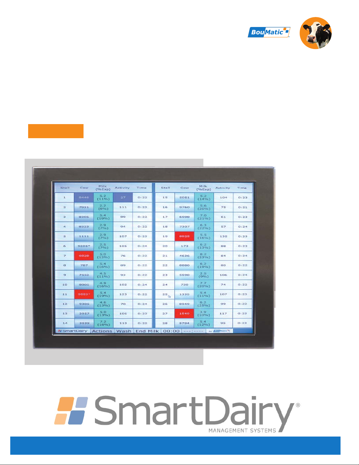
ViewPoint™ Touch Screen
9e947c
www.boumatic.com
G
e
n
t
l
y
,
Q
u
i
c
k
l
y
a
n
d
C
o
m
p
l
e
t
e
l
y
™
Installation Instructions
11/2017

ISO 5707:2007(E) Conformance
This product has been tested to and meets or exceeds the pulsation system requirements
listed in section 6 of the ISO 5707 International Standard for Milking Machine Installations –
Construction and Performance.
Installation Responsibilities and Tips
Procedures in these instructions are to be performed according to all applicable codes
(state, local, and other) by the person(s) qualified (licensed if applicable) to do so –
that is:
Any welding must be done by a qualified welder.
High Voltage AC power wiring must be done by a qualified (licensed) electrician in
compliance with the latest edition of the ANSI/NFPA Standard 70, National Electrical Code,
(USA) or either LVD 73/23/EEC or EMC 89/336/EEC (Europe) and in compliance with the
local wiring codes as applicable.
Other installation, major maintenance, and service work must be done by an authorized
BouMatic dealer.
Product/system evaluation and troubleshooting to be performed by an authorized
BouMatic dealer.
Deviation from these instructions could affect product performance or create a hazardous
situation. Under no circumstances will BouMatic be responsible for any problems caused
in whole or in part by any deviation from the procedures specified in these instructions
without prior written approval from BouMatic.
Operation steps may be performed by the owner/operator once the dealer or technician
has successfully finished the product/system evaluation. The owner/operator is responsible
for properly operating, maintaining, and monitoring the product/system to ensure that it
works properly.
Close compliance with the procedures herein is essential for the owner to get maximum
performance and benefit from this product/system.
Disclaimers
No warranties are contained in these instructions. The division of responsibilities, stated
above, is a general reminder of those provisions in the applicable dealer contract and
does not change any agreement between BouMatic and the Dealer. Information in these
instructions is not all-inclusive and cannot cover all unique situations.
MySmartDairy.com SmartDairy™ ViewPoint™ Touch Screen Installation Instructions - 9E-947C-1110 © 2017 BouMatic.

9e947c
11/24/17
3
ViewPoint Touch Screen Installation Instructions
Table of Contents
1. Safety ......................................................................................................................................... 4
1.1 Reviewing Personal Safety Messages ................................................................................... 4
2. Preparation .................................................................................................................................. 4
2.1 Verifying Part and Tool Requirements: ................................................................................ 4
2.2 Required Boumatic Components ......................................................................................... 4
2.3 Dealer Supplied Parts ........................................................................................................ 4
2.4 Special Tools .................................................................................................................... 4
2.5 Specifications ................................................................................................................... 4
2.5.1 Power......................................................................................................................... 4
2.5.2 Weight........................................................................................................................... 4
2.5.3 Temperature Rating ....................................................................................................... 4
2.5.3.1 Operational ................................................................................................................ 4
2.5.3.2 Storage and Transport ................................................................................................. 4
2.5.4 Touch Screen Dimensions ............................................................................................... 4
2.6 Calibrating the touch screen ............................................................................................... 4
3. Installation .................................................................................................................................. 5
3.1 Power Supply Installation .................................................................................................. 5
3.2 Ethernet Switch Installation ............................................................................................... 5
3.3 Wall Mounted Arm Installation ............................................................................................ 7
3.4 Floor Stand Installation ...................................................................................................... 9
3.5 Spare parts list ............................................................................................................... 10
Junction box .............................................................................................................. 10
Mount Assy, Touch Screen, Wall ................................................................................... 11
Mount assy, Touch Screen, Floor .................................................................................. 12
3.6 Assembly Instructions, Touch Screen ................................................................................ 13
4. Commissioning Checklist ............................................................................................................. 14

9e947c
11/24/17
4
ViewPoint Touch Screen Installation Instructions
1. Safety
1.1 Reviewing Personal Safety
Messages
To prevent possible bodily injury, follow the safety
messages below and throughout the booklet. Safety
should be everyone’s primary concern. By follownig
these instructions the major hazards of being pinched
or falling can be avoided. Note that the owner is re-
sponsible for replacing safety labels should they be-
come illegible.
-WARNING---------------
Keep the power turned off and lockout to the power
supply until all system wiring is completed and
inspected. Failure to do so could cause serious injury
or death.
2. Preparation
2.1 Verifying Part and Tool
Requirements:
3560986 Kit, Touch Screen, wall mount
3560987 Kit, Touch Screen, floor mount
3562637 Touch Screen sp wo engrav. logo
3562638 Touch Screen sp w.engrav.logo
3562622 Packed parts, touch screen 19"
2.2 Required Boumatic
Components
•Smart Dairy Controller
•TouchPoint, Viewpoint, or ProVantage meters
•PC Configured with Smart Dairy application
2.3 Dealer Supplied Parts
Cat 5 Ethernet Cable, and Connectors
2.4 Special Tools
•Metric Wrenches (13mm)
•3/16“ Allen Wrench
•Screw Drivers - Flat Blade, #2 Phillips
•Electrical Wire Stripper
2.5 Specifications
2.5.1 Power
Power Consumption: Typical 47W, Max 60W
Voltage: +24VDC, regulated, 20 to 28 volts
2.5.2 Weight
Touch screen: 24 lbs
Wall mount arm: 10 lbs
2.5.3 Temperature Rating
2.5.3.1 Operational
•32°F to 109°F (0°C to 43°C)
2.5.3.2 Storage and Transport
• -4°F to 140°F (-20°C to 60°C)
2.5.4 Touch Screen Dimensions
•18”W x 14½”H x 4½”D
2.6 Calibrating the touch screen
•No calibration required! If the cursor accuracy
has been lost, please contact BouMatic for
service or return the touch screen.
9e947c
11/24/17
5
ViewPoint Touch Screen Installation Instructions
3. Installation
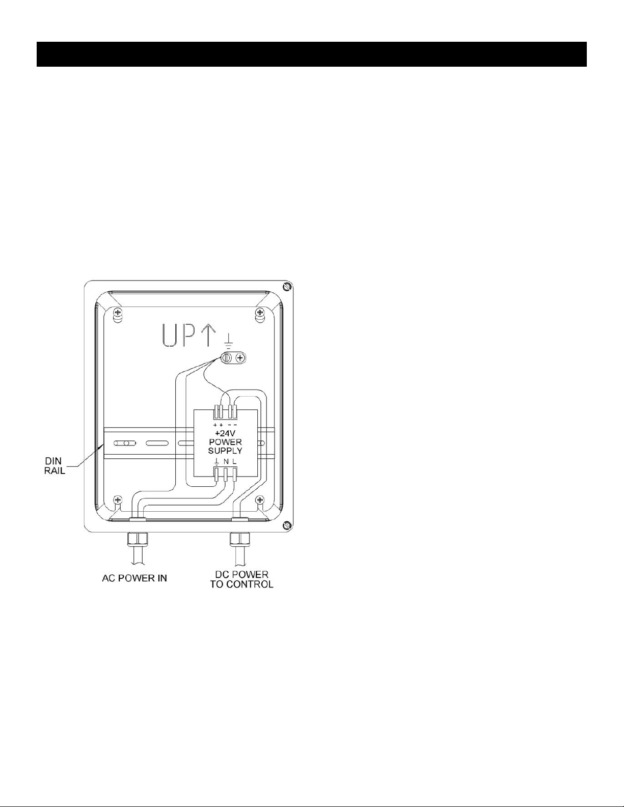
3.1 Power Supply Installation
The power supply and ethernet switch should be
mounted with the provided enclosure and located in
the parlor office near the Smart Dairy Controller. The
range for proper operation is 24VDC+/- 6.0 VDC,
(20-28 VDC). The DC common terminal of the DC
supply must be connected to earth ground, (PE) at
the DC power supply for proper operation.
To allow for voltage drops in the wiring, the DC pow-
er supplies should be adjusted to 25.5 VDC, without
any loads connected.
-NOTICE----------------------------
Do not apply DC power to the touch screen served
by the power supply until all connections have been
made between the power supply and the touch
screen. If power is applied to the touch screen before
all connections have been made, the power supply
may become overloaded, causing a circuit breaker
to trip or other power supply damage to result or
possibly causing damage to products served by the
power supply.
-NOTICE---------------------------
Main AC power supplied to DC supply enclosure may
utilize provided power cord, or for aesthetics, route
through conduit.
3.2 Ethernet Switch Installation
•Mount Ethernet switch next to DC power
supply.
•Wire connections to the power supply using
the following figures.
•Run the power and Ethernet cables from the
power supply box to the mounting location
of the touch screen arm.
•Use the supplied 2 conductor power cable PN
3559265.
•Extra strain reliefs have been provided to ac-
commodate entry to the supply enclosure.
•Use the 1/2” ID strain relief for the Ethernet
cable entry. PN 8506904 vinyl hose should
be slit open and inserted over Ethernet
cable. Insert Ethernet cable and vinyl hose
through strain relief, and hand tighten.
The AC input of the DC supply should have transient
(lightning) protection installed. The protection de-
vice should be installed as close as possible to the
DC power supply.
Figure 1: 24 VDC Power Supply

9e947c
11/24/17
6
ViewPoint Touch Screen Installation Instructions
An enclosure has been provided for the Ethernet
switch, and power supply. An Ethernet cable will be
run from the PC to the Ethernet switch. Also, an
Ethernet cable will run from the Smart Dairy
Controller to the switch. For each touch screen, an
Ethernet cable will also run to the switch.
The Ethernet switch has diagnostic lights
which indicate when the devices are
successfully connected and transmitting. The
connections can be hooked up after the
switch is wired for power and the power is
turned on.
-NOTICE-----------------------------
Maximum length for the power wires and Ethernet cable is 91m [300 ft].
Figure 3: Ethernet Switch detail
Figure 2: Power Supply wiring detail
24VDC 0VDC GND
VIEWPOINT
0VDC
VIEWPOINT
24VDC
+ - G

9e947c
11/24/17
7
ViewPoint Touch Screen Installation Instructions
3.3 Wall Mounted Arm
Installation
•Assembly Arm using the provided hardware
kit, figure 4.
Figure 4: Wall Mounting Arm Details
•Mounting the Arm: Mount the arm securely to
a wall. Fasteners must tie into the wall fram-
ing. Concrete anchors must be used if mount-
ing to a concrete wall. The holes in the mount-
ing plate are sized for a Ø3/8” [Ø10mm] bolt.
See Figure 5 for installed reference dimen-
sions.
Figure 5
•Power Supply Location: The power supply
and Ethernet switch should be mounted in-
side the provided enclosure. The power sup-
ply enclosure should then be mounted in the
parlor office near the SmartDairy controller. The
24VDC power wiring and Ethernet cable should
be routed in rigid conduit from the power sup-
ply enclosure out to the junction box in the touch
screen console. See Figure 6. Make sure to leave
extra wire for the possibility to relocate the touch
screen if necessary.
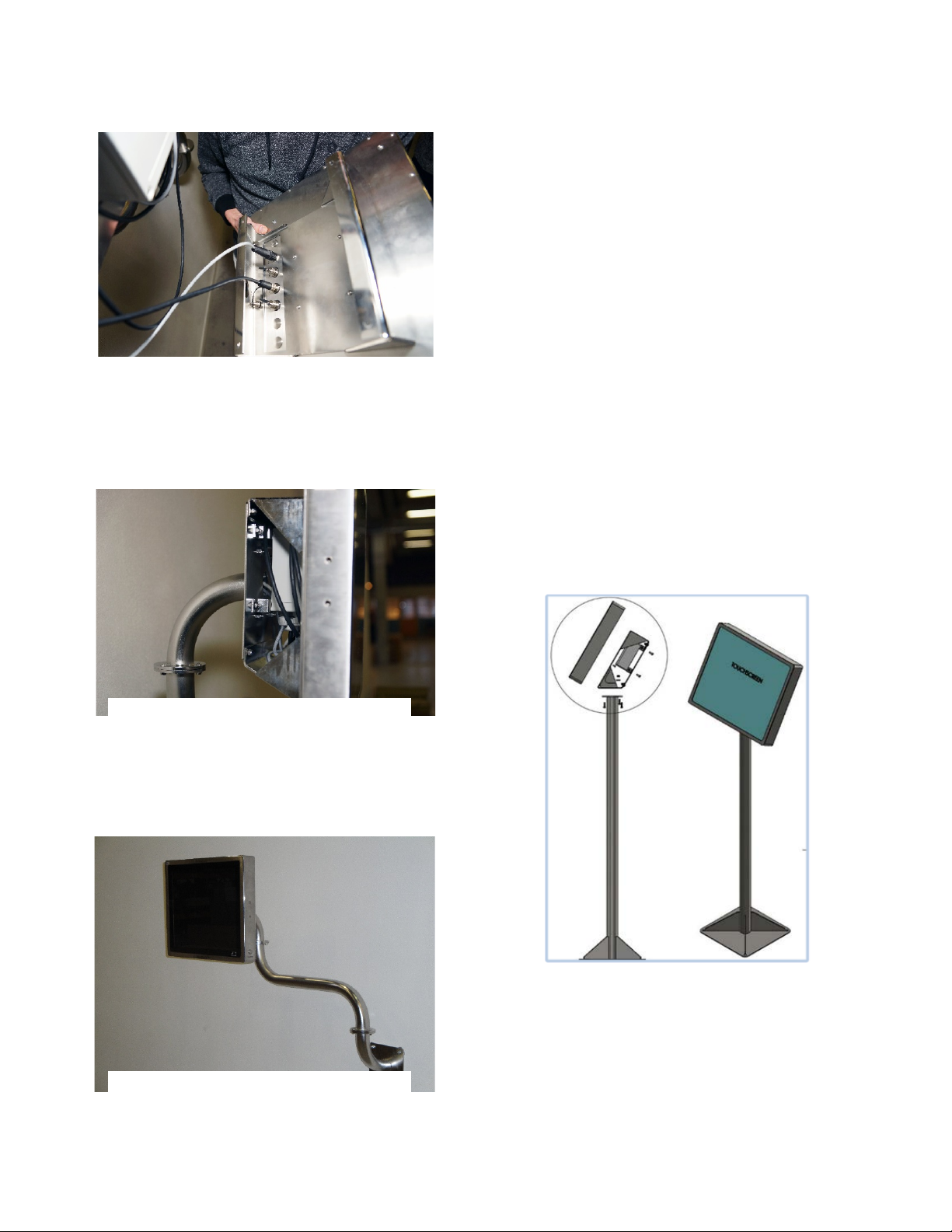
•The 24VDC power wiring and Ethernet cable
should be routed inside the arm from the power
supply enclosure out to the junction box in the
touch screen console. See figure 6.
Figure 6
•Cables installed correctly: Make sure both
the ethernet cable and the power supply
cable are ready for installation.
Figure 7: Mounting the arm on the wall

9e947c
11/24/17
8
ViewPoint Touch Screen Installation Instructions
•Install the junction box on the cover
plate for the touch screen. See Assembly
Instructions, Touch Screen for details.
Figure 8: Install the junction box
•Junction box connections: the cables
must be routed as illustrated.
Figure 9
•Mounting the power supply cable:
Mounting the 24VDC power supply cable
only in the 2 middle terminals.
Figure 10
Polarization of the 24VDC power supply unit
is indifferent because of the rectifier.
•Install the 2 ethernet cables. Make sure to
place the rubber sleeves when the nut is
tightened.
Figure 11
•Connect the ethernet cables using an
adaptor inside the junction box.
Figure 12
•Place excess cable around the junction box
before installing the console with the touch
screen.
Figure 13
9e947c
11/24/17
9
ViewPoint Touch Screen Installation Instructions
•Plug in the ethernet and the power supply
cables from the junction box.
Figure 14
•Install the touch screen and the console.
See Assembly Instructions, Touch Screen
for details.
•The wall arm mounted.
The finished installation of the wall mounted
screen.
3.4 Floor Stand Installation
The floor stand installation is nearly identical to the
wall mounted arm installation with a few exceptions.
•It is recommended to mount the floor stand
near a wall where the junction box can be
mounted.
•The floor stand will need to be anchored to
the floor instead of the wall. Appropriate
concrete anchors or lag bolts will need to be
used here.
•The suggested floor stand configuration is
shown in Figure 17.
The conduit should be routed alongside, or inside,
the floor stand post.
See Assembly Instructions, Touch Screen.
Figure 17
Figure 15
Figure 16
9e947c
11/24/17
10
ViewPoint Touch Screen Installation Instructions
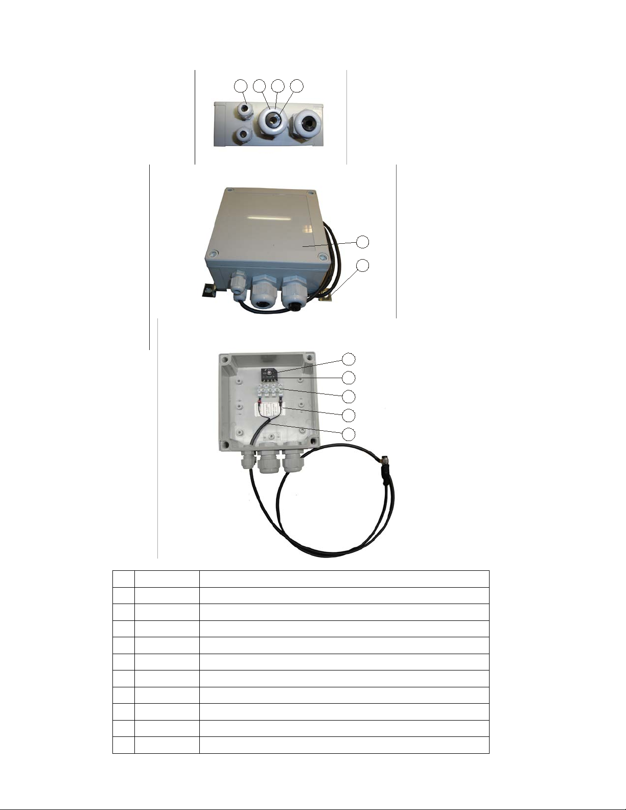
3.5 Spare parts list
Junction box
2 3 41
6
5
10
9
8
7
11
01
601229235
SCREWED CONNECTION M12 Ø1,5-5
02
601229244
SCREWED CONNECTION M25 Ø9-18
03
601229248
UNION NUT FOR M25 SCREWED CONNECTION
04
601225645
CABLE SHEATH PVC BLACK 15X0,5 MM
05
601229057
MOUNTING BOX 130X130X60 MM INCL. LID, GREY
06
608553153
BRACKET,BOX,BENT,TOUCHSCREEN
07
691776308
Ø3,5X13 SHEET-METAL SCREW W/CROSSHEAD, DIN 7981 A2
08
601225698
RECTIFIER 600V 4-KBL 6A
09
601229500
TERMINAL 2,5 MM2 12-POLED (CASTELLATED SLEEVE)
10
608553149
LABEL,TOUCHSCREEN POWER CONNECTION
11
3562623
POWER CABLE, TOUCHSCREEN
9e947c
11/24/17
11
ViewPoint Touch Screen Installation Instructions
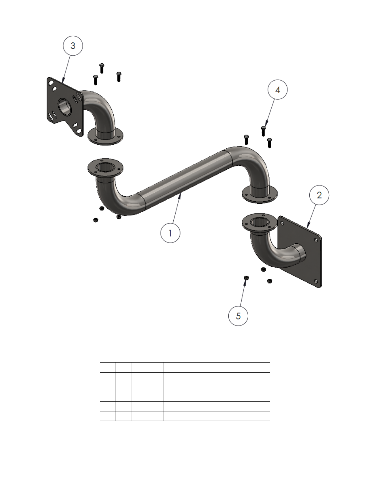
Mount Assy, Touch Screen, Wall
5 6
694070505
M6 LOCK NUT SS DIN 985-A2
4 6
690170512
M6X20 SET SCREW SS. DIN 933 A2
3 1
3562632
PIPE BEND, TOUCHSCREEN
2 1
3562634
PIPE BEND, WALL, TOUCHSCREEN
1 1
3562633
INTERMEDIATE PIPE, TOUCHSCREEN
Pos.
QTY.
Nummer
TXT
9e947c
11/24/17
12
ViewPoint Touch Screen Installation Instructions
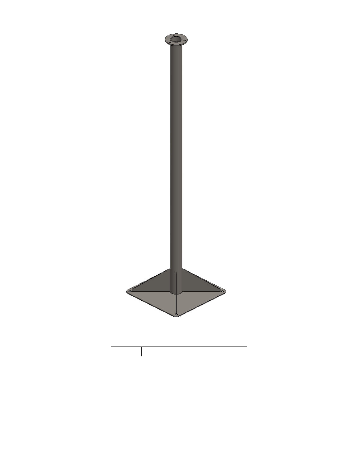
Mount assy, Touch Screen, Floor
356098 Floor Stand, Touch Screen

A
4 X M6
4 X M6
4 X M6X16mm
4 X M6X20mm
4 X Ø6
4 X M4X10mm
B
4 X M6X16mm
3 X M6
4 X M6
3 X Ø6
4 X M4X10mm
3 X M6X20mm
D
E
F
C
1
2
3
4
B
A
3
2
1
5
C
D
4
6
7
8
A
B
ASSEMBLY INSTRUCTIONS,
TOUCHSCREEN
3562639
Oct 05, 2017
EHZ
EHZ
Weight: Kg
A3
SHEET 1 OF 1
SCALE:1:20
DRAWING NUMBER
DESCRIPTION
DATE
DEBURR HOLES AND SHARP
EDGES
-ALL DIMENSIONS ARE IN
MILIMETERS
SURFACES TREATMENT
APPROVED BY
ESTABLISH BY
INT.
REV.
CHANGE
This drawing is confidential and
proprietary to BouMatic. It is loaned
strictly on condition that the
information will not be used for the
benefit of any other entity.
Telefon : +45 7526 0211
Telefax : +45 7526 0396
E-mail: [email protected]
Web: www.boumatic.com
TOLERANCE UNLESS
OTHERWISE SPECIFIED
FIRST ANGLE
PROJECTION
Revision
A
8
5
6
7
E
F
Oct 11, 2017
A
CREATED IN SW.
EHZ
APPROVED DRAWING
Jernvej 2
DK 6900 Skjern
ISO
DS/EN 22768-1 m
NON

9e947c
11/24/17
14
ViewPoint Touch Screen Installation Instructions
4. Commissioning Checklist
The items below cover the steps that need to be tak-
en to ready the product for use. The checklist will be
completed by the dealer during installation and will
become part of the complete CASE document for the
installation. The second part of the CASE program
will be a verification that the system is working to
BouMatic specifications.
ACTION
CHECKMARK
Arm/Floor mount secured properly
Power supply enclosure mounted in parlor office
Power supply voltage adjusted to 25.5 VDC
Verify power and ethernet connections
Ethernet switch has power
Screen powers up
Table of contents
 user manual")


