Bourgault XR Series User manual

(IIHFWLYH'DWHSept0RGLILHGODVWE\%+
XR750/77035('(/,9(5<,163(&7,21&+(&./,67
Date:
Dealership:
Serial #:
Model - Size:

Check off
Check off
Cart
Boom lift
Hyd lines routed neatly and identified with heat shrink
Auto locking linkage for the cable is not too tight
Ensure correct cylinders are installed
Hyd lines mounted secure c/w lock nuts
Cylinder Locations/Date Codes
CHECKED BY:
3300-50 (x2)
All paint damage has been repaired
Part Number
3/4" ubolt fasteners attaching Hitch Tube Assy to Axle Assy are torqued
to 200 ± 25 ft.lbs
Hitch jack is installed
Cable extension plates (#8600-87) are installed parallel to beam, with
one on top of the auto fold loop (#8600-86) and one on the bottom
Auto locking mechanism rotates easily with springs not attached
All grease zerks are in place and greased
Tabs on locking arms are adjusted even with hitch when in locked or
field position - add shims where necessary
Axle assembly is centered on the cart.
Wheel nuts torqued to 160 ± 15 ft.lbs
Cart
Safety chain (20200lb min) is attached
Hitch tongue is installed in correct location (holes 3+4 from bottom)
Tire pressure on cart tires is 24 ± 3 P.S.I.

Check off
Check off
Boom
Left Steering
Right Steering
Booms
Towers in proper locations
Tower bolts are tightened to 200 +/- 25 ft.lbs
Cylinder Locations
Boom Hyd
Fold cylinders plumbed neatly
Steering cylinders plumbed neatly
Boom wheel mount 8621-30 is installed in the correct orientation that allows for correct
wheel rotation and provides a rotation stop when cylinder is retracted (field position).
All paint damage has been repaired
Boom wheel bolts are torqued to 160 ± 15 ft.lbs
Boom wheel tires are inflated to 30 ± 3 P.S.I.
All grease zerks are in place and greased
Hitch jack #2090-33 is installed on both wings in correct location
Double plates on boom cable bracket positioned to the bottom of the boom on all units.
Hoses are routed across knuckles with enough slack between 8621-68 mounts to allow for
fold/unfold.
CHECKED BY:
70ft. 4340-93 - 7/8"X308" Cable Qty 2
Ensure all cylinders are in correct locations (see below)
Hyd hoses meet min bend specs - refer to attached sheet
Correct cables are installed
90ft. 4340-92 - 7/8"X408" Cable Qty 2
Ensure lock arms unlock when folding unit
3300-13
Part Number
3300-13

Check off
Check off
Boom
Left Tine Adjust
Left Tine Adjust
Left Tine Adjust
Left Tine Adjust (90')
Right Tine Adjust
Right Tine Adjust
Right Tine Adjust
Right Tine Adjust (90')
ADF
Check off
3303-36 (14 or 18)
Cylinder Locations
Part Number
3302-10 (outer)
3302-11 (Next inner)
3302-12 (Next inner)
3302-13 (Next inner)
Boom Hyd
Parallel arm cylinders plumbed neatly
Tine angle cylinders plumbed neatly
Hydraulic hoses for Tine Angle Cylinders are routed along the top of
bottom parallel arm on the tine RHS of each section and zip tied to the
chain links on the arms.
Hoses are routed across knuckles with enough slack between 8621-68
mounts to allow for fold/unfold.
3302-10 (outer)
3302-11 (Next inner)
3302-12 (Next inner)
3302-13 (Next inner)
Parallel arms are plumbed with the rod side of the cylinders connected
to the 'P' port on the block.
Safety lights installed and wired neatly
Ensure Bourgault part number decals are on all cylinders
Hyd hoses meet min bend specs - refer to attached sheet
Parallel arm cylinders plumbed so that the hoses do not twist or kink
throughout the arm range of motion.
CHECKED BY:
Decals
All decals are in the proper location as per XR-Decal
3905-70-10 decal is installed on the hitch near the coupler holder plate
All decal are in good shape and adhering properly
Decal Drawing XR-Decal is printed off and attached to the final buy-off

Check off
Slow moving sign installed.
Harrows
Tine angle indicator has been properly adjusted so the pointer remains
over the decal throughout the full range of motion. Linkage bolts are not
fully tightened so the linkages do not bind.
Tine holder 8621-59 is installed on the front inside corner of the both
RHS and LHS outermost sections to prevent the tine from interfering
with the boom wheel pivot in transport position.
All parallel arm pins are installed with the heads towards the center of
each section, and the retention bolts are installed.
All paint damage has been repaired
Final Inspection Check off
Paint touch ups complete
No hydraulic leaks
Transport circuit with sequence valve is functioning properly. During
fold-up, transport cylinders fully retract before boom wheels turn.
During unfold, boom wheels turn completely before transport cylinders
extend. (Sequence valve may need to be adjusted for different tractors)
Tine angle circuit is functioning properly. Cylinders on all sections
extend and retract evenly.
Operators manual is with machine.
Cable wing stop assembly is installed so that the cable is tight
diagonally across the sections and all the slack is between sections
behind the knuckle.
Ensure safety lights function correctly - Left & Right signals work correctly
locking arms lock when unfolding the unit
Preform fold/unfold. (see Sequence valve adjustment on following
pages or Operators manual if adjustment is needed)
CHECKED BY:
IMPORTANT: Initial hydraulic pressure of the tractor will need to be
2900 psi or higher for sequencing to occur properly. IF harrows do not
fully raise make sure tractor has at least 2900 psi before adjusting the
sequence valve.


XR Series eXtended Range Harrow Transport
5.3
5.2 Transport Sequence Valve
This harrow bar is equipped with rotatable wing
boom wheels that are used for both field and
transport orientations. The rotation also provides
the operator with a method to steer the wings
outward during unfolding for easier, quicker, and
more compact unfolding.
The wing boom wheel cylinders and transport
lift cylinders are on the same hydraulic circuit,
controlled by a sequence valve. The sequence
valve ensures the correct order when folding or
unfolding the unit:
1. During fold, the transport lift cylinders must
retract fully (lift the bar) before the wing boom
wheels can turn into transport position.
2. During unfold the wing boom wheels must
turn fully into field position before the
transport lift cylinders can extend to lower the
bar.
Figure 5.25 Wing Boom Wheel in Field Position
boomwhlfieldpos.jpg
Figure 5.26 Wing Boom Wheel in Transport Position
boomwhltranspos.jpg

XR Series eXtended Range Harrow
Transport
5.4
5.2.1 Adjusting the sequence valves
In the scenario that the transport circuit is not
sequenced properly, the valves can be adjusted
to correct the problem. The transport hydraulic
manifold is located on the harrow cart and contains
2 sequence valves, one for folding and one for
unfolding. Use the table below to determine the
required adjustment.
To adjust the sequence valves:
1. Locate the correct valve as per the table .
2. Remove the plastic cap from the end of the
valve to expose the adjustment screw.
3. Loosen the 9/16” locking nut on the valve.
4. Turn the 5/32” hex socket screw clockwise
(in) to increase the valve pressure or counter-
clockwise (out) to decrease the valve pressure.
Turn only ½ of a revolution at a time.
5. Re-check the function of the valves after every
½ turn.
6. Once properly adjusted, tighten locking nut and
return plastic cap to protect threads.
Operation Problem Solution
Fold Wing boom wheels turn before bar is fully raised Increase pressure of SCCA valve
Wing boom wheels don’t turn or turn excessively slow Decrease pressure of SCCA valve
Unfold Bar lowers before wing boom wheels are fully turned Increase pressure of SCEA valve
Bar won’t lower or lowers excessively slow Decrease pressure of SCEA valve
Figure 5.27 Transport Hydraulic Manifold
transhydmanf3.jpg

XR Series eXtended Range Harrow Trouble Shooting
7.1
7 Troubleshooting
troubleshooting.pdf
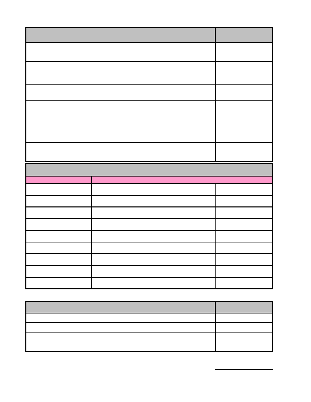
Symptom Probable Cause Solution
Cannot adjust tine angle to a more
aggressive position Too much draft force on the tines
Temporarily reduce ADF pressure or
stop harrowing. Adjust as required.
Return to previous settings.
Tine angle is uneven from section
to section Tine angle hydraulics are out of phase
Rephase tine angle hydraulics by
extending tine angle cylinders and hold
remote for several seconds before
readjusting.
Boom wheel lock valve is closed Open boom wheel lock valve.
Sequence valve is not adjusted properly See section 5.2.1 for adjustment
instructions
Transport lock pins are still in place Remove transport lock pins
Sequence valve is not adjusted properly See section 5.2.1 for adjustment
instructions
Wing booms are too far forward
compared to the cart.
Drive forward until boom will begin to
fold down. If auto-fold arms come out
of latches, tip boom down only slightly
then drive backward before continuing
to unfold.
Auto-fold lataches do not engage
over the auto-fold arms when
putting unit into field position
Auto-fold arm is set at improper angle
Adjust the angle by adding or removing
shim plate behind the arm pivot
mounting plate.
Auto-fold arms become
disengaged when adjusting the
main transport lift
The transport latches will disengage auto-
fold arms when wings are lifted.
Move the transport latch cable from the
bottom hole to the top hole on the
center boom prior to operaton. Refer to
section 4.10.3.
Cable in windrow position. Move cable position. Refer to section
4.10.3.
Excessive stretch in cable. Adjust cable length.
Transport fold or unfold happens
out of sequence
Boom will not fold down out of
transport position
Auto-fold arms do not disengage
when put into transport position

XR Series eXtended Range HarrowHydraulics
9.2
9.1 Schematics
9.1.1 Transport Circuit

XR Series eXtended Range HarrowHydraulics
9.6
9.2 Transport Sequence Manifold
The transport sequence manifold combines the
functions of the transport lift cylinders and the
wing boom wheel cylinders and forces the two
functions to occur in the correct order during fold
or unfold. This eliminates the chance for incorrect
order that would cause damage to the machine.
The valves within this manifold can be adjusted
as per Section 5.2.1, or changed out if they are
malfunctioning.
9.2.1 Fold Sequence Cartridge
The cartridge labeled SCCA is necessary for
machine fold. It forces the transport lift cylinders
to retract fully before the boom wheels can be
turned into field position.
9.2.2 Unfold Sequence Cartridge
The cartridge labeled SCEA is necessary for
machine unfold. It forces the wing boom wheels
to turn fully into field position before the transport
lift cylinders can lower the bar.
9.2.3 Check Valve Cartridge
The CKEB pilot operated check valve is an added
measure to ensure proper sequencing during
unfolds. The machine can sometimes be oriented
such that there is a tensile load on the transport
lift cylinders. The check valve locks oil to the rod
side until the SCEA sequence valve opens allowing
the check valve to pilot open as well.
This manual suits for next models
2
Table of contents
Other Bourgault Farm Equipment manuals