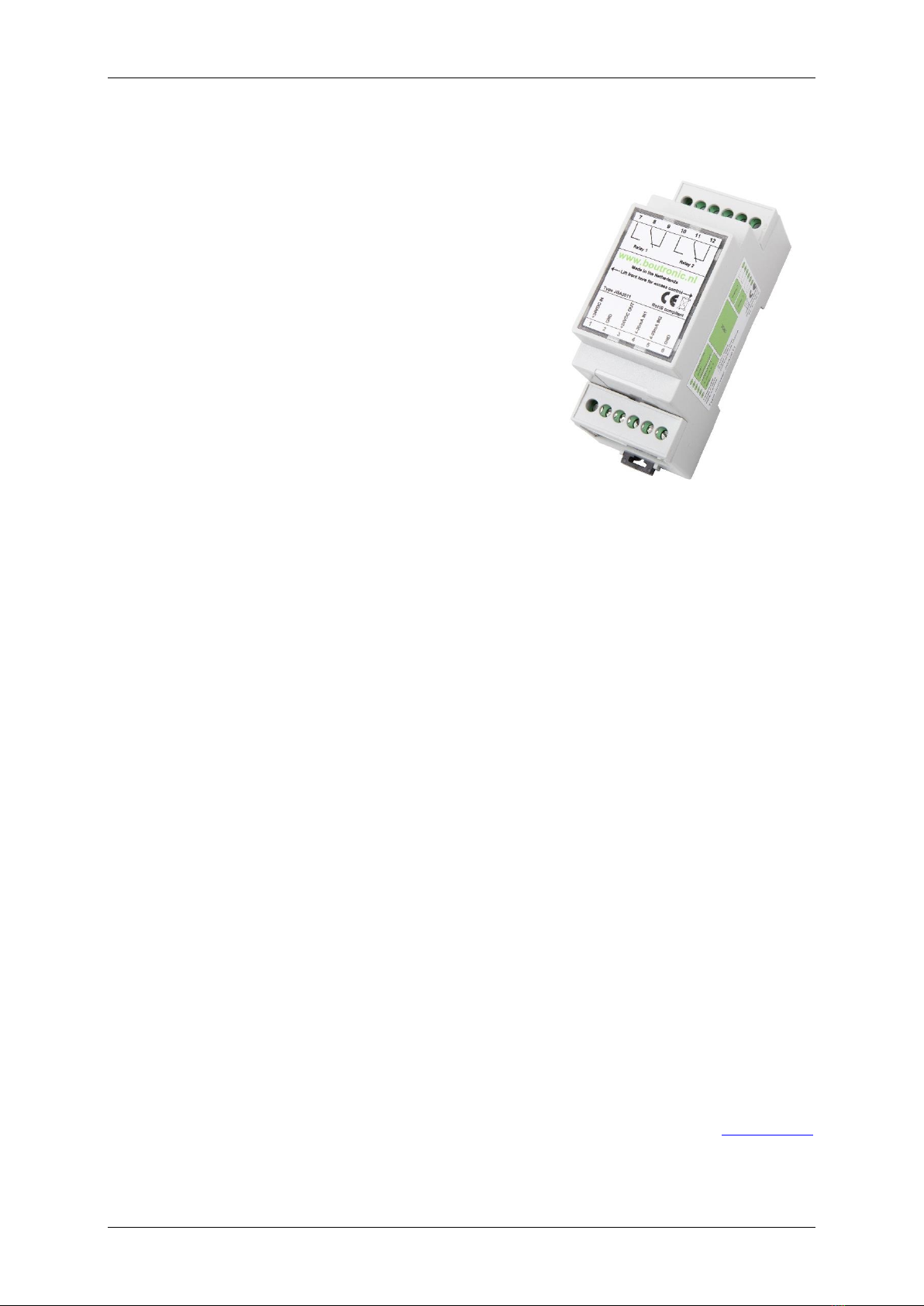
Manual Current relay print JGA2011 Boutronic B.V.
Boutronic B.V. Page - 2 - ’s-Gravenzande The Netherlands
Menu
Intro ................................................................................................................................. 1
Liability and warranty....................................................................................................... 1
Menu................................................................................................................................ 2
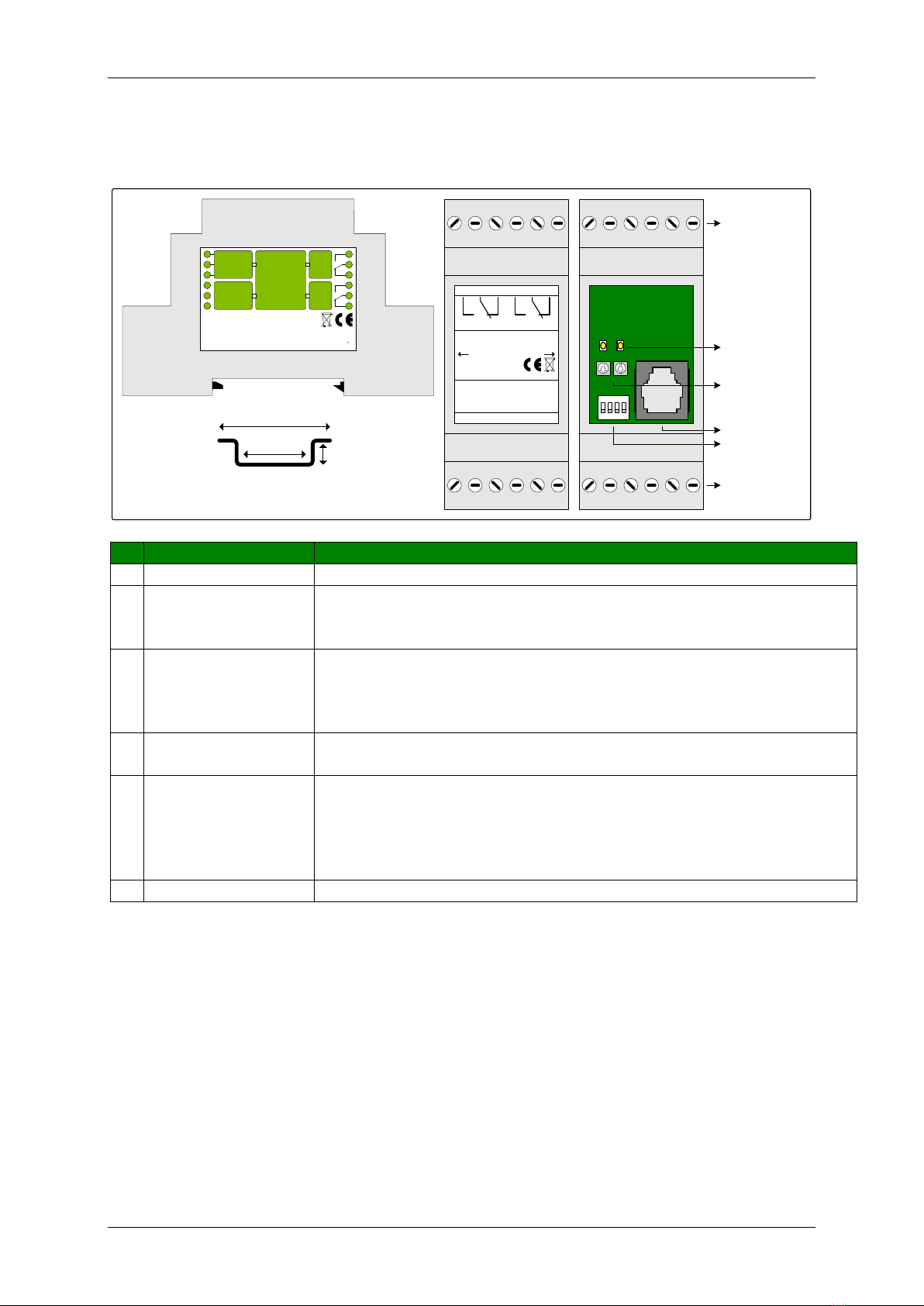
Connections...................................................................................................................... 3
Connection example............................................................................................................................ 4
Operation............................................................................................................................................. 4
Current inputs...................................................................................................................................... 4
Potentiometer ..................................................................................................................................... 5
Relay .................................................................................................................................................... 5
Switching delay Relay .......................................................................................................................... 5
Change settings ................................................................................................................ 6
Potentiometer.................................................................................................................. 6
DIP-switches..................................................................................................................... 6
Setting with the serial menu ............................................................................................. 6
Relay 1.............................................................................................................................................. 7
Relay 2.............................................................................................................................................. 7
Debug level....................................................................................................................................... 7
Factory defaults................................................................................................................................ 7
Factory test ...................................................................................................................................... 7
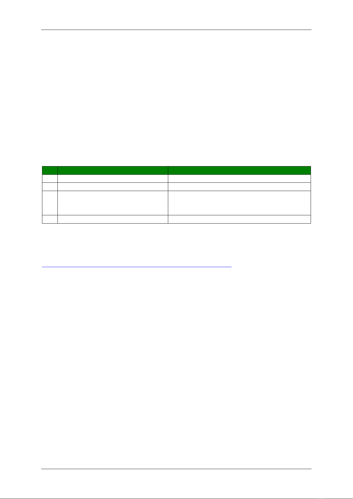
Technical specifications..................................................................................................... 8
General ................................................................................................................................................ 8
Power................................................................................................................................................... 8
Inputs................................................................................................................................................... 8
Current input.................................................................................................................................... 8
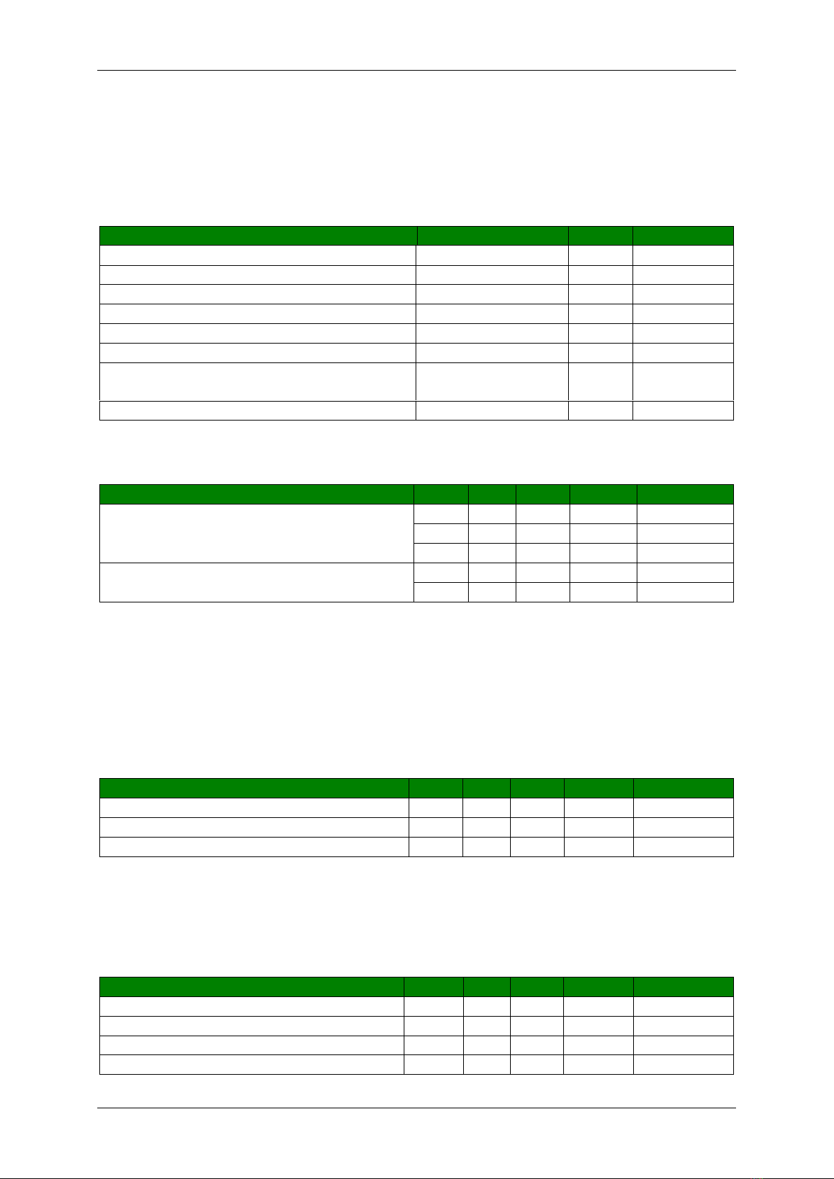
Outputs................................................................................................................................................ 8
Relay................................................................................................................................................. 8
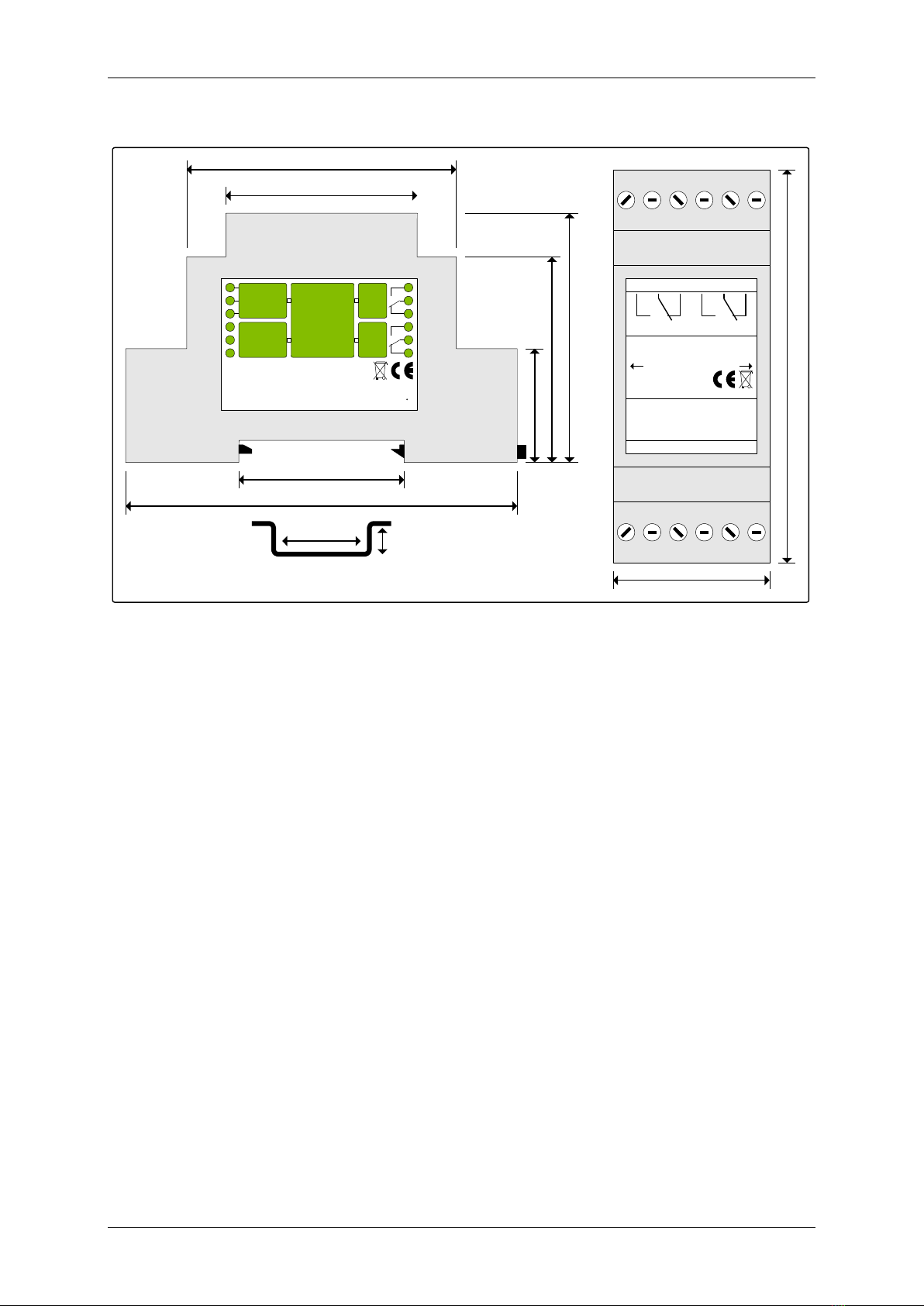
Measurements ................................................................................................................. 9