Bouyer GXT 4000-16 Configuration guide

1
DESCRIPTION
The GXT 4000 microphone console is a touch screen console. It has from 16 up to 64 programmable soft
keys for making PA broadcasts into selected areas or zones. It is designed to operate over a bus architecture,
meaning that several consoles can be used over the same network, while collectively occupying just one single
audio channel. In fact, the consoles are self-regulating, with audio channel priority always being given to the first
console that picks up the channel. The main part of the console may be flush fitted or mounted on its own swivel
base for tabletop use.
The GXT 4000 console comes complete with:
•
an electret microphone,
•
a touch screen for setting and selecting zones,
•
a memory card reader for broadcasting pre-recorded messages,
•
a loudspeaker for monitoring announcements, etc.,
•
a fail soft switch with protective hood.
It may be used to:
•
view the degree of occupancy of the network’s zones,
•
broadcast an announcement into one or more zones.
2
TECHNICAL SPECIFICATIONS
Audio signal bus:
•
Output: via transformer
•
Nominal level: 0 dBu
•
Microphone preamplifier: compressor fitted
Transmission and commands
•
Serial link: RS485 bus
User interface
•
Touch screen with up to 64 programmable soft keys and 5 function keys
•
Zone occupancy indicator
•
Audio bus occupancy indicator
•
Indicator showing whether the serial link is connected to the host system
•
a protected fail soft pushbutton switch (connector output with connection box)
•
monitoring loudspeaker
•
message memory card reader
Message memory card reader
•
Memory medium: SD card using FAT32, files stored in root directory only (sub-directories are
not supported)
•
Message format: wav, 44100 Hz, 16 bit, mono
•
The console has 2 memory card slots, one inside the console, the second accessible from the
outside. The external reader has priority
Code 596652eng–01/2024
GXT
4000
–
16
GXT
4000
–
32
GXT
4000
–
48
GXT
4000
–
64
TOUCH SCREEN
MICROPHONE
CONSOLES
GENERAL INFORMATION
Code 596652eng-01/2024

2
GXT 4000
Power
•
Voltage: 24 V d.c. (min. 12 volts, max. 28 volts)
•
Current: 110 mA (190 mA at 12 V, 100 mA at 28 V)
Housing
•
Material: metal
•
Colour: grey console on black base
•
Dimensions: 287 x 237 x 73 mm
•
Microphone overall length: 36 cm
•
Weight: 2.5 kg
•
comes complete with 2 mounting brackets and 2 screws for flush mounting
The console may be powered directly using the RJ45 sockets (refer to § 4.1 concerning restrictions). In the
case of remote consoles, however, the bus may be powered using the jack socket.
RJ45 pinout
3
PRESENTATION
View from above:
(1)
Electret microphone
(2)
Touch screen
(3)
Memory card slot
(4)
Protected fail soft pushbutton
(5)
Monitoring loudspeaker
(6)
Stylus holder
View from below:
(7)
Protected pushbutton connector cable grommet
(8)
Earth terminal
(9)
RJ45 In/Out sockets
Side view:
(10)
24 V power socket
- +
(11)
Sub-D 9 pin (RS232) serial socket for uploading
programs
4
INSTALLATION
Warning!
This appliance must not be immersed in water or otherwise subject to splashing
Pin N°
In / Out
1
Audio Out +
2
Audio Out -
3
Audio In +
4
Audio In -
5
0 V
6
+24 V
7
RS485 Data +
8
RS485 Data -

3
GXT 4000
Recess mounting
Recess dimensions: 240 x 150 mm
Separate the central unit from its base by extracting the 2 screws and brackets located underneath the unit.
Use the brackets to fix the unit to a supporting surface that has a depth of between 1 and 35 mm.
For greater depths, use spacers, wedges or longer bracket retaining screws.
Warning: when recessing, the power supply jack socket will only be accessible if the thickness of the mounting
surface is 25 mm or less. Should the recess depth exceed this, the console should be powered using the
RJ45 sockets.
4.1 General Data –Operational Limits
Number of consoles
The number of consoles that can be connected to the same bus depends on the type of installation used.
Power
A single power supply can be used to power several GXT 4000 consoles.
The table below gives an indication of power delivery limitations according to the number of consoles and
distances between them.
Number of
consoles
Distance between the power supply source and
the farthest console
3
100 m
1
150 m max.
Data calculated using the optional power supply NS110557 (24 V d.c., 500 mA) and a cable impedance of
0.085 ohm.m-1. In order to work, the absolute minimum voltage arriving at the power input terminals of each
console must be 12 V with maximum load applied.
Cabling
Consoles on the same bus are daisy-chained together at the RJ45 inputs/outputs using the cables supplied.
Over long distances, an EL720 connector box may be necessary. For audio and RS485, twisted pairs are
recommended. Electrical interference (audio parasites) may be minimised by screening the audio connectors.
Following these guidelines, the total cable length can reach 1000 m all buses combined (the limit normally
associated with RS485 networks where no repeaters are used).
EL720 connector box pinout
RJ45/8 pin terminal correspondence chart
RJ45 pinout
8 pin terminal pinout
1
8
2
7
3
6
4
5
5
4
6
3
7
2
8
1

4
GXT 4000
Fail soft mode:
To wire up the fail soft, connect the connection box (PGM) to the 26 pin connector strip located inside the
console. The connector strip may be accessed by removing the cover on the console’s base.
There is one configuration switch per protected pushbutton located on the main board inside the console; use
these switches to set the contacts to NO (normally open) or NC (normally closed) as required.
For each of the four optional pushbuttons, the indicator lamp is driven by zeroing the associated control point.
PGM connector box pinout
5
APPLICATION
5.1
Use with a CS 2500 Central Monitoring Unit as a public safety announcement system
When connected to a CS 2500 central monitoring unit, the GXT 4000 can be used to broadcast safety
announcements within selected zones; its in-built touch screen does away with any need for separate switch
matrices, thus keeping costs and cabling to a minimum. Other PA sources such as piped music, etc., may be
connected either to the CS 2500’s AUX input or to the 0 dB inputs of CS 2003 audio matrices.
IMPORTANT: Ensure that the CS 2500’s software version is version V4.50 or greater.
26 pin connector/terminal correspondence chart
26 pin connector
pinout
Terminal pinout
26 pin
connector
pinout
Terminal pinout
1
Audio In + (monitoring)
14
Contact 2 optional pushbutton 1 (NO)
2
Audio In - (monitoring)
15
Contact 2 optional pushbutton 1
(ground)
3
Audio Out + (audio fail soft mode)
16
Indicator control optional pushbutton 1
(-)
4
Audio Out - (audio fail soft mode)
17
Contact 1 optional pushbutton 4
(NO or NC)
5
Fail soft contact (NO or NC)
18
Contact 1 optional pushbutton 4
(ground)
6
Fail soft contact (ground)
19
Contact 2 optional pushbutton 4 (NO)
7
Contact 1 optional pushbutton 2 (NO
or NC)
20
Contact 2 optional pushbutton 4
(ground)
8
Contact 1 optional pushbutton 2
(ground)
21
Indicator control optional pushbutton 4
(-)
9
Contact 2 optional pushbutton 2 (NO)
22
Contact 1 optional pushbutton 3
(NO or NC)
10
Contact 2 optional pushbutton 2
(ground)
23
Contact 1 optional pushbutton 3
(ground)
11
Indicator control optional pushbutton 2
(-)
24
Contact 2 optional pushbutton 3 (NO)
12
Contact 1 optional pushbutton 1
(NO or NC)
25
Contact 2 optional pushbutton 3
(ground)
13
Contact 1 optional pushbutton 1
(ground)
26
Indicator control optional pushbutton 3
(-)

5
GXT 4000
Installation: Refer to the GXT 4000 Operator Manual
The CS 2500 has 3 separate audio buses:
•
audio bus GX1 (GX 2500 Control/Audio 1 RJ45 socket) to which can be connected either a
GX 2500 or one or more GXT 4000 or GX 3016 units (address 1);
•
audio bus GX2 (GX 2500 Control/Audio 2 RJ45 socket) to which can be connected either a
GX 2500 or one or more GXT 4000 or GX 3016 units (address 2);
•
audio bus AUX (AUX XLR socket) to which can be connected either a 0 dB source or one or
more GXT 4000 or GX 3016 units (address 3).
The maximum number of GXT 4000 units that are capable of being connected to a network may be
calculated as follows:
No. of GXT 4000 ≤ 50 - No. of CS 2500 –No. of CS 2003 –No. of GX 2500 –No. of GX 3016
5.2
Use with a CC 3816
The CC 3816 matrix has two special inputs for connecting two GXT 4000 or GX 3016 console buses
together.
Installation: Refer to the GXT 4000 Operator Manual
The CC 3816 has 2 separate audio buses:
•
audio bus 1 (Console 1 RJ45 socket) to which can be connected one or more GXT 4000 or
GX 3016 units (address 1);
•
audio bus 2 (Console 2 RJ45 socket) to which can be connected one or more GXT 4000 or
GX 3016 units (address 2).
Refer to the CC 3816 Manual for additional information.
5.3
Use with the DN 3816 (multi-DN application)
Contact Bouyer for further information.

6
GXT 4000
6
OPERATION
6.1
Description of the touch screens
6.1.1
Start screen
When first switching on the console, a Welcome screen is displayed while the
console boots up.
6.1.2
The zone selection screens
The zone selection screens are then displayed.
The GXT 4000 can be set to display its screens in either of two ways.
Display mode 1: (Standby)
This mode displays:
-
the date and time,
-
which zones are occupied,
-
the host system connection (in this case the RS485 connection has not been
established as shown by the icon ),
-
the first 16 programmable soft keys, with any remaining groups of soft keys
(up to 64 according to the version) being accessible using the bottom right
hand slider bar,
-
5 function keys (Cancel , General Announcement , Play
message , Microphone announcement and Chime ),
-
and a MENU key to access the console’s configuration menu.
Display mode 1: (ON)
This mode displays:
-
the date and time,
-
which zones are occupied (in this case the “North Entrance” zone which has
been set to soft key n°21),
-
the host system connection (in this case the RS485 connection has been
established as shown by the icon ),
-
programmable soft key numbers 17 to 32, here showing that zone 21 is
occupied,
-
and the function keys (in this example the Microphone announcement key
shows that an announcement is currently being made over the system using
the microphone).
Display mode 2 : (Standby)
This mode displays:
-
the host system connection (in this case the RS485 connection has not been
established as shown by the icon ),
-
the date and time,
-
which zones are occupied,
-
the first 10 programmable soft keys, with any remaining groups of soft keys
(up to 64 according to the version) being accessible using the right hand slider
bar,
-
5 function keys (Cancel , General Announcement , Play
message , Microphone announcement and Chime ),
-
and a MENU key to access the console’s configuration menu.

7
GXT 4000
Display mode 2 : (ON)
This mode displays:
-
the host system connection (in this case the RS485 connection has been
established as shown by the icon ),
-
the date and time,
-
which zones are occupied (in this case the “North Entrance” zone which has
been set to soft key n°21),
-
the programmable soft keys from n°17 to 26, and here showing that zone 21
is occupied,
-
and the function keys (the Microphone announcement key shows that an
announcement is currently being made over the system using the
microphone).
Pressing the Broadcast Message key opens the Broadcast Message
window. This screen is used to select a message from the memory card; once
selected it may be broadcast by pressing Play , stopped by pressing Stop
(the same key has both functions), or the user may exit this screen by
pressing .
The progress bar shows how far through the announcement the playback is.
This window is also present in display mode n°1.
6.1.3
The Configuration menu
In both display modes 1 and 2, pressing the MENU key opens a window
containing seven configuration sub-menus:
- Volume: for adjusting the microphone, chime and monitoring
loudspeaker volumes,
- Keys: for programming the touch screen’s soft keys 1 to 64 as well as
the General Announcement key,
-
Date: for adjusting the date and time,
-
Console: for changing the console’s configuration (contrast, time out,
password, ID lock, chime, announcement mode, display, language and audible
key presses),
- Message: for listing and listening to messages stored on the memory
card prior to broadcasting them,
- System: for setting system connection parameters (host system, serial
link address),
- Version: provides a summary of the essential information concerning
the console including the current software version number.
The console will return back to the zone selection screen after 20 seconds of
inactivity or by pressing the screen next to one of the menu icons.
6.1.4
The VOLUME Menu
The MIC Tab
The first tab is used to adjust the microphone volume.
Use the cursor to adjust the volume from 0 (silent) and 10 (maximum).
Pressing the Default Setting key adjusts the setting automatically
to 5.

8
GXT 4000
The CHIME Tab
The second tab is used to set the chime volume.
Use the cursor to adjust the volume from 0 (silent) and 10 (maximum).
This slider also sets the volume at which audio messages stored on the
memory card are broadcast.
Pressing the Default Setting key sets the volume automatically to 5.
The LOUDSPEAKER Tab
The third tab is used to adjust the monitoring loudspeaker volume.
Use the cursor to adjust the volume from 0 (silent) and 10 (maximum).
Pressing the Default Setting key sets the loudspeaker volume to 5.
The Mute key is used to switch the loudspeaker on or off .
Press the key to save any changes you have made in the VOLUME menu and exit.
Press the key to exit the menu without saving any changes you may have made.
Warning: After 20 seconds of inactivity the console will return back to the zone selection screen and any changes you
may have made will be discarded.
6.1.5
The KEY Menu
Access to the programming menu is password-protected; the 4 character
password must be entered using the keyboard.
The password is left empty by default (input either 4 spaces or leave blank).
Press the key to confirm the password and access the Console menu.
Should an error occur, the screen defaults back to the zone selection screen.
Press the key to return straight away to the zone selection screen.
The console will in any case automatically return back to the zone selection
screen after 20 seconds of inactivity.
The soft key programming screen shows:
-
the soft key that is being configured (in this case SOFT KEY Number 01).
The keys at the bottom of the screen may be used to scroll through the soft
keys. The same keys can be used to scroll through the programs for soft keys
1 through 64 (according to the console model) and the General Announcement
soft key.
-
Key: shows the function associated with the soft key. There are three
possible options:
•
None: the soft key has either not been programmed or is not intended
for switching a zone or group of zones,
•
Number: a key number is assigned to the soft key. Depending on how
it has been configured, the host system will make the link between
the key number and the zone or group of zones to switch,
•
General Announcement: assigns the general announcement function
to the soft key.
If the Number function is selected, a new selection zone is displayed to
choose the key number;
-
Label: provides the descriptive text - up a 16 characters –that will appear on
the soft key in the zone selection screen;
-
Message: links the broadcasting of a particular message located on the
memory card to a soft key:

9
GXT 4000
•
Where a key’s function is set to None, pressing the soft key will result
in the message being broadcast in all the previously switched zones
(the message will only play if 1 or more zones has been switched),
•
Where the key’s function is set to Number or General Announcement,
pressing the soft key will first request the zone or group linked to the
key number to be switched before it can broadcast the message.
-
: scroll down 5 at a time through the numbered soft keys,
-
: scroll down 1 at a time through the numbered soft keys,
-
: clear the program for an individual soft key or for all the soft keys,
-
: scroll up 1 at a time through the numbered soft keys,
-
: scroll up 5 at a time through the numbered soft keys.
Press Play to listen to the selected message on the monitoring
loudspeaker. Use the slider bar on the right to adjust the monitoring volume
prior to playing the message.
Press the key to save any changes you have made in the KEY menu
and exit.
Press the key to exit the menu without saving any changes you may
have made.
The console will in any case automatically return back to the zone selection
screen after 20 seconds of inactivity.
Pressing on any of the Key function, Key number or Message boxes displays a selection dial as shown above.
Pressing the Label box displays a new selection screen.
Use the keyboard to assign a name consisting of up to 16 characters to the
soft key being configured.
Press the key to save the name entered, exit the label input screen and
return back to the soft key programming screen.
Press the key to exit the label input screen and return back to the soft
key programming screen without saving any of the changes made.
Warning: After 20 seconds of inactivity the console will return back to the zone
selection screen and any changes you may have made will be discarded.
Pressing the Play key opens the Broadcast message window so that the
message can be listened to locally on the monitoring loudspeaker. This screen
allows the operator to view playback progress of the message selected and to
stop playback by pressing Stop .
The progress bar shows how far through the announcement the playback is.

10
GXT 4000
6.1.6
The DATE Menu
Warning:
−
If the console is left switched off for more than 15 days, the programmed date and time will be erased
from memory.
−
The console’s date and time settings are independent of and not synchronised to the host system.
Use the DATE/TIME menu to set the time, day and date.
Press the Time box to display the cursor under the first digit (the hour tens
digit). Use the keypad to then enter the time in the format hh:mm. The cursor
will switch automatically from one digit to the next with each key press.
The date is displayed using the following format: DD/MM/YYYY.
Press the Date box to have the cursor appear under the first digit (the day tens
digit). Use the keypad to then enter the day, month and then year. The cursor
will switch automatically from one digit to the next with each key press.
Pressing on the Day box displays a selection dial showing the days of the
week.
Using the selection dial: Values may be changed by flicking the relevant box to scroll through the various possible
options. The dial will automatically disappear, saving the selection, if the touch screen is then left alone.
Press the key to save any changes you have made in the menu and exit.
Press the key to exit the menu without saving any changes you may have made.
Warning: After 20 seconds of inactivity the console will return back to the zone selection screen and any changes you
may have made will be discarded.
Using the selection dial: Values may be changed by “flicking” the relevant box to scroll through the various possible
options. The dial will automatically disappear, saving the selection, if the touch screen is then left alone.
Press the
Press the
key to save any changes you have made in the KEY menu and exit.
key to exit the menu without saving any changes you may have made.
The console will in any case automatically return back to the zone selection screen after 20 seconds of inactivity.

11
GXT 4000
6.1.7
The CONSOLE Menu
Access to the Console programming menu is password-protected; the 4
character password must be entered using the keyboard.
The password is left empty by default (input either 4 spaces or leave blank).
Press the key to confirm the password and access the Console menu.
Should an error occur, the screen defaults back to the zone selection screen.
Press the key to go back to the zone selection screen.
The console will in any case automatically return back to the zone selection
screen after 20 seconds of inactivity.
The CONTRAST Tab
The first tab is used to adjust the screen contrast.
Use the cursor to adjust the contrast from 0 (lowest) and 10 (greatest).
Pressing the Default Setting key sets the contrast automatically to
5.
The TIME OUT Tab
The second tab is used to set the Time Out value. The Time Out value
corresponds to the period of console inactivity before the console menus
return to the Select zone screen. The Time Out range is from 2 seconds to
5 minutes (2 s, 4 s, 6 s, 8 s, 10 s, 20 s, 30 s, 40 s, 50 s, 60 s, 90 s, 2 min, 2
min 30 s, 3 min, 3 min 30 s, 4 min, 4 min 30 s, 5 min).
Pressing the Default Setting key adjusts the setting automatically to
20 seconds.
Pressing on the Time Out box displays the possible Time Out values.
The PASSWORD Tab
The third tab allows the user to change the password. The password must be
made up of 4 characters. The password is used to protect access to the
Console , Key , Message and System menus.
The password is left empty by default (input either 4 spaces or leave blank).
A password recovery procedure is available should the password be
forgotten.
Contact Bouyer for further information.

12
GXT 4000
The DISPLAY Tab
The fourth tab is used to change the style in which the zone selection screens
are displayed. Use this to switch between display modes 1 and 2, as well as
select and arrange the function keys in each mode.
Display mode :
Press on the display mode button to switch to mode 1 or on display
mode button to switch to mode 2.
Configuring the function keys:
The 5 function keys may be configured in either display mode. Each key may
be assigned one of five functions (Cancel , General
Announcement , Play message , Microphone announcement
or Chime ), or the key’s function may be deactivated . In this case the
operator can only see and may only use those functions that have been
programmed.
Thus there may be anything from 0 to 5 keys visible, and each key
programmed with one of any of 5 possible functions.
The Default Setting key sets the display to use display mode 2 with
all 5 functions available.
The LANGUAGE Tab
The console interface language may be set using the Language tab. There are
4 languages to choose from: English, French, German and Spanish.
Pressing the Default Setting key sets the console to French.
Pressing on the Language box displays a selection dial showing the different
languages available.
The AUDIBLE KEY Tab
The sixth tab is used to select the sound emitted to indicate a key press has
been registered by the touch screen. There are 6 possible options: None,
Beep n°1, Beep n°2, Beep n°3, Beep n°4 and Beep n°5 .
Beep n°5 is in fact the console’s built-in buzzer, while the sounds produced by
Beeps 1 to 4 are played back on the monitoring loudspeaker. The audible key
volume can be adjusted using the slider on the right of the screen. Press Play
to listen to the selected sound and volume.
Pressing the Default Setting key sets the audible key sound to
beep n°2.

13
GXT 4000
Pressing on the Audible Key box displays a selection dial showing the different
options.
The ID LOCK Tab
The seventh tab is used to unlock the console’s features. There are 4 possible
operating modes: 16, 32, 48 and 64 programmable soft keys.
Each console is given its own unique identification code (or ID Code). Each ID
code has its own unlock code, giving access to the corresponding operating
mode.
To switch to a more recent version requires a code that can be supplied
to order.
Contact Bouyer for further information.
The unlock code consists of 4 characters. These may be input using the
hexadecimal keypad to the right.
In all cases the operator is notified whether the code is correct or incorrect by
a message window which also displays which configuration is being accessed.
The CHIME Tab
The eighth tab is used to select a chime to precede a microphone
announcement.
Four different console chimes are supplied by default (chime numbers 1 to 4),
with chime n°4 being client-specific and protected by an unlock code. A chime
may also be replaced by a sound file stored on the memory card.
Use the Play key to listen to the chime on the monitoring loudspeaker and
use the volume slider to adjust the console’s volume (to adjust the chime
broadcast volume, refer to the VOLUME menu).
Pressing the Default Setting key sets the chime automatically to
Chime n°1.
Pressing the Chime selection box displays a selection dial showing the
different chime settings.
Selecting the Memory card option on the Chime screen displays a new
selection zone containing the audio files that are stored on the memory card.

14
GXT 4000
Pressing on the Files box displays a selection dial showing the different audio
files available.
Pressing the Play key opens the Broadcast message window so that the
message can be listened to locally on the monitoring loudspeaker. Use this
screen to view playback progress of the message selected; press Stop to
stop playback.
The progress bar shows how far through the announcement the playback is.
Chime n° 4 is client-specific and protected by an u nlock code. Selecting
Chime 4 in the Chime screen displays a new window in which the 4 character
unlock code can be entered.
Use the hexadecimal keypad to the right to enter the unlock code.
Contact Bouyer for further information.
The PAMODE Tab
The ninth tab is used to configure the way the Microphone and Chime keys
work. The keys may be either:
-
non-latching:
•
to make a simple public announcement using the microphone, the
operator holds the Microphone key down while making the
announcement,
•
when making a chime + announcement broadcast using the microphone,
the operator holds the Chime key down during the whole of the
chime and microphone broadcast (the microphone comes on
automatically after the chime broadcast has ended);
-
latching:
•
to make a simple public announcement using the microphone, the
operator presses the Mic key once at the beginning of the
announcement, and a second time at the end.
•
when making a chime + announcement broadcast using the microphone,
the operator presses the Chime key momentarily. The microphone
will then come on automatically after the chime broadcast has ended,
meaning the operator only has to press either the Mic or the Chime
key momentarily at the end of the microphone broadcast;
Pressing the Default Setting key sets the PA mode to non-latching.

15
GXT 4000
Pressing on the PAMode box displays a selection dial showing the different
options.
Using the selection dial: Values may be changed by flicking the relevant box to scroll through the various possible
options. The dial will automatically disappear, saving the selection, if the touch screen is then left alone.
Press the key to save any changes you have made in the CONSOLE menu and exit.
Press the key to exit the menu without saving any changes you may have made.
Warning: After 20 seconds of inactivity the console will return back to the zone selection screen and any changes you
may have made will be discarded.
6.1.8
The MESSAGE Menu
Access to the Message management menu is password-protected; the
4 character password must be entered using the keyboard.
The password is left empty by default (input either 4 spaces or leave blank).
Press the key to confirm the password and access the Console menu.
Should an error occur, the screen defaults back to the zone selection screen.
Press the key to return straight away to the zone selection screen.
The console will in any case automatically return back to the zone selection
screen after 20 seconds of inactivity.
Use the Message menu to list and listen to messages stored on the memory
card prior to broadcasting them.
Messages must be in the format .wav, 44100 Hz, 16 bit mono.
The console has 2 memory card slots, one inside the console, the
second accessible from the outside. The external reader has priority.
Only FAT32 formatted SD cards may be used and audio files must be
stored in the root directory as the console is unable to access sub-
directories.
Use the Play key to listen to the selected message on the monitoring
loudspeaker and use the volume slider to adjust the console’s volume (to
adjust the message broadcast volume, refer to the VOLUME/CHIME menu).
Pressing on the Files box displays a selection dial showing the different audio
files available.

16
GXT 4000
Pressing the Play key opens the Broadcast message window so that the
message can be listened to locally on the monitoring loudspeaker. Use this
screen to view playback progress of the message selected; press Stop to
stop playback.
The progress bar shows how far through the announcement the playback is.
Using the selection dial: Values may be changed by flicking the relevant box to scroll through the various possible
options. The dial will automatically disappear, saving the selection, if the touch screen is then left alone.
Press the key to save any changes you have made in the menu and exit.
Press the key to exit the menu without saving any changes you may have made.
Warning: After 20 seconds of inactivity the console will return back to the zone selection screen and any changes you
may have made will be discarded.
6.1.9
The SYSTEM Menu
Access to the System configuration menu is password-protected; the
4 character password must be entered using the keyboard.
The password is left empty by default (input either 4 spaces or leave blank).
Press the key to confirm the password and access the Console menu.
Should an error occur, the screen defaults back to the zone selection screen.
Press the key to return straight away back to the zone selection
screen.
The console will in any case automatically return back to the zone selection
screen after 20 seconds of inactivity.
The ADDRESS Tab
Click on the first tab to set the serial link address to enable the different parts
of the host system to communicate.
The address value may be set to any value between 1 and 16.
Pressing the Default Setting key sets the address automatically
to 1.
Pressing on the Serial Link Address box displays a selection dial showing the
different possible addresses.

17
GXT 4000
The SYSTEM Tab
The second tab is used to select the type of system the console is to be used
with.
There are two possible platforms: the CC/DN 3816 matrix and the CS 2500
safety sound system.
Pressing the Default Setting key sets the system automatically to
CC/DN 3816.
Pressing on the System Type box displays a selection dial showing the
different options.
Using the selection dial: Values may be changed by flicking the relevant box to scroll through the various possible
options. The dial will automatically disappear, saving the selection, if the touch screen is then left alone.
Press the key to save any changes you have made in the SYSTEM menu and exit.
Press the key to exit the menu without saving any changes you may have made.
Warning: After 20 seconds of inactivity the console will return back to the zone selection screen and any changes you
may have made will be discarded.
6.1.10
The VERSION Menu
The VERSION menu is used to view the main settings the console has been
configured to use, i.e.:
-
console model,
-
current software version,
-
the current key configuration (refer to the ID LOCK tab in the CONSOLE
menu),
-
the serial communication link address being used.
Press either or to exit the menu.
After 20 seconds of inactivity the console will return back to the zone selection
screen automatically.
6.1.11
Standby Screen
After one minute of inactivity the console will switch to standby, and display the
Bouyer logo and the current time.
Tapping the touch screen or activity on the bus (such as another source
grabbing a zone, for example) will cause the console to return to its zone
selection screen.

18
GXT 4000
6.2
Normal operation
Keys 1 to 64 (according to the actual configuration) and the General Announcement key are keys that can be
programmed for:
•
selecting zones (depending on how the CC 3816, DN 3816 or CS 2500 is programmed),
•
selecting groups of zones (depending on how the CC 3816, DN 3816 or CS 2500 is programmed),
•
broadcasting messages.
The Cancel key may be used to cancel the current selection.
Indicator status:
Indicator
Permanently off
Flashing
Permanently on
Keys 1 to 64 + General
Announcement
Zone free or
zone group free or the
function is not activated
Zone or group of zones
occupied by another
source
Zone or group of zones
occupied by this console or
the function is active
A zone or zones may be picked up by pressing one or several programmed keys. The request is then sent to
the host system which switches the zones and then sends the state of the respective keys back to the console.
Where:
•
the zone is free or occupied by a lower priority source, the zone will be assigned to the console;
•
a console on the same bus has picked up the zones, the other consoles on that bus are unable to switch
zones and the message Audio bus unavailable is displayed if this attempts to issue a request.
Once one or more zones have been assigned to the console, then:
•
a simple microphone announcement may be broadcast:
➢
in non-latching mode by holding down (indicator comes on permanently) to activate the
microphone and broadcast a spoken announcement within the selected zones. Releasing the key stops
the broadcast and the indicator goes out,
➢
in latching mode by pressing key once (causing the indicator to come on) to activate the
microphone and broadcast a spoken announcement within the selected zones, until the same key is
pressed a second time to switch off the microphone and extinguish the indicator;
•
a chime followed by a microphone announcement may be broadcast:
➢
in non-latching mode by holding down (the indicator comes on permanently) to activate the preset
chime. When the chime finishes the chime indicator goes out and the microphone indicator lights to show
a spoken announcement can now be made in the selected zones up until the key is released (andthe
indicator extinguishes),
➢
in latching mode by pressing key once (indicator lights) to activate the preset chime. When the
chime finishes the chime indicator goes out and the microphone indicator lights to show a spoken
announcement can now be made in the selected zones up until either of the two keys is pressed once
more to switch off the microphone (and extinguish the indicator);
In all the above cases, releasing the key or pressing it a second time will interrupt the sequence.
•
a message stored on the memory card may be broadcast:
➢
pressing opens the Broadcast message window and causes the indicator to come on
permanently. This screen is used to select one of the messages on the memory card, broadcast it by
pressing Play , stop it by pressing Stop and exit by pressing .
The progress bar shows how far through the announcement the playback is.
Where a key’s program combines the selection of one or more zones and the broadcasting of a message, the
console first cancels the assignment of any zones it has assigned, issues a request to switch the zones programmed
into the soft key and, if the request is accepted, broadcasts the configured message .
7
RECOMMENDATION
Dear Customer,
At the end of your product’s life and where it is located within France’s territorial limits, please contact
BOUYER to arrange for its destruction in accordance with the DEEE directive pertaining to the disposal
of waste electrical and electronic equipment.
Where the equipment is located in another country, please follow your country’s legislation regarding
the safe, environmentally-friendly disposal of this equipment.
This manual suits for next models
3
Table of contents
Other Bouyer Microphone manuals
Popular Microphone manuals by other brands

PCB Piezotronics
PCB Piezotronics 377B20 Installation and operating manual
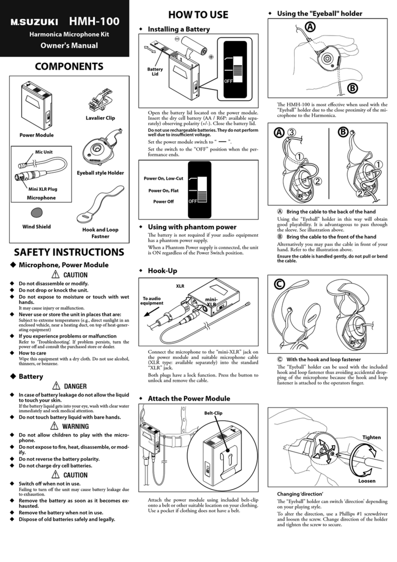
Suzuki Musical Instrument Corp.
Suzuki Musical Instrument Corp. HMH-100 owner's manual
Razer
Razer SEIREN V2 X user manual
Shure
Shure Microflex MX400SE Series user manual
Sennheiser
Sennheiser MZB 415 Instructions for use
Neumann.Berlin
Neumann.Berlin U89i operating manual
