manuals.online logo
Brands
  1. Home
  2. •
  3. Brands
  4. •
  5. BOX15
  6. •
  7. Indoor Furnishing
  8. •
  9. BOX15 T-ABLE 411/78.1900.22 User manual

BOX15 T-ABLE 411/78.1900.22 User manual

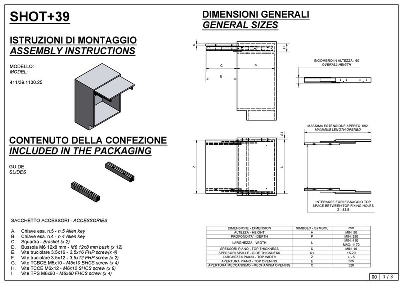
T-ABLE - ISTRUZIONI DI MONTAGGIO
ASSEMBLY INSTRUCTIONS
MODELLI
MODELS
411/78.1900.22 - T-ABLE per modulo da 600 mm spalle da 15 a 20 mm
for 600 mm module, sides thickness: 15-20 mm
411/78.1910.22 - T- ABLE per modulo da 900 mm spalle da 15 a 20 mm
for 900 mm module, sides thickness: 15-20 mm
411/78.1920.22 - T- ABLE per modulo da 1200 mm spalle da 15 a 20 mm
for 1200 mm module, sides thickness: 15-20 mm
1/7
CONTENUTO DELLA CONFEZIONE
INCLUDED IN THE PACKAGING
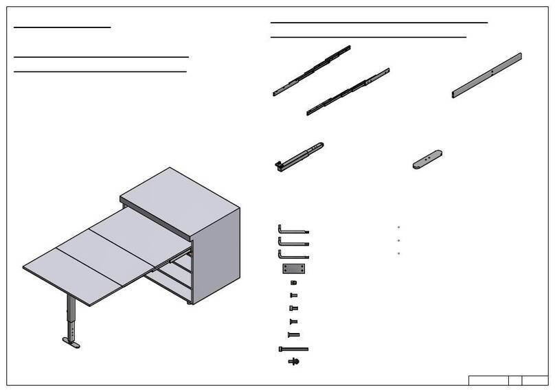
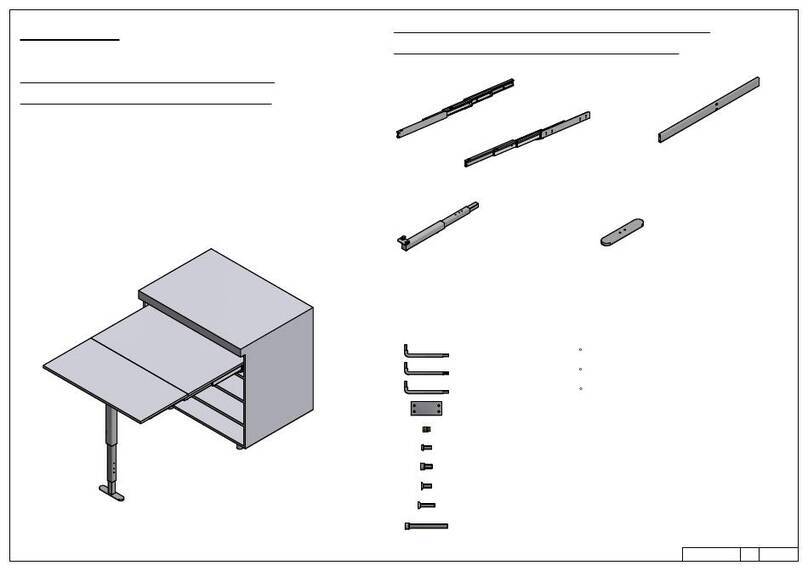
GUIDE PREASSEMBLATE
PRE-ASSEMBLED SLIDES
TRAVERSINO mm 426/726/1026
LA MISURA DIPENDE DAL MODELLO
HORIZONTAL BARS mm 426/726/1026
LENGTH DEPENDS ON MODEL
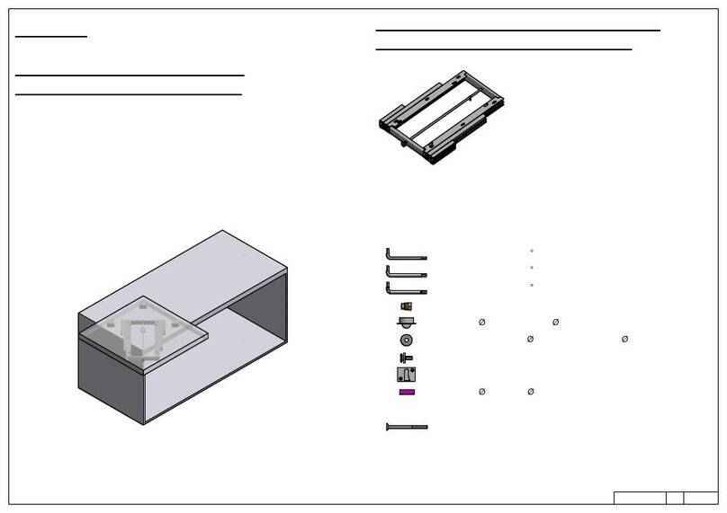
GAMBA PRE-ASSEMBLATA
PRE-ASSEMBLED LEG
PIEDINO
FOOT
ACCESSORI
ACCESSORIES
- A1 - Chiave a brugola da 3 - n°3 Allen key
- A2 - Chiave a brugola da 4 - n°4 Allen key
- A3 - Chiave a brugola da 5 - n°5 Allen key
- B - Vite TCCE M6x12 - M6x12 socked head cap screw ( x 12)
- C - Bussola in ottone M6 - Brass bush M6 ( x 12 )
- D - Vite TCBCE M5x10
M5x10 rounded socked head cap screw ( x8 )
- E - Distanziale
spacer ( x20 )
- F - Vite TCCE M6x60 - M6x60 socked head cap screw ( x 4)
- G - Vite trilobata M6x25 - M6x25 self threading screw ( x 2 )
- H- Vite TPS M6x16 - M6x16 screw ( x 2 )
DIMENSIONI DI MASSSIMA
GENERAL DIMENSIONS
2/7
870570 / / 1170
860560 / / 1160
LARGHEZZA MIN.
MIN. WIDTH
LARGHEZZA MAX.
MAX. WIDTH
PROFONDITA' MIN. NECESSARIA
MIN. NECESSARY DEPTH
ALTEZZADATERRA
HEIGTHFROMFLOOR
60
ALTEZZA
HEIGTH
DIMENSIONE PIANETTI
PLANES DIMENSION
XTOT=840/810/770+0/-25
540
420 529
779
X17
XTOTALTEZZAGUIDE
SLIDEHEIGTH
X TOT = X + 17 = 840/810/770
SONO POSSIBILI TRE POSIZIONI CON
VARIAZIONE DI 25 mm PER OGNI POSIZIONE
THERE ARE THREE POSSIBLE POSITIONS
WITH 25 mm OF REGULATION FOR EACH POSITION
POSIZIONE FORI FISSAGGIO MECANISMO
HOLES FOR MECHANISM POSITION
3/7
RICAVARE SU CIASCUNA SPALLA DEL MOBILE 4 FORI DIAM. 8x13
PER LE BUSSOLE M6 INCLUSE NELLA CONFEZIONE
LA QUOTA INDICATA DI 50 mm, LASCIA UNO SPAZIO LIBERO
TRA GUIDA E PIANETTO SOTTOSTANTE DI CIRCA 25 mm
DRILL ON EACH CABINET SIDE FOUR DIAM. 8x13 HOLES FOR
THE INCLUDED M6 BRASS BUSHES.
THE INDICATED 50 mm DIMENSION LEAVES A FREE SPACE
BETWEN THE BOTTOM OF THE SLIDES
AND THE PLANE OF ABOUT 25 mm
- C Bussola in ottone M6 mm 12x8 (x 8)
M6 mm 12x8 Brass bushes
SPALLA DA 20 mm - NESSUN DISTANZIALE
SPALLA DA 19 mm - 1 DISTANZIALE
SPALLA DA 18 mm - 2 DISTANZIALE
SPALLA DA 17 mm - 3 DISTANZIALE
SPALLA DA 16 mm - 4 DISTANZIALE
SPALLA DA 15 mm - 5 DISTANZIALE
SIDE THICKNESS 20 mm - NO SPACER
SIDE THICKNESS 19 mm - 1 SPACER
SIDE THICKNESS 18 mm - 2 SPACERS
SIDE THICKNESS 17 mm - 3 SPACERS
SIDE THICKNESS 16 mm - 4 SPACERS
SIDE THICKNESS 15 mm - 5 SPACERS
- A2 - Chiave a brugola da 4 - n°4 Allen key
- E - Distanziale - spacer ( x20 )
A: POSIZIONE FORI DIAM. 8x13
PER BUSSOLE M8
POSITION OF DIAM. 8 x 13 HOLES
FOR M6 BUSHES
B: POSIZIONE SCARICHI DA DIAM. 10x5
PER TESTA VITI FISSAGGIO DISTANZIALI (SE USATE)
POSITION OF DIAM. 10 x 5 HOLES
FOR THE HEADS OD SCREWS FIXING THE SPCERS (IF USED)
- D - Vite TCBCE M5x10
- M5x10 rounded socked head cap screw ( x8 )
PER SPALLE DI SPESSORE < 20 mm
USARE I DISTANZIALI IN FERRO A CORREDO
FISSANDOLI SULLE GUIDE ESTERNE.
FOR CABINET SIDES <20 mm
USE INCLUDED STEEL SPACERS
FIXING THEM ON THE EXTERNAL
SLIDES
B
BB
B
A
A
A
A
50,5 64
434,5 64
5016
17
X
Per montare il meccanismo bisogna prima
sfilare le due guide più esterne. Per farlo
svitare la vite posta alla fine delle seconde
guide, e svitare la vite posta sotto la estremità
delle guide esterne. Fatto questo è possibile
sfilare da dietro le guide esterne.
A questo punto le guide esterne si fissano alla
spalla del mobile utilizzando le incluse viti
TCCE M6x12 (B).
Per completare l'operazione, infilare ora il
meccanismo sulle guide esterne e riavvitare le
viti prima svitate.
To mount the mechanism on the cabinet, it is
necessary first to disassemble the two
external slides. To do this, unsrews the two
screws in the rear of the second element and
the screw under
the terminal part of the external slides. Now
fix the esternal slides to the cabinet sides
using the included M6x12 (B) screws. Last,
insert agin the mechanism on the external
slides and thigthen the screws precedentely
unscrewed.
MONTAGGIO DEL MECCANISMO SUL MOBILE
MOUNTING OF THE MECHANISM ON THE CABINET
- B - Vite TCCE M6x12 (x 8)
Socked head cap screw M6x12 (x 8)
- A3 - Chiave esagonale da 5
n°5 Allen key
4/7
GUIDA ESTERNA
EXTERNAL SLIDE
SECONDA GUIDA
SECOND SLIDE SVITARE
UNSCREW
SVITARE
UNSCREW
B
B
B
B
5/7
DIMENSIONI PIANETTI
PLANES DIMENSIONS
IL PIANO FISSO PUO' ESSERE MONTATO UTILIZZANDO
LE QUATTRO VITI TCCE M6x60 (F) FORNITE A
CORREDO INSERENDOLE NEI FORI SULLE GUIDECENTRALI
THE FIXED PLAN CAN BE MOUNTED USING THE
SUPPLIED FOUR SOCKED HEAD SCREWS M6x60 (F)
INSERTED IN PROPER HOLES ON THE CENTRAL SLIDES
- F - Vite TCCE M6x60 (x 4)
Socked head cap screw M6x60
- A3 - Chiave esa. da 5
n°5 Allen key (x 1)
VISTA DAL BASSO
BOTTOM VIEW PIANO FISSO
FIXED PLANE
PIANO FISSO
FIXED PLANE
PIANO RIBALTABILE
TILTING PLANE
PIANO RIBALTABILE
TILTING PLANE
- C Bussola in ottone M6 mm 12x8 (x 8)
M6 mm 12x8 Brass bushes
REALIZZARE SOTTO IL PIANO FISSO n. 4 FORI DIAM. 8x13
PER LE BUSSOLE M6 ( C)
DRILL UNDER THE FIXED PLANE n. 4 DIAM. 8 x 13 HOLES FOR
M6 BRASS BUSHES (C)
556/856/1156
556/856/1156
478/778/1078
29 280
- C -
- F -
420
529
MONTAGGIO TRAVERSINO E GAMBA
LEG ASSEMBLY
- B - Vite TCCE M6x12 - M6x12 socked head cap screw ( x 12)
- A3 - Chiave a brugola da 5 - n°5 Allen key
- A2 - Chiave a brugola da 4 - n°4 Allen key
- H- Vite TPS M6x16 - M6x16 screw ( x 2 )
B
B
B
B
G
G
H
H
- G - Vite trilobata M6x25
M6x25 self threading screw ( x 2 )
6/7
REGOLAZIONE ALTEZZA GAMBA
LEG HEIGTH REGULATION
T-ABLE VIENE FORNITO
CON LA POSSIBILITA' DI MONTARE
LA PARTE TERMINALE DELLA GAMBA
IN 3 DIVERSE POSIZIONI PER AVERE TRE
DIVERSE LUNGHEZZE DELLA GAMBA.
PER SPOSTARE TALE PARTE TERMINALE,
AGIRE SUI DUE GRANI DI FISSAGGIO INSERITI
NEI FORI (A) CON LA CHIAVE A BRUGOLA DA 3
AVVITARE I GRANI PER MUOVERE LA GAMBA
E SVITARLI, UNA VOLTA IN POSIZIONE, PER
FISSARLA IN CORRISPONDENZA DELLA POSIZIONE
SCELTA
T-ABLE COMES WITH THE POSSIBILITY
TO RGULATE THE HEIGTH OF THE LEG
BY MOUNTING THE LOWER PART OF IT IN
THREE DIFFERENT POSITION.
THIS CAN BE DONE USING THE TWO GRAINS
INSERTED IN THE (A) HOLES
WITH THE INCLUDED #3 ALLEN KEY
TO MOVE THE LEG SCREW THE GRAINS, THEN
UNSCREW THEM WHEN IN THE CHOOSEN POSITION.
A
DOPO AVER FISSATO LA PARTE TERMINALEDELLA
GAMBA, E' POSSIBILE UNA ULTERIORE
REGOLAZIONE DI CIRCA 25 mm AGENDO CON
LA CHIAVE A BRUGOLA DA 4 INSERITA NEL
FORO (B) CORRISPONDENTE ALLA POSIZIONE
SCELTA PER LA GAMBA
AFTER FIXING THE TERMINAL PART OF THE LEGS,
IT IS POSSIBLE TO FURTHER ADJUST THE LEG'S
HEIGTH USING THE #4 ALLEN KEY INSERTED INTHE
PROPER (B) HOLES IN THE REAR OF THE LEG.
B
7/7
TIRARE IL POMELLO
PER RUOTARE LA GAMBA
PULL THE KNOB
TO ROTATE THE LEG IL BLOCCO DELLA GAMBA TELESCOPICA
SI AZIONA AUTOMATICAMENTE IN APERTURA
PER SBLOCCARLO PREMERE IL PULSANTE
THE TELESCOPIC LEG BLOCK IS
APPLIED AUTOMATICALLY. TO UNLOCK IT
PUSH THE BUTTON
PER RICHIUDERE LE GUIDE,
SPINGERE LE DUE LEVE ROSSE
TO CLOSE THE SLIDES,
PUSH THE TWO RED LEVERS
SEQUENZA DI FUNZIONAMENTO
FUNCTIONING STEPS

This manual suits for next models

2

Other BOX15 Indoor Furnishing manuals

BOX15 411/78.1245.22 User manual

BOX15

BOX15 411/78.1245.22 User manual
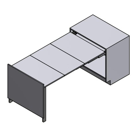
BOX15 EVOLUTION XL 600 411/78.1620.25 User manual
BOX15

BOX15 EVOLUTION XL 600 411/78.1620.25 User manual

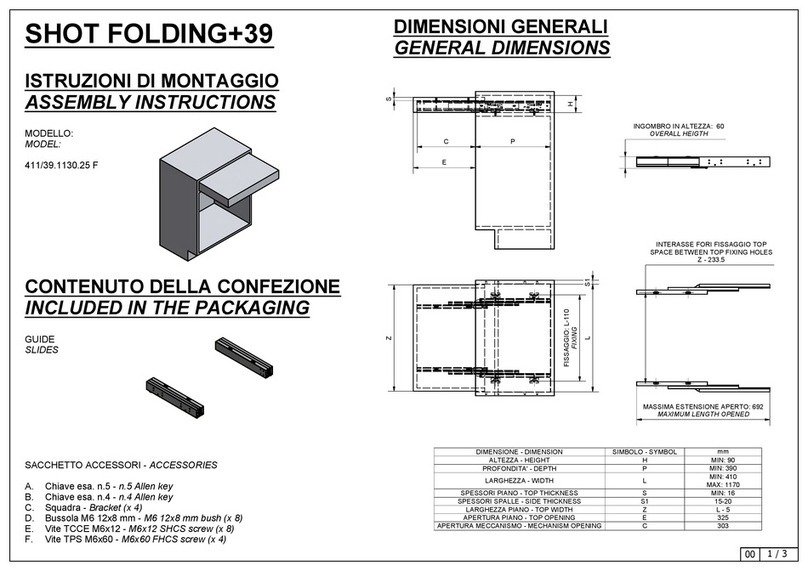
BOX15 411/39.1130.25 F User manual

BOX15

BOX15 411/39.1130.25 F User manual
BOX15 OPLA' FOLDING +39 User manual

BOX15

BOX15 OPLA' FOLDING +39 User manual
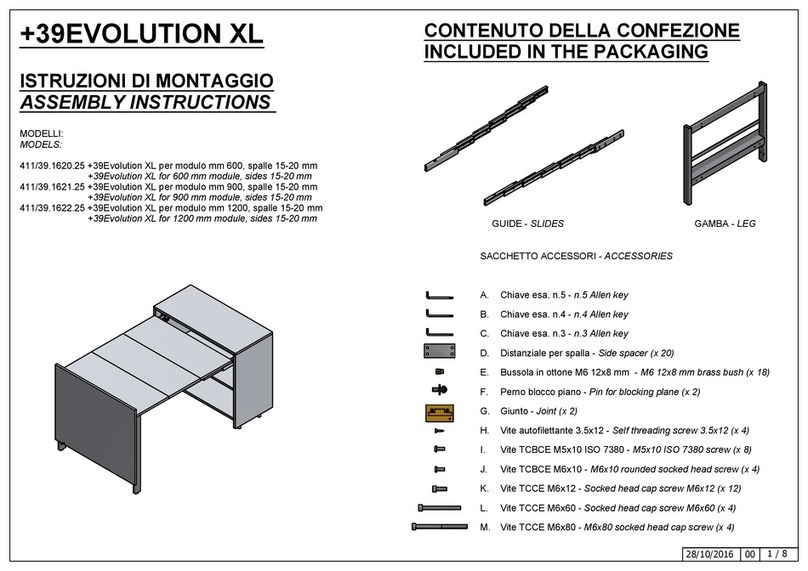
BOX15 +39EVOLUTION XL User manual

BOX15

BOX15 +39EVOLUTION XL User manual
BOX15 EVOLUTION 411/78.1610.25 User manual
BOX15

BOX15 EVOLUTION 411/78.1610.25 User manual

BOX15 LUNCH REVERSE 411/78.1100.25 R User manual

BOX15

BOX15 LUNCH REVERSE 411/78.1100.25 R User manual

BOX15 411/78.1950.22 User manual

BOX15

BOX15 411/78.1950.22 User manual

BOX15 PARTY 411/78.1500.22 User manual
BOX15

BOX15 PARTY 411/78.1500.22 User manual

BOX15 T-BENCH +39 User manual

BOX15

BOX15 T-BENCH +39 User manual

BOX15 BREAKFAST User guide

BOX15

BOX15 BREAKFAST User guide

BOX15 T-ABLE XL User manual

BOX15

BOX15 T-ABLE XL User manual

BOX15 SHOT+39 User manual

BOX15

BOX15 SHOT+39 User manual

BOX15 HOMEWORK User manual

BOX15

BOX15 HOMEWORK User manual

BOX15 T-ABLE User manual

BOX15

BOX15 T-ABLE User manual

Popular Indoor Furnishing manuals by other brands

Regency LWMS3015 Assembly instructions

Regency

Regency LWMS3015 Assembly instructions

Furniture of America CM7751C Assembly instructions

Furniture of America

Furniture of America CM7751C Assembly instructions

Safavieh Furniture Estella CNS5731 manual

Safavieh Furniture

Safavieh Furniture Estella CNS5731 manual

PLACES OF STYLE Ovalfuss Assembly instruction

PLACES OF STYLE

PLACES OF STYLE Ovalfuss Assembly instruction

Trasman 1138 Bo1 Assembly manual

Trasman

Trasman 1138 Bo1 Assembly manual

Costway JV10856 manual

Costway

Costway JV10856 manual

moss DESIGN Caisson Credenza Assembly instructions

moss DESIGN

moss DESIGN Caisson Credenza Assembly instructions

Aquaglide FULL DECK 15.0 owner's manual

Aquaglide

Aquaglide FULL DECK 15.0 owner's manual

AREBOS AR-HE-SW30 user manual

AREBOS

AREBOS AR-HE-SW30 user manual

Till-Hilft Fulda 87005.330 Assembly instructions

Till-Hilft

Till-Hilft Fulda 87005.330 Assembly instructions

Twoey Outside 2010 quick start guide

Twoey Outside

Twoey Outside 2010 quick start guide

Hettich Easys 200 operating instructions

Hettich

Hettich Easys 200 operating instructions

The bedboss RELAX 404 Series owner's manual

The bedboss

The bedboss RELAX 404 Series owner's manual

Oeseder Möbelindustrie Bern 991 720 Assembly instructions

Oeseder Möbelindustrie

Oeseder Möbelindustrie Bern 991 720 Assembly instructions

Costway HW68469 user manual

Costway

Costway HW68469 user manual

Next ALIX A27743 Assembly instructions

Next

Next ALIX A27743 Assembly instructions

BROSA Hans Assembly guide

BROSA

BROSA Hans Assembly guide

Prodigg MINIKA PBA015T-FUR installation manual

Prodigg

Prodigg MINIKA PBA015T-FUR installation manual

manuals.online logo
manuals.online logoBrands
  • About & Mission
  • Contact us
  • Privacy Policy
  • Terms and Conditions

Copyright 2025 Manuals.Online. All Rights Reserved.