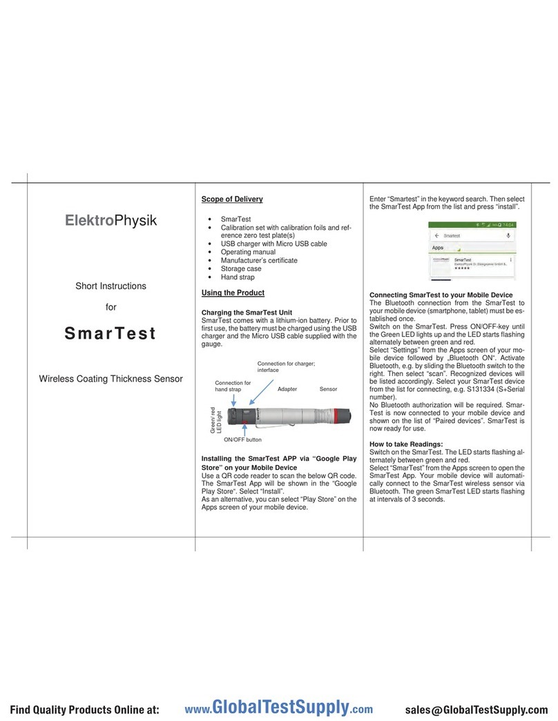
BPC instruments uFlow User manual

µFlow
Gas flow meter
Operation and Maintenance Manual


µFlow

Release History
Version 2.0, February 2022
Any questions related to this Operation and Maintenance manual should be directed to:
BPC Instruments AB
Scheelevägen 22
SE-223 63 Lund
Sweden
Tel: +46 (0)46 163950
Fax: +46 (0)46 163959
Web: www.bpcinstruments.com
This document contains proprietary information that is protected by copyright.
All rights are reserved. No part of this publication may be reproduced in any form whatsoever or translated into any
language without the prior, written permission of BPC Instruments AB.
Copyright © 2022 BPC Instruments AB
Produced in Sweden

TABLE OF CONTENTS
1PREFACE............................................................................................................................... 1
2GENERAL INFORMATION...............................................................................................2
2.1 Conventional Gas Flow Meters........................................................................................2
2.2 Advantages of µFlow over Conventional Flow Meters ................................................... 2
3DELIVERY CHECKS...........................................................................................................4
3.1 Flow Gas Meter Box Content ........................................................................................4
3.2 Optional Equipment .........................................................................................................4
4PRE-COMMISSIONING......................................................................................................7
5QUALITY RULES AND RECOMMENDATIONS...........................................................7
6SAFETY CONSIDERATIONS ............................................................................................ 8
7EQUIPMENT DESCRIPTION (DESIGN/FUNCTION)................................................... 9
7.1 µFlow Gas Meter with Front Power and Analogue Output Port ..................................10
7.2 µFlow Gas Meter with Side Power and Analogue Output Port ...................................11
7.3 Charger for the µFlow Gas Flow Meter.........................................................................12
7.4 Flow Gas Flow Meter Technical Characteristics......................................................... 13
7.5 Data Logger System Technical Characteristics.............................................................. 14
8OPERATION .......................................................................................................................15
8.1 Before Start up................................................................................................................ 15
8.2 Start up ........................................................................................................................... 18
8.3 Monitoring......................................................................................................................18
8.4 End of Operation ............................................................................................................19
9MAINTENANCE.................................................................................................................19
10 µFLOW SOFTWARE.........................................................................................................20
10.1 Installation of the Flow Data Logger Software (Windows 8)......................................20
10.2 Flow Data Logger Software User Guide...................................................................... 34

1
1PREFACE
BPC Instruments AB (BPC) is a privately held company and market leader in the area of
advanced control technologies for the commercial biogas industry, providing technologies and
services that support the efficient design and operation of biogas plants & processes. The
company was founded in 2006, bringing to market more than 15 years of industry leading
research in the area of instrumentation, control and automation of anaerobic digestion processes.
At the end of 2009, BPC launched the Automatic Methane Potential Test System I (AMPTS I), a
revolutionary product in the area of on-site lab equipment for methane potential analysis. The
number of users of AMPTS I grew quickly and today there are users in more than 40 countries,
located in the Americas, EMEA, and Asia Pacific regions. In April 2011 an updated version of
the AMPTS was made commercially available and at the end of 2012 the BioReactor Simulator
(BRS) was introduced to the market. As of January 2013, a new instrument (µFlow) for
measuring ultra-low gas flows with high precision has been offered to the market.
The µFlow is a flow meter which has been designed for on-line, real-time monitoring of gases
over a wide detection range and for most indoor laboratory scale applications. Suitable
applications include biogas process studies, ethanol fermentation, dark fermentation for bio-
hydrogen, and leak rate detection.

2
2GENERAL INFORMATION
Anaerobic biodegradation processes are gaining in interest among industry and local
governments, due to their ability to produce energy and reduce sludge yields.
In the anaerobic biodegradation process, gas flow rate represents a key parameter for evaluating
the performance of a process. In laboratory scale experiments, the bioreactor volume ranges from
1 to 50 l with a low gas production, especially during the start-up period, often within several
hundreds millilitres per hour. Measuring such a low volume of gas accurately is not an easy task
using commercially available gas flow meters since they do not measure such low flow rates.
A gas flow meter for laboratory-scale reactors has higher demands compared with a meter
adapted for a large-scale anaerobic reactor. This includes no gas losses, stable calibration
through time, and higher sampling rates, and ultimately more reliable gas measurements. The
µFlow meets all the needs of the most demanding biogas/biofuel labs and user applications.
2.1 Conventional Gas Flow Meters
Conventional gas flow meters (i) utilise techniques (e.g., thermal, Coriolis mass, ultrasonic,
turbine, vortex shedding etc.) that measure parameters such as velocity or mass of the flowing
stream to indirectly determine the volumetric flow or (ii) measure the volume of the gas directly
by liquid displacement. Although use of the liquid displacement technique is simple and
straightforward, errors associated with volume determination still exist when the investigated gas
is soluble in the displaceable liquid and the barrier solution is in direct and continuous contact
with the atmosphere. Moreover, in order to compare the data obtained from different
laboratories, correction factors need to be included in volume calculations to obtain gas volumes
at standard temperature and pressure, thus reducing or eliminating the error from this source.
2.2 Advantages of µFlow over Conventional Flow Meters
The µFlow provides several unique functionalities that are important for monitoring the gas flow
rate during a biodegradation process:
•Large linear detection range (20 to 4000 ml/h) that fits perfectly with most lab- and small
pilot-scale applications
•Real-time pressure and temperature compensation for gas flow rate and volume
measurements ensure that all gas flow measurements are accurate
•Real-time gas flow rate and normalisation allow for gas measurements to be standardised

3
•Standard analogue current signal output for automatic data acquisition (4-20 mA)
•Low maintenance requirements
•LCD display for visualisation of variables
•The design and calibration delivers highly precise measurements
•One of the most cost competitive solutions on the market today.

4
3DELIVERY CHECKS
At delivery, unpack and check that the contents match with what is listed below in the Section
“Box Content”.
If the packaging or the equipment is broken or damaged at delivery, please:
a) Document and take photos of the parts and packaging.
b) Inform the transport company at the time of delivery.
c) Make sure that the transport company documents the incident.
d) Inform the seller of the incident.
3.1 Flow Gas Meter Box Content
See also Chapter 7 (Equipment Description) for pictures of included parts.
1 flow meter
1 power adapter (input 100-240 V 50/60 Hz, output 12 V DC / 0.5 A)
1 manual
3.2 Optional Equipment
For automatic data logging of gas flow rate, BPC provides two different Data Logger systems
together with the software for Microsoft Windows:
(1) Data Logger with USB interface

5
(2) Universal Data Logger with Ethernet interface
The hardware module includes eight analog current input channels for high-performance control
and monitoring applications. The system features analogue current input ranges of 4 to 20 mA.
To protect against signal transients, the module includes a channel-to-earth ground double
isolation barrier for safety and noise immunity.
When deciding between a USB and Ethernet interface, it’s important to weight the advantages
and disadvantages of both.
When it comes to the Data Logger unit with a USB interface, the most obvious benefit is cost. In
addition, the USB instrument is easier to install and most PCs have plenty of USB ports to
choose from. On the downside, the Data Logger with USB interface can only be accessed over a
relatively short distance. In addition, the USB connection is not really designed for reliable data
communication over a long period of time.
While slightly more expensive, the Universal Data Logger unit with Ethernet interface offers
more functionality by allowing the user to set each channel to measure not only gas flow, but
also temperature, pH and methane content. It also has a greater flexibility with regards to
distance (cable length up to 100 m) between Data Logger and computer, as well as a more stable
connection. (For more information about the Universal Data Logger, please read the Universal
Data Logger Operation and Maintenance Manual.)
In short, if the aim of the µFlow user is to view real-time data, in the immediate vicinity of the
device under test and store the data on the local hard driver, a Data Logger unit with USB
interface is the economical choice. If, on the other hand, the user is interested in a product with
more functionality, flexibility and reliability of data communication over a long period of time,
the Universal Data Logger unit with an Ethernet interface is the best choice.
The Data Logger software automatically logs the gas flow rate, shows a real-time visualisation of
the flow rate trend curve, as well as provides report generation. One Data Logger system can

6
support up to 8 µFlow devices. A Data Logger unit is not included in the standard µFlow
package. A screenshot of the software user interface is presented below.

7
4PRE-COMMISSIONING
The following items are not included in the delivered µFlow, however they will/may be required
to operate the flow meter:
•Data acquisition system available from BPC
•Additional wall socket adapters (plugs/contacts), as the ones supplied are according to
European, US or UK standards, depending on original purchase order
•If the customer has a gas chromatograph and is interested in off-line biogas composition
analysis, gas-sampling units can be ordered separately from BPC.
5QUALITY RULES AND RECOMMENDATIONS
•The product guarantee provided corresponds to the guarantee stipulated on the confirmed
product order form and shipping documentation
•For high accuracy measurements, the µFlow should not be exposed to mechanical
vibrations and/or high frequency radio transmissions and should be placed on a level and
stable surface
•Only the parts delivered with the product can be used with the system in order to
guarantee the quality and performance of the product
•BPC reserves the right to correct any possible text and image errors as well as changes to
technical data in this manual.
Before Getting Started
•Read this manual before installing and using the equipment.
•Keep the instruction manual for future reference and make sure it is easily available for
people who regularly use the µFlow.
•If the Universal Data Logger is used with the µFlow Gas Meter, please read the Universal
Data Logger Operation and Maintenance Manual.

8
6SAFETY CONSIDERATIONS
The µFlow should be used in an environment with good ventilation, preferably in a laboratory
fume hood, especially when this detection unit is connected to bioreactors, which are generating
very high volumes of toxic or slightly aggressive gases.
Always be cautious when handling electrical devices close to water.

9
7EQUIPMENT DESCRIPTION (DESIGN/FUNCTION)
The µFlow is a flow meter for ultra-low gas flow detection. Its design and highly precise
calibration delivers a measurement precision of ± 1%, with a resolution of about 10 ml.
Therefore, the µFlow meets the needs of the most demanding biogas/biofuel labs and user
applications.
The unit contains a glass window, allowing for visual inspection of the flow cell movement, and
has an adjustable foot to ensure the correct installation position for high precision measurements.
The measuring device works according to the principle of liquid displacement and buoyancy; a
digital pulse is generated when a defined volume of gas flows through the device. The unit offers
a standard signal output for automatic data acquisition and provides users with an embedded
timer and reset button for easy logging of accumulated gas flow volume over a defined period of
time.
The µFlow automatically normalises gas flow and volume measurements with real-time
temperature and pressure compensation. This allows for gas measurements and data presentation
to be standardised and thus, the impact of measurement conditions are minimised. The
temperature and pressure of the gas are measured every time a flow cell opens, allowing the user
to derive exact kinetic information compensated for any variation over time. The volumes are
normalised to 0 C and 1 atm.
There are two versions of the µFlow Gas Meter available. One has the power supply and
analogue output connectors on the front (7.1), and the other has a combined port for power
supply and analogue output on the side (7.2).

10
7.1 µFlow Gas Meter with Front Power and Analogue Output Port
(1) Outlet for gas flow
(7) Glass window for visual inspection of the
flow cell movement
(2) Level gauge
(8) Liquid Crystal Display (LCD) for real time
visualisation of normalised gas volume & flow
rate, duration of the experiment and version of
the software
(3) Port for filling water
(9) Adjustable foot
(4) Inlet for gas flow
(10) Button for instant pressure and
temperature display (press for less than 5
seconds) and for resetting the timer (press for
more than 5 seconds)
(5) Maximum filling level indicator
(11a) Power input
(6) Minimum filling level indicator
(11b) Standard signal output for automatic
data acquisition

11
7.2 µFlow Gas Meter with Side Power and Analogue Output Port
(1) Outlet for gas flow
(7) Glass window for visual inspection of the
flow cell movement
(2) Level gauge
(8) Liquid Crystal Display (LCD) for real time
visualisation of normalised gas volume & flow
rate, duration of the experiment and version of
the software
(3) Port for filling water
(9) Adjustable foot
(4) Inlet for gas flow
(10) Button for instant pressure and temperature
display (press for less than 5 seconds) and for
resetting the timer (press for more than 5
seconds)
(5) Maximum filling level indicator
(11) Combined power input and analogue output
port
(6) Minimum filling level indicator

12
Angle view of the µFlow meter with the combined power input and analogue output port on the
side:
7.3 Charger for the µFlow Gas Flow Meter
The power input port is located at different positions on the two versions of the µFlow meters.
The charger is inserted at (11b) on the front of the µFlow meter described in chapter 7.1, and at
(11) on the side on the µFlow meter described in chapter 7.2.

13
7.4 Flow Gas Flow Meter Technical Characteristics
GENERAL
Measuring resolution: 10 ml
Measuring range: 20 to 4000 ml/h
Signal output for flow rate: 4-20 mA
Repeatability: 1%
Working principle: liquid displacement & buoyancy
Built-in sensors: pressure and temperature
LCD display: normalised gas flow (NmL/h), volume (Nml) and time (min)
Materials: high quality aluminium
Dimension: 19×14×6 cm
Weight: 0.180 kg
Power supply: input 100-240 V 50/60 Hz, output 12 V DC / 0.5 A
Usage: indoor applications for inert and slightly aggressive gases
FEATURES
Large linear detection range (up to 4000 ml/h), which fits perfectly with most of lab-
and small pilot-scale applications
Embedded timer and reset button for easy logging of accumulated gas volume over a
defined period of time
Automatic gas flow and volume normalisation with real-time temperature and pressure
compensation, which allow for gas measurement standardisation
Standard analogue current signal output (4-20 mA) for automatic data acquisition
Adjustable foot and horizontal gauge to ensure the correct installation position for high
precision measurements
Glass window for visualisation of flow cell movement
Low maintenance requirements
Pre-calibration to ensure measurement accuracy

14
7.5 Data Logger System Technical Characteristics
The PC-based Data Logger system for µFlow consists of a hardware module controlled by an
easy-to-use software program.
DATA LOGGER HARDWARE
The hardware module has 8 plug & play terminal connectors that provide connections for 8
analog input channels. Each channel has an AI plug & play terminal to which you can
connect a current signal. The module has a common terminal, COM that is internally
connected to the isolated ground reference of the module.
The main characteristics of the hardware module are presented below:
•8 analogue current input channels
•4 to 20 mA programmable input ranges
•Universal Data Logger with Ethernet interface: 16-bit resolution, 200 kS/s
aggregate sampling rate
•Flow Data Logger with USB interface: 12 bit resolution, 10 kS/s sampling rate
•Indoor application only
•Power adapter: input 100-240 V 50/60 Hz, output 24 V DC /0.5 A or higher.
DATA LOGGER SOFTWARE
The Data Logger software is needed in order for the Data Logger hardware to work with a
PC. It is delivered on a USB card together with the Data Logger hardware. Please notice that
the Data Logger software is delivered with a license control and can only work together with
the Data Logger hardware delivered at the same time.

15
8OPERATION
In this section, references are given to pictures in the Chapter 7 (Equipment Description) in the
form of a number within parenthesis, e.g., (1).
8.1 Before Start up
INSTALLATION OF THE µFLOW GAS METER
a) Install the instrument on a flat and stable surface. Use appropriate instrumentation (i.e.,
bubble level device) to verify the horizontality of the surface and to adjust its position if it
is needed.
b) Use the adjustable foot (9) and the level gauge (2) to ensure the correct installation position.
c) Fill up the measurement chamber with the packing liquid (e.g., deionised or distilled water)
through the port specially designed for filling the packing liquid (3) by using a small
syringe. It is also possible to fill the instrument through the gas flow inlet (4) with the help
of a small syringe.
d) Check the water level in the chamber. It should be within the limits of the marking. A water
level below the minimum acceptable level (6) can cause errors in the measurement of the
volume and flow rate of the gas.
e) If the µFlow Gas Meter will be used as a stand-alone unit (i.e. without a Data Logger
system) connect the power cable to the power connector on the front (11a) or to the
combined power and analogue output port on the side (11), depending on what version of
the µFlow Gas Meter is used. Then connect the power adapter to a power outlet.
If the µFlow Gas Meter with the analogue output port on the front is used as a stand-alone
unit, the green terminator plug must be inserted in the analogue output port (11b).
f) If the unit will be connected to a Data Logger system, connect the power cable to either the
power input (11a) and the analogue output cable to the port on the front (11b), or to the
combined power and analogue output port on the side (11), again depending on which
version is used.
When a Data Logger System is used, make sure that the end of the analogue output cable
marked with blue (or grey for same versions) is always connected to the Data Logger, and
not to the µFlow Gas Meter.
Table of contents
Other BPC instruments Measuring Instrument manuals
