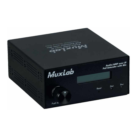
B+B Sensors 0555 0035-01 User manual

Operating Manual
TxRail-USB Temperature Transmitter
0555 0035-01 – 4-20 mA 0555 0035-02 – 0-10 V
B+B Thermo-Technik GmbH
Heinrich-Hertz-Str. 4 | D-78166 Donaueschingen

TxRail-USB Temperature Transmitter
0555 0035-01, 0555 0035-02
0141 0315-951 27.09.2021
B+B Thermo-Technik GmbH | Heinrich-Hertz-Str. 4 | D-78166 Donaueschingen
Seite 1von 9
Technische Änderungen vorbehalten
Fon +49 771 83160 | Fax +49 771 831650 | info@bb-sensors.com | bb-sensors.com
Contents
...................................................................................................................................................................................................................................0
1Foreword...........................................................................................................................................................................................................1
2General Advice .................................................................................................................................................................................................1
Labels..........................................................................................................................................................................................................1
Warning Advice...........................................................................................................................................................................................1
Security Advices..........................................................................................................................................................................................2
3Introduction .......................................................................................................................................................................................................3
4Technical Specifications ...................................................................................................................................................................................3
5Mechanical Installation......................................................................................................................................................................................4
Öffnen des Messumformers........................................................................................................................................................................4
6Elektrical Installation .........................................................................................................................................................................................4
Recommendations for Installation...............................................................................................................................................................5
Electrical Connections.................................................................................................................................................................................5
6.2.1 Pt100 2-wires / NTC ..........................................................................................................................................................................5
6.2.2 Pt100 3-wires.....................................................................................................................................................................................5
6.2.3 Pt100 4-wires.....................................................................................................................................................................................5
6.2.4 Thermoecouples and 0 – 50 mV .......................................................................................................................................................5
6.2.5 Output................................................................................................................................................................................................6
7Configuration.....................................................................................................................................................................................................6
Software Configuration................................................................................................................................................................................7
Factory Settings ..........................................................................................................................................................................................7
8Operation ..........................................................................................................................................................................................................7
9Questions?........................................................................................................................................................................................................8

TxRail-USB Temperature Transmitter
0555 0035-01, 0555 0035-02
0141 0315-951 27.09.2021
B+B Thermo-Technik GmbH | Heinrich-Hertz-Str. 4 | D-78166 Donaueschingen
Seite 1von 9
Technische Änderungen vorbehalten
Fon +49 771 83160 | Fax +49 771 831650 | info@bb-sensors.com | bb-sensors.com
1FOREWORD
Dear customer,
We thank you for having purchased the TxRail-USB Temperature Transmitter and are very glad that you decided in favour of a product of B+B
Thermo-Technik GmbH. We hope this product will fully satisfy you and will assist you effectively in your work.
This Device has been developed to be technically highly up-to date. This product has been designed in accordance with the regnant European
and German national directives and rules. For a proper and effective usage of the product the customer shall observe the following Operating
Instructions. In the case that against one’s expectations any troubles occur which you cannot resolve yourself, please contact our service
centers or your salesperson. We go after giving you rapid and competent help to minimize the risk of long-time outfalls.
The following operating Instruction is an indispensable part of this Product. It contains important advices for the starting up and further
use of the device
2GENERAL ADVICE
This documentation contains information which must be paid in attention to assure a highly effective and secure use of the supplied product
Please read through the following instructions and make yourself familiar with the handling of the product before you insert it in your processes.
Keep this document always readily to hand so you can consult it by need.
Labels
Symbol
Meaning
Descripton
Advice
It is necessary to read the following advice before beginning the operations. The
used symbols in the manual acts first as eye catcher for security risks. The
symbols do not replace the security advice. The text must be read to the end
Necessary to observe This symbol designates important advice and tips that are necessary for the
success a work step. They must be followed to get good results
Warning Advice
Symbol
Meaning
Symbol
Meaning
This symbol advises the user of danger for persons,
material, or environment. The text gives information that
must be necessarily followed to avoid any risks
Caution against electromagnetic fields (BGV A8, GUV-V
A8/W12)
Caution against hot surfaces (BGV A8, GUV-V
A8/W26) and hot liquids or substances
Caution against severe cold
(BGV A8, GUV-V A8/W17)
Caution against liquids and hot substances Caution against dangerous high electrical voltage
(BGV A8, GUV-V A8/W08)
Caution against dangerous ex-plosive substances
(BGV A8, GUV-V A8/W02)
Caution against dangerous explosive atmosphere
(BGV A8, GUV-V A8/W21)
Caution against mobile engines (W29)
Caution against moving parts
Electronic waste

TxRail-USB Temperature Transmitter
0555 0035-01, 0555 0035-02
0141 0315-951 27.09.2021
B+B Thermo-Technik GmbH | Heinrich-Hertz-Str. 4 | D-78166 Donaueschingen
Seite 2von 9
Technische Änderungen vorbehalten
Fon +49 771 83160 | Fax +49 771 831650 | info@bb-sensors.com | bb-sensors.com
Security Advices
B+B Thermo-Technik GmbH assume no liability for damages occurred through failure to observe these security advices. A usage non conform
to the instructions given in this manual can damage the device
BODY AND PROPERTY DAMAGES
The national and local standards for electrical installations must be se strictly observed.
The use of the device is strictly reserved / restricted to properly schooled / qualified operators.
The system is not adequate for use in atmosphere with explosion danger.
Do not use the system in a high electric or magnetic field area
ENSURING OF PRODUCT SECURITY
The system must be operated only within the limits given in the technical Data
Exposing the system to hot temperatures (higher than the operating temperature) will cause damages in the electronic
circuits and also damage the housing
USAGE ACCORDING TO PURPOSE
Please use the product only for the purposes for which it is conceived. In case of doubt, please first contact B+B Thermo-
Technik GmbH
DISOPOSAL
Please return the device to B+B Thermo-Technik GmbH after expiration of its lifetime
.
.

TxRail-USB Temperature Transmitter
0555 0035-01, 0555 0035-02
0141 0315-951 27.09.2021
B+B Thermo-Technik GmbH | Heinrich-Hertz-Str. 4 | D-78166 Donaueschingen
Seite 3von 9
Technische Änderungen vorbehalten
Fon +49 771 83160 | Fax +49 771 831650 | info@bb-sensors.com | bb-sensors.com
3INTRODUCTION
The TxRail-USB is an USB configurable DIN rail mount temperature transmitter. It allows selection and configuration of input type, measurement
range, output type and calibration. Its output can be set to either loop powered 4-20 mA or 0-10 Vdc. Highly accurate and user-friendly, the
TxRail-USB performs well from simple to sophisticated measurement applications.
The output current or voltage is linearized according to the selected input sensor and adjusted to the configured range.
4TECHNICAL SPECIFICATIONS
Sensor Input
User defined. The supported sensors are listed in Table 1, along with their maximum
ranges.
Maximal Voltage on the Sensor terminals 3 V
Thermocouples
Type J, K, R, S, T, N, E and B, according to DIN EN 60584 (ITS-90). Impedance >> 1 MΩ
Pt100
Excitation 0.8 mA, α= 0.00385, according to DIN EN 60751 (ITS-90).
For 2-wire sensors, terminals 3 and 4 must be short circuited.
Pt1000
Excitation 0.8 mA, α= 0.00385, according to DIN EN 60751 (ITS-90).
For 2-wire sensors, terminals 3 and 4 must be short circuited.
NTC R
25°C
10 kΩ±1 %, B
25/85
= 3435
Voltage
0 … 50 m VDC. Impedance >> 1 MΩ
Sensor type
Maximal
Minimal
Range
Linearisation span
Spannung
0 … 50 mV
5 mV
Thermoelement K
-150 … 1370 °C
100 °C
Thermoelement
J
-100 … 760 °C
100 °C
Thermoelement R
-50 … 1760 °C
400 °C
Thermoelement S
-50 … 1760 °C
400 °C
Thermoelement T
-160 ... 400 °C
100 °C
Thermoelement N
-270 ... 1300 °C
100 °C
Thermoelement E
-90 ... 720 °C
100 °C
Thermoelement B
500 … 1820 °C
400 °C
Pt100
-200 ... 650 °C
40 °C
Pt1000
-200 ... 650 °C
40 °C
NTC
-30 ... 120°C
40 °C
TABELLE 1SUPPORTED SENSORS
Terms of reference
Ambient 25 °C; Voltage: 24 VDC, Load: 250 Ω; Setting time: 10 min
Temperature effects
< ±0,16 % / 25 °C
Switch-on delay
typical 2,5 s . the accuracy is guaranteed only after 15 minutes
Excitation
Pt100, Pt1000, NTC
800 µA
Wiring
Pt100, Pt1000, NTC
Maximal allowable cable resistance 25 Ω
Cable resistance effect 0,005°C / Ω
Accuracy
Sensor
Typical
Max.
Pt100 / Pt1000 (
-150 .. 400°C)
0,10 %
0,12%
Pt100 / Pt1000 (
-200 .. 650°C)
0,13 %
0,19%
mV, K, J, T, E, N, R, S, B
0,1 % (*)
0,15 % (*)
NTC
0,3 °C
0,7 °C
TABELLE 2Sensor accuracy
(*) Add cold junction compensation:< ± 1 °C
Power supply influence
0,006 % / V typical (% of FS ).
Output
4-20 mA
4-20 mA or 20-4 mA, 2-wire, linear, proportional to the configured range

TxRail-USB Temperature Transmitter
0555 0035-01, 0555 0035-02
0141 0315-951 27.09.2021
B+B Thermo-Technik GmbH | Heinrich-Hertz-Str. 4 | D-78166 Donaueschingen
Seite 4von 9
Technische Änderungen vorbehalten
Fon +49 771 83160 | Fax +49 771 831650 | info@bb-sensors.com | bb-sensors.com
0-10 V
0-10 VDC or 10-0 VDC linear, proportional to the configured range
Resolution
4-20 mA
2µA
0-10 V
0,0025 V (12 bits)
Power supply
4-20 mA Output
10 ... 35 VDC
0-10 V Output
12 ... 35 VDC
Maximal Load
RL (max.) = (VDC – 10) / 0,02 [Ω]
where VDC= Power supply (10-35V)
Operating Temp.
-40…85 °C
Humidity
0...90 % RH
EM Compatibility
EN 61326-1:2006
No electrical isolation between input and output.
Internal protection against polarity inversion
Cold junction compensation for thermocouples
Wires
0,14 …1,5 mm²
Screw Tightening
0,8 Nm (empfohlen)
Housing
ABS UL94-HB
Certificates
CE
5MECHANICAL INSTALLATION
The TxRail-USB transmitter is suitable to be installed on 35 mm
DIN rail. Vibrations, moisture and extreme temperatures, electro-
magnetic interference, high voltage and other interferences can
permanently damage the unit, and could cause error in the
measured value Abmessungen
Öffnen des Messumformers
To open the transmitter, you must press the orange lockers
located on both sides of the enclosure and pull the frontal cover very
carefully, just like shown in Fig. 2.
6ELEKTRICAL INSTALLATION
•Housing made of polyamide
•Cable / wires: 0,14 … 1,5 mm ²
A
BBILDUNG
1
Dimensions
ABBILDUNG 2Opening the Transmitter

TxRail-USB Temperature Transmitter
0555 0035-01, 0555 0035-02
0141 0315-951 27.09.2021
B+B Thermo-Technik GmbH | Heinrich-Hertz-Str. 4 | D-78166 Donaueschingen
Seite 5von 9
Technische Änderungen vorbehalten
Fon +49 771 83160 | Fax +49 771 831650 | info@bb-sensors.com | bb-sensors.com
A
BBILDUNG
4
•Recommended torque fort he connection screws: 0.8 Nm
Recommendations for Installation
•Conductors of small electrical signals must be distant from Power supply and high-tension/current conductors, preferably passing
through grounded conduits.
•A specific electrical power supply network should be provided for instruments use only
•In controlling and monitoring applications, possible consequences of any system failure must be considered in advance.
•RC filters (47R an 100nF, serial) in inductor charges (contactors, solenoids, etc.) are recommended
Electrical Connections
The figures below show the electrical connections required. The terminals 1, 2, 3 and 4 are dedicated to the sensor connection. LOAD
represents the 4-20 mA current or 0-10 V voltage measuring device (indicator, controller, recorder, etc.).
6.2.1 Pt100 2-wires / NTC
Note: When the Pt100/Pt1000 2-wire the terminals 1 and 3 must be interconnected,
according to the figure below. To use the Pt100/Pt1000 2-wire, you must configure the
Pt100/Pt1000 3-wire option in TxConfig II. The Pt100/Pt1000 wire length should be less than
30 cm to
maintain the measurement error within specifications (electrical
resistance).
6.2.2 Pt100 3-wires
6.2.3 Pt100 4-wires
Pt100 3 and 4-wire: For appropriate cable resistance compensation they should be equal for all legs. Maximum wire resistance is 25 Ω per
wire leg. Usage of a 3 or 4 wire with conductors of equal length and gauge is recommended.
6.2.4 Thermoecouples and 0 – 50 mV
A
BBILDUNG
3
ABBILDUNG 5
ABBILDUNG 6

TxRail-USB Temperature Transmitter
0555 0035-01, 0555 0035-02
0141 0315-951 27.09.2021
B+B Thermo-Technik GmbH | Heinrich-Hertz-Str. 4 | D-78166 Donaueschingen
Seite 6von 9
Technische Änderungen vorbehalten
Fon +49 771 83160 | Fax +49 771 831650 | info@bb-sensors.com | bb-sensors.com
6.2.5 Output
7CONFIGURATION
Changes to the configuration are possible through the TxConfig II software, provided free of charge. The transmitter configuration interface
(USB cable) can be purchased from the manufacturer or its authorized sales representatives.
The TxConfig II software is continuously updated, and new versions can be downloaded at no charge from the manufacturer’s website. To
install, execute the TxConfigIISetup.exe file and follow the instructions.
During the setup, the transmitter is powered by the USB, not requiring an external power supply. The transmitter setup can also be made by
connecting it to the loop, using the loop power supply. There is no electrical insulation between the transmitter and the communication port
(interface), therefore it is not recommended to configure it with the sensor inlet connected to the process. See Fig. 2
After these connections, the user must run the TxConfig II software and, if necessary, consult the Help topic to help using the software.
The USB communication port (interface) of the TxBlock-USB is not electrically insulated from the transmitter’s
input.
A
BBILDUNG
7
A
BBILDUNG
8
Strom (rechts) - Spannung (links)
ABBILDUNG 9USB cable connection

TxRail-USB Temperature Transmitter
0555 0035-01, 0555 0035-02
0141 0315-951 27.09.2021
B+B Thermo-Technik GmbH | Heinrich-Hertz-Str. 4 | D-78166 Donaueschingen
Seite 7von 9
Technische Änderungen vorbehalten
Fon +49 771 83160 | Fax +49 771 831650 | info@bb-sensors.com | bb-sensors.com
Software Configuration
The fields in the screen mean:
1. General Information: This field shows information that identifying the transmitter. This information should be sent to the manufacturer
in an eventual request for technical assistance.
2. Sensor: Select the type of sensor to be used. See Table 1.
3. Measuring Range: Sets de measurement range of the transmitter.
a. Lower Range Limit: Desired temperature for minimum retransmission value.
b. Upper Range Limit: Desired temperature for maximum retransmission value.
c. Sensor Range The values chosen cannot exceed the range of sensor shown in this field. See Table 1 of this manual.
d. Minimum Range Do not set a lower band (span) that the Minimum Range indicated below in this same field. See Table 1 of
this manual.
4. Sensor Failure: It establishes the output behavior, when the transmitter indicates a failure:
a. Minimum: output current goes to < 3.8 mA or output voltage is 0 V (down-scale), typically used for refrigeration.
b. Maximum: output current goes to > 20.5 mA or output voltage is 10 V (up-scale), typically used for heating.
5. Zero Correction: It corrects small deviations presented in the transmitter output, for example, when the sensor is replaced.
6. Send Configuration: It applies the new setup. Once sent, the setup will be immediately adopted by the transmitter.
7. Read Configuration: Reads the current setup in the transmitter connected. The screen now presents the current setup that may be
changed by the user.
Factory Settings
Sensor: Pt100 3-wire, range 0 to 100 °C
Sensor failure: upscale (maximum).
0 °C zero correction.
Unit: °C;
Output: 4-20 mA.
8OPERATION
The sensor offset can be changed through the TxConfig II software. The USB cable may be connected to the transmitter without causing
A
BBILDUNG
10
Hauptfenster TxConfig II

TxRail-USB Temperature Transmitter
0555 0035-01, 0555 0035-02
0141 0315-951 27.09.2021
B+B Thermo-Technik GmbH | Heinrich-Hertz-Str. 4 | D-78166 Donaueschingen
Seite 8von 9
Technische Änderungen vorbehalten
Fon +49 771 83160 | Fax +49 771 831650 | info@bb-sensors.com | bb-sensors.com
any measurement errors. See item Zero Correction in the chapter CONFIGURATION of this manual.
The user must choose the most suitable sensor and range to the process. The chosen range must not exceed the maximum range of
measurement defined for the sensor and should not be smaller than the minimum range for the same sensor.
It is important to note that the transmitter accuracy is based on the maximum range of the sensor used, even when a narrower
range is programmed. Example:
The Pt100 sensor in the range 0 to 100 °C and accuracy of 0.12 %, the maximum error will be 1.02 °C (0.12 % de 850 °C).
The Pt100 sensor in the range 500 to 600 °C and accuracy of 0.19 %, the maximum error will be 1.61 °C (0.19 % of the 850 °C).
Note: When measurements are made at the transmitter, see if the Pt100 excitation current required by the calibrator is compatible with the
Pt100 excitation current used in the transmitter: 0.8 mA
9QUESTIONS?
For further Information about this or other products of B+B Thermo-Technik GmbH please do not hesitate to contact us at:
B+B Thermo-Technik GmbH
Heinrich-Hertz-Straße 4
78166 Donaueschingen
Deutschland
Tel.: +49 771 83160
Fax: +49 771 831650
E-Mail: info@bb-sensors.com
www.bb-sensors.com
This manual suits for next models
4
Table of contents
Popular Transmitter manuals by other brands
Duon System
Duon System AUTROL Series Operation manual
WIKA
WIKA S-11 operating instructions

Enersound
Enersound T-588 quick start guide
Bircher
Bircher RFGate 3.2.T Supplementary sheet to the original instruction manual
Air Monitor
Air Monitor VELTRON III quick start guide
SVT
SVT SHT-127 D operating instructions
