manuals.online logo
Brands
  1. Home
  2. •
  3. Brands
  4. •
  5. B+K precision
  6. •
  7. Portable Generator
  8. •
  9. B+K precision 4012A User manual

B+K precision 4012A User manual

5 MHz
SWEEP
FUNCTION
GENERATOR
with
DIGITAL
DISPLAY
KKPBEffi"
KKPBEffi"
22820Saviranch
Parkway
-Yorba
Linda,
CA92887
www.bkprecision.com
@
2004
B&K
Precision
CorP.
481-531-9-001 Printed
in
Taiwan
\orrnai use
of test
equrpmenr
exposes
i,ou
io r Jertarn
rrnount
of ilanger
from electncel
shockbecause
iestlng
:nust
'omelimes
ae
pefit',*ed '!ner:
exposed
voltagelspresenr.
An elecncel ;hock:ausrng lt)r-riruiirmps
,i e
urrent
ropassihrough
rhe
hean
will ;top nost human
heerlbeets
\")ltxgeis
low es
35
voltsdcor
rc rrns
shouid
be
consrdered
dangerous
rnd hazardous
since
itcan
prociuce
a
lethal
cunenlunder
ceftaln
conditions
Htuher
voltages
posean
even
greater
threat
because
such
,ioitage
crn more
:rsrly Droduce
r lethal
cunenr.
Your norrnal
.'lork
hrbrts
should
include
-rll
rccepted
prrctic::
ro preven!
contacl
wlth exposed
hrgh
vcltage.
and
ro steer
.u.r"n, .*"0 irom ;-our
hean rncese
of acctcientei
'ontact wrth r hrgh
voitage Y'lu wlil
signrficantiy
reduce
the
nsx iactor
if liou
klow and
ilbser.,'e
the
icllo.ling lafety precauttons:
L Don.t expose
trigh
voltage
needlessly.
Remove
housings
lncl
covers
onil w!:n necessarv.
Turn ')ff equlpment
whtlemaking
test
:jonnectron\
n
TEST
INSTRUMENT
SAFETY
high-vollge circuits.
Drscharge
hlgh-volrage
capacitors
lfter removtnq
power'
2. If possibie,
fam-liranze
yourself
wrth
thecquipment
belng
r:ested
anii
'rhe
iocatron
oi its
high voluge polnts
ntry ,pp.tt at
unexpected
poinm
rndefective
equipment'
l. use an
insuiated
floor mate.al or alarge,
rnsulated
iloor matto stand
\)n.rnd rn insulated
work iurface
on "T
htch
to placeequlpment
certainsuch surlaces
a-re
notdamp or wet'
-1.Use
the
lrmeproven..one
hand
in rhe
pocker"technrque
whrlehandling
an instrument
probe Be partlculeriv
:rrerui to "tvotd
:onracinq
r neuD)
metaiobject rhat
could provtdeegood ground return
path.
5 Whentestingacpoweredequrpment.rememberthateclinevoltageisusuallypresen'ronsomeDowerinputctrcuitssuchastheLln-rltf;wltcn'iuses
power
i*nstormar. .ra.anf trme
theequrpment
isconnected
LoJn ac
L)utiet'
iven if thc
equrpment
isturned
orf
icontinued
on
inside
back
coverl
Instruction
Manual
for
MODEL40124,
5 MHz
SWEEPIFUNCTION
GENERATOR
with
Digital
Display
{ri'"
DT EE'E}"G'41|A'=
T'N '-ITEUE'.IUII
However.
remember
:hat
:rtgh
"ilita-ue
lnd make
22820
Savi
ranchParkway
-Yorba
Linda,CA
92887
TABLE
OF
CONTENTS
TEST
INSTRU}VIENT
SAFETY
TNTRODUCTION
SPECIFIC.\TIONS
CONTROLS
AND INDICATORS
OPERATINC
TNSTRUCTIONS
Frequency
and
WaveformSelectton
Considerations
Dury
Cycle
Control
TTL/CMOS
Ourput
Sweep
Consideranons
page
inside
tiont cover
.3
. ..1
.6
I
3
9
IO
ii
VolugeControlled
Frequency
Operatton
Ourput
Protection
Considerations
Functron
Generator
Appiications
Cuidebook
.\IAINTENANCE
Disassembiy
and
ReassemblY
Fuse
Replacement
Line
VoltageSelection
Instrument
Repair
Servtce
WARR\\TY SERV
ICEINSTRUCTIONS
LIIV1ITED
ONEYEARWARRANTY
Li
L2
I3
L.r
lr+
i4
l5
li
I9
INTRODUCTION
The B+K Precision Model .l012ASweep/Function Cenerator is a
versatrie
signal source which combrnesseveral functions lnto one
unit-waveform generation,
pulse
generation
(through variable
syfune-
try), and ttequency sweep. Additionally, the instnrment provides the
added
convenrence
of a built-infrequencycounter.This permits
more
accurate
determinatronofoutputfrequencythanis
possrble
with
asimple
calibrated
dial.Coarseandfinetunrngcontrols
permitprecision
settabil-
ity of the
output
tiequencv.
With this
versatility.
the
unithasa
vast
number
of lpplicationsrnboth
analoganddigitalelecronlcs
ln
the
engrneering,manufacturing,servic-
ing,educational,andhobbyist
fields.
The heart
of the functiongenerator
is a VCC (voltage-controlled
generator)
that
producespreclslon
slne.square.
or tnanglewavesover
the 0.
5 Hz to 5 MHz range.
This encompasses
subaudible,audio.
uitrasonrc.andRFapplications.
A continuously
vanable
dc
offset
allows
theoutputto bernjecteddirectly into circuits rt thecorrect
biaslevel.
The sweep
generxtor
offers linear or log sweep
with variable
sweep
rateandadjustable
sweeptime.
Variable symmetry of the output wavefbrm convertsrheinstrument
to r pulsegenerator
capabie
of generating
rectangularwaves
or pulses.
rampor sawtoothwaves,
andslewed sinewaves.
In addition to theabovefeatures,
anexternalvoltage
may be usedto
controi
operating
frequency.
This isusefulin situationswherean
exter-
nailycontrolledfrequencvis
desirable.
SPECIFICATIONS
FREQUENCY CHARACTERISTRICS
Wavetbrms
Sine.Square.frrangle.
: Pulse.
: R,rmp
Range
0.5Hz ro
5 MHz in7ranges
Resoiution
.ldigirs
Tuning
Range
Coarse:l0:I
. Fine:
t57o
of Coarse
Setting
Vanable
DutyCycle
l5:85:I5
ContinuouslvVariabLe
OperatingModes
Normai.
VCG (Volrage
Conrrolled
Ceneratorl
Frequency
Stabrlitv
Outputfiequencywril notchanse
morerhan
0.09%
alier I hour warrnup
OUTPUT CHARACTERISTICS
I
mpedance
50Q ;-t09c
Levet
l0 V p-p
Open-crrcuir.I
0V p-p
into50Q
rnT-<
minures
,\mpiitude
Conrol
Vrnrhle '{l rlh rrn oe rr
__ ._..>_ -vplcill
Attenuatlon
-20 db
+t db
DC Offset
Preset. r-0.1
V rypicel
Varrable:-l0V open-c'ircuit,+5V
into-(0Q
SINE W.{VE
Disronron
< 3o/oTypicalat I Kllz
Fiatness
!57o ( '15
dB)
SQUARE WAVE
Svmmetry
0.5Hz to i}O KHz 12Vc
RrseTime
<l 20
nS
TRL{NGLE WAVE
Linexflty
> 987cto I00 KHz
SPECIFICATIONS
TTL OUTPUT
Lcvel {r.8v
to lvp-p
'0.5vp-p
RiseTime : 20nS
Duty Cycle 5070typical
CMOS OUTPUT
Max Frequency I MHz
Level -{V
to l.l V t0 5V p-p.
Continuously
variable
RiseTime < 120 nS
VCG (Voltage Controlled Generator) INPUT
Input
Volrage
0 - l0V +lV causesa 100:I tiequenL^y
change
Impedance
I0Kf) l57o
SWMOPERATION
FREQUENCY
COUNTER
Accuracy
Time
Base
Accuracy
t I count
TimeBase
Accurlcy
+t0
PPM
(13"c
+
5'c)
Display
.+
digit
LED
POWER
SOURCE
Ll0 / 230
VAC
+ i0%.50
/60
Hz,
internal
lumpel
seiectable
DIMENSIONS(HrWxD)
4.5"x 10.5"x 12.25"
WEIGHT
"l
lb (
1.8kg.)
ACCESSORIES
Instruction
Manual
OupurCable.
BNC
toAlligatorClips
Mode
width
Rate
SweepOutput
LIN
/ LOG
I00:
I
.Contrnuouslv
variable
0.5
secto30sec,
continuously
0totOv
vanable
> 2.4V
CONTHOLS
AND
INDICATORS
FFIONT
PANEL (Refer
to Fig.1)
1. POWER Switch.Turns
power
on and
off.
l. R-{NGE Switch. SelecrsourDut
irequenc;.range Sevenrrnses
from I Hz ro lOlvlHz. Switch rndicatesmaximum trequencyoi
range
and rsadjusted
with COARSE FREQUENCY conrol to 0 L
timesthemaximum. Forexample,rfthe100KHz
range
isselected.
the
output irequenc.v
canbeadiusted{tom lOKHz to l00KHz.
3. FUNCTION Switch. Selectssine.square,or triangiewaveform
at
OUTPUT 1ack.
.1. OUTPUT LEVEL Control. Controls the ampiitude of the signai
arthe OUTPUT jack. Output level can be decreasedby approxi-
mately 20db witbthis control.
j. DC OFFSET Control. Enabled
by theDC OFFSETSwitch(12).
Clockwise
roution fromcenter
changestheDC offset
rn
r posrtrve
directron
while counterclockwiserotationtiom centerchanqes
the
DC offset in a negativedirectron.
6. OUTPUT Jack.
Wavetorm
selectedby FUNCTION switchas
weil
as
the
supenmposed
DC OFFSETvoitage
isavarlable
rr this
jxck.
7. TTIJCMOS Jack. TTL orCMOS square
wave,dependingon the
positron
of the
ClvlOS
LEVEL swrtch
(
13)rsoutputat
this
jack This
output is independentof ihe OUTPUT LEVEL and DC OFFSET
controls.
8. CMOS LE\IEL Control. Rotatingthrscontrol clockwrselncreases
theamplitude of rhe
CMOS square
wave at theTTL/CMOS jack.
Figure
1. Model4012A
FrontPanel.
VCG/SIVEEPJack. Conrrolled
by SWEEP
EXT,{NT Switch
i lt;
When SWEEP EXT is selected.
lack is lhe Voltage
Conrroiled
Cenerator
input and permitscxrernal
;ontrol of generator
Ltutpul
ttequency
bya
DC voltageinpurat'thrs
jack. A posrtlve
voltage
wiii
decreasefrequencv. Wben SWEEP INT is selectedthernternallv
generated
sweep
voitage
is avarlableatthrs
jack forconnecr:on
to
an
osciiloscope.
DUTY CYCLE Control. Enabled
by theDtrTY CYCLE Swirch
(14). Roration
tiom center
posrtron
adjuststhedurycycle of the
mainOUTPUT signal.
-20D8 Switch. When engaged.thesignairr theOUTPUT jack is
attenuatedby 20db
SWEEP INT/EXT Switch. When engaged
(lNT) enables
the
sweep
modeofoperarion.Sweeprate
iscontrolled
by
SWEEPTIME
control (18) and sweep magnirude
is controlledby the SWEEP
WIDTH controi
fI6;. When reieased
(EXT), allows
externai
con-
trol oi generator
output frequencv
by r DC voltage
input at rhe
VCC/SWEEPJack i9).
SWEEP LIN/LOG Switch. WhenengagedfLOC) selects
loganth-
mrcsweep
charactenstic
and
in theL'eleased
iLIN) positron
selecrs
e linerr sweep
charactensttc.
DC OFFSET Switch. When engaged.
enablesoperation
of the
DC
OFFSET controi
(5)
CMOS LEVEL Switch. When
engaged.changes
theTTL siqnaito
CMOS signal
attheTTL/CMOS jack.
t0
I]
l2
l3
l4
16.
SWEEP
WIDTH Control.Rorationderermines
sweepwidth
bv
adjustingsweepstopfrequency.
17.DUTY CYCLE Switch.
When
engaged,
enables
operationot
DUTYCYCLEcontrol
ii0)
18.
SWEEP TIME Control.in sweep
mode.rorerion
determines
amount
of rimeto sweep
ltom the starttiequency
to rhestop
frequency.
19.
FINE FREQUENCY
Control.
Vernier
edjustment
of rheourpur
frequencyfor
easeof setting
fiequencv.
l0 COARSEFREQUENCY
Control.Coarse
rdjusrmentoftheout
putfrequencv
irom0.
I to I trmesthe
.elected
range.
COUNTERDISPLAY Displaysfrequencv
of inrernallv
gener-
ated
waveform.
GATE LED. lndicates
whenthe frequency
counter
dispialr
is
updated.Whenthe
l00Kthrough
l0Mranges
are
selected.
rheLED
will flash[0 times
per
second
(every
0.
1seconds).
When
rhel0
through
lOK rangesareselected,the
LED will flashonceeverv
secondand
when
theI range
isselected,
the
LED
willflashevery
l0 seconds.AstheLED turnsoff. thedisplay
is
updared
Hz and
KHz LED, lndicateswhether
rhe
counrerrsreadine
inHz
orKHz.
72
ll
t3
CONTROLS
ANDINDICATORS
{r.r. ,- ,* .L ,; ru ru \
EEEEE.EEgg
EE,E
16 15 1413 12
24 lnverl Button. Usedto rnverr
the outDutsisnal.
OPERATI
NGINSTRUCTIONS
The B+K PRECISION Model4012A
Sweep/FunctionGenerator
tsa
versatrle
insrument.capabie
of producrnga
variety
ofoutDut
waveforms
overabroad
rrnge of tiequencies.
To gatn
aworkrngfamiiiarity wtrhthe
unit,it isrecommended
thatit be
connected
inttrallyio anosciLloscope,
so ihat the eFfectsof the vanous controlson thertutput
waveforms can
be observed.Use this manual as requiredtbr reference
until becoming
accustomedto theoperaung
procedures.
FREOUENCYAND
WAVEFORM
SELECNON
l. tnitially,
venfy
that
the
DUTYCYCLE
(
17),CMOS
LEVEL
(
15),
DCOFFSET
(14),
-20d8(11),
and
SWEEP
INT/€XT
(12)'
switches are in the OUT position (released).
This will produce a
symmetncal waveform unaffectedby thesweep
generarorandother
controls.
Plugtheunit intoanapproprlate
power
sourceand
turnrton by
engaging
the
POWER
switch
t
I
).
Select
rhedesired
wavetbrm
(SlNE.
SQUARE.or
TRIANCLE)by
engagingone
ofrheFUNCTION
switches
(3).
Phase
reiattonships
of the
waveformsareshown
in Fig.1.
Seiect
thefrequencyofthewaveformbydepressingoneot*re
R{NGE
switches
(2).
Theoutput
irequencyrsdisplayed,
aiong
withtheappro-
priate
measurement
units,KHzorHz
(23),
on
theLEDdispiay.
Rotatethe
COARSE
(20)
frequency
controlto
quickly
set
theoutput
frequency
to theapproximate
desired
vaiue.
TheFII{E (19)fre-
quency
controicanthenbeusedto
easrly
settheoutput
to
the
specific
desired
value
.
The
frequencyselectedisrvailabieat
theOUTPUT
lack(6). In addition,
a digrralsrgnai.ertherTTL or CMOS
is
Square
0V
Triangle
0V
Figure 2. Output Waveform and Phase Relationship
rvailable at the TTI-/CMOS jack i7) (reier to lhe "TTL/ClvlOS
OUTPUT" sectionof this manuai).
5. Adjust the amplitude of the oucpur
asdestredusing the OTITPUT
LEVEL conrol (4). Rotation of thrs;ontroi vutes ihe amplirude
riom maxrmum tol0 dbbelow maximum. An additional
afienuation
oi -20db is availableby engagrng
the -20d8 swttchill). The
rttenuation factors can be combrned for a total oi -40db. The
ma-rimumsignal
level
is 10
V p-p
(into50 Q).
OPERATING
INSTRUCTTONS
7. A superimposed
DC componenrcanbeadded
rothe
output
signal
by engagingthe
DC OFFSET swrtch
(14)to enabie
operation
of
theDC OFFSET control
(5).
Rotation
of this
control
addsa
positrve
or negative
DC componentto
theoutputsignal.
The
DC component
introducedisindependent
of
the
OUTPUT LEVEL control
andcan
be
variedby
+l0volts
opencircultedor+5volts
into
50Q. TheDC
Offset does not affect the TTL/CMOS output.;ack.
The effect of
DC OFFSET rs
shownrn
Fie.3
CONSIDERATIONS
I Counterclockwise rotation of the COARSE frequency
control de-
creasesthe ourput frequency to rpproximately one-tenth of fie
maximum fbr therange
selectedi l0: l). Forexample.
if the l0 K
rangeis selectedand the COARSE tiequency control is setto fuil
counterclockwise.theoutput fiequency is approximately I kHz.
l. It is
advisabletoserthe
FINE frequency
controitothe
rpproxrmare
center
of itsrotation
before
settrng
theCOARSE fiequency
control.
This assuresthatrhe
FINE controlwill not feach
rtslimit while
rrving
to rlnalizeLhefrequency
sening.
3. The FINE frequency control provides approximately +5Vo fte-
quency
deviationttom the
COARSE control
setting.
This
provides
vernier
adjustmenttoeasiiysetthefiequency
toa
precrse
value.
4. When theI [Iz rangeisselected,rhe
gare
trme
rs l0 seconds
andthe
display
rsupdated
onceevery
l0 seconds.
Theresult
ofa frequency
changewill not be dispiayeduntil l0 seconds
later.
Adjust rhe
ttequency
in progressrvelv
smallersteps,warting
for the
displayto
updateuntiithe
desiredtiequencv
isobtained.
Figure 3. Useof DC OFFSET Control
Whenoutputing
squarewaves
or whenusing
theT'fL output,
termrnatethe
cableinro
50Oro
minimize
nnging.
Also,
keepcables
xsshortas
possibie.
A. ZeroDC
Offset
WithMaximum
Signal.
+
10V
OV
- 10v
+
10V
OV
-1
0v
+1
0V
OV
-1
0v
AA
VV
B.0ffsetLimits
Without
Clipping. \&___4&
Positive
DCOtfset Negative
DC
offset
G.
Excessive0ffset. A-A-
-V-V
J3%1,J,1
T*'ti*
DC0ffset
OPEFTATING
INSTR
UCTIONS
6'Rememberthat|.heoutputsrgnaiswrngofihegerterltorlsllmlted
to-10'/olts open
clrculted
Dr
--<
voltsinto50
Q rnd applies
to rhe
combined peak-to-peaksrgnal enci
DC oifset Clipptng 'rccurs
slightly
above
ihs5s
ls'iels.
Fig 3 iilustrates
the-vattous
operrting
.oidi,ion, encountered
when ustng
the DC offset' If thedesired
output
stgnal
is Large
or rfa large
DC offset
isrequrred'
anoscrllo-
scope
shJuld
be
usJd
to
make
sure
that
thedesrred
signal
isobtatned
without
undesrrabie
cllPPrng
DUTY CYCLE CONTROL
The
DUTY CYCLE conrol canbe
used
toaiter
thesymmetry
ci the
output
waveform,
to produce'waveshaDes
such
asthose
shown
in Fig l'
For a square
wave' syllmetry varlatlon alnountsro changtngthe duty
cycie(ratio
of 'high" to ''low" time)'
etfectlveiy
convenlng
tnelnstru-
ment
into
a
pulse
generator.
For
a
tnangle
wave,
the
resuit
isa
ramp'
and
wrth
asine
wave,a
distoned
waveshape
cailed
aslewed
sine
is
produced
The Model ,10
tlAprovides
for symmetry variation from l57o ro 85Vo
1. Select
the
waveform
desired
either
S
lNE.
SQU
AREorTRIANCLE'
Engage
the DUTY CYCLE switch (17) and adjust
rhe DUTY
CfCI-n control
(
l0) for
the
desired
waveshape
Clockwise
rotatlon
fiom centerresults in an increase
in square
wave duty cycle' and
changes
thesine rnd trtangle
wavesasshown in thetop wlvelorm
of eachpair of Fig. 4. Counter-clockwise
rotalionresuits
in the
bottom
waveform
rn
erch
Pair'
V
rrv
lng
the
durv
cycle
setting
resu
ltsinr s
iight
ehrnge
inirequency
Adjust theCOARSE and
FtrriE frequency
controisas
required'
PUISe
(Square)
Siewed
Si
ne
(Sine)
i0
Figure 4. Effectsof Symmetry Variafion'
OPERATINGINSTRUCTIONS
TTUCMOS OUTPUT
TheTTUCMOS output.;ack
provides
afast
nse
trme
square
wave
output.
f itner
a
fixed
TTL
oia
variable
CMOS
ourput
ievel
is
available'
The
output
is postttve
wllh respect
to ground
and
ca1
beused
as
an
external
sync
putsetbroscilloscopes
or as
avariab-le
frequency
signal
,our." for
"x".crsrng
logic
circuits
Because
of the
fast
rise
time
of this
"",p* ."n,. iengthinoulA
be
mrnimized
to
limit
nnging
andovershoot'
L select
the
desired
frequency
range
and
adjust
the
trequency
controls
' ;;il;il. it. ourpur livnr and
DC
oFFSET
controls
haveno
effect
on
the
signal
at
the
TTL/CMOS jack'
L Whenthe
CMOS LEVEL swrtch
(15)
isOFF'
a fiL srgnal
is
- "",;;; "i *'. rrVCuoS jack'
Select
aCMOS
-s1e1at
uvengxsrng
irr"'Cuos LEVEL switch
and
adjust
thelevel
of thesignal
by
ronting
the
CMOSLEVEL control
(8)'
SWEEP
OPERATION
I Select
LINEAR sweep
byleavrng
the
SWEEPLIN/LOG swttch
(13) in therelecsed
poiition
or LOG sweep
by engaglng
the
LIN/LOG switch'
L Setthe starting
frequency
(highest
tiequency)
of the sweep
by
- "Jj"rii"g ,r,""col'nsB frequency
control and observrng
the
counter,
3 Engage
the
SWEEPEXT/INT switch
(ll) The duration
of the
sweep
can
be
vaned
oyrdjusting
the
SWEEP
TIIVIE
control
(
l8)'
S*eep
time
is
the
same
whetheithe.s.weep
rs
lineer
or
loganthmtc'
and
is
not
affected
bythe
sweep
wldtn
.1.
The
end
frequency
r:fthe
sweep
(lowestfrequencVl-1p
be
adiusted
' UVi"i"ii"g-tne SWeBp WIDTH control
(16) Thisadjustment
iiouta g.i.ratly be made
aftersetting
thestarting
frequuency'
because
it is
largely
dependent
on
that
settlng'
5. The
front
panel
VCG/SWEEP
jack
(9)
provides
the
rnternal
ramp
signat
which
can
De
used
as
thshorizontal
deflection
signal
tbran
osctlloscope,
to glvean
X-Y display
of signal
amplitude
vs fre-
;;;;;t dtt meiirod
is
commonlv
used
when
testing
the
frequencv
response
olaudlo
equlpment
or
thl bandwidth
ofamplifiers
or
other
eouioment.
The
response
will be
displayed
high
frequency
to iow
freouencv
fromleft
to
right
on
the
X-Y disptay'
lf the
output
of
the
circuit
tobe
tested
ts
connected
to
the
verttcal
scope
i"pri, ^".1
,fi"SWEEP
output
to
the
horrzontal'
setting
the
scope
to
X-Y
modeproduces
the amplltude
vs' frequency
plot.
mentioned
above'
However,notethatswltcnlngtoLoCsweepstillproducesalinear
il;i;y; ;;;.;p; This
isbEcause
the
horizontal
sweeping
signal'
the
rnternal
logramp,
also
Decomes
logarithmic
when
the
tY""p 1o,",1.fl
"i"* . "u"-rog*thmic graph,
putthe
scope
back
intim.e.base
operatlon
,nJu," ttt"
Sieepoutput
solely
as
ascope
trigger'
Use
the
scope's
linear
Irme
base
as
a
horizontal
det-lection
source
VOLTAGE
CONTROLLED
FREOUENCY
OPERATION
The
Model4012A
can
be
operated
asa
voltage-co-ntrolled
generator
by
"ri"g ." .i "i"al "ontrol vtltage applied
t?-h.l V!^G^{S*EEP input
iack.
Theexternally
"pptt"tt
uo"ttogi'will
-vary
the
frequency
which
is
i,."."r.."i ut',t " i*gJ t*itthes rndthe
frequency
controls'
Applyrng
:;;;**"1i iro ti with the coARsE control
at tull clockwtse
decreases
the
output
ffequency
byabout
100
times
(a100:
I ratio)'
l. Select
the
desired
tiequency
range
and
wavelolrn
u
OPERATING
INSTRUCTIONS
L Set the stantng irequency
wrth rhe COARSE control Appty il
posrtrveDC voltagerorhe
VCG/SWEEP inputiack
i9
t
todecrease
thefrequency.
A voltagefrom 0 to +10 V will causethe
frequency
torlecriase
by afactorof 100if the
COARSE trequencv
contrcl
rs
iel Jt
maxrmum
CW rotetton.
For
crrmpie. ti tne
;rartrng
irequencu
is 100
kHz, appiying
-10 V wrll change
the
outpur
frequency
to I
kHz.
3. To operate rhe functton generator as a sweep generator'applv r
positiue going ramp signal
to rhe
VCG/SWEEP input
jack. As the
iamp voluge increases,
the irequency
decrelses The rate
of sweep
can be adjusted
by varying thefrequencyof rheramp stgnal'
4. Specific frequencres
canbe selected
by applying afixed dc voltage
to ttr" vCCiSwEEP inputjack or the fiequenciescan be stepped
by appiying astePoed
dc volrage.
5. Do not apply more than +t5 voits (dc or dc + rc peakl to the
VCG/SWEEP input
jack. Inputs
of more than l5 voits wrll not
cause
any funher shrftin thefuequency
and could causedamage
to
the generator.
OUTPUT PROTECTION CONSIDEFIATIONS
Use care when connectingthe function generatorourput to a stgnal
in;ectionpoint. Excessive
voltageat the point of signai rnjectton
of the
funcnon generator
cancauses
internai
damage.
Under normaioperlilon'
ihe generatoroutput shouid never be connected to ar external voltage
other than low dc values that can be matched with the DC OFFSET
control.
The Model'10l2f$s
overload
protectedso
thatshortlng
theourput'
even
continuousiv.
wrll nol ieuse damage 'A'fuse
has
beenldded tn
;erres lrth :he OUTPL'T llcl to netp Jrctcct hc tnstrument
:-;om
damage
byconnection
Loexcessive
external
voltage
Damage
cf thrs
iype usually
occurs
by accidentaliv
connecting
rhe
ourput
of theiunction generator
io avoltage
rn*te equipment
undertest'
Thetoiiowing
protectlve
measures
arestrongly
recommended:
1 Theuser
should
understand
the
equipment
under
lest
weil enough
roidentifo
validsignai
injection
pornts
,'ie:
the
base
of r tranststor'
a logic
input of agate,etc.).
The voitage
at valrd
signai
injection
pointsisrarely
hrgh
enough
todamage
lhe
lnstrument
2.. If rndoubt aboutlhe sal-ety
of a signalrnjectionpoint,measure
the
voitage present at the intended point of signal injecdon before
connecting
thefunction generatofoutputto thal polnt'
3. Whenapplying
the
main
output
oithe iunctron
generator
toaclrcult
po'nt
.onriining a
dc levei,
adjust
theDC OFFSET concrol
sothat
ihedc levei atthemain output matches
thecircuit voltage
-1.
Connect
theTTL output
only to TTL'level crrcuits'
Connect
the
CMOS output
onlytoCIIOS circutts Measure
the
Vccrlfthe
circuit
underrestand adjustthe CMOS LEVEL control asrnstructed
ln
the
manual.
5. When the functtongenerator
rsused
by students
or other lnexpen-
encedusers,
thecircultofFig 5could
be
added
into
yourTTL ourput
probeor testclip set.
It will protect
theTTL output
of the
generxtor
aqainst
extemal
voltages
upto+ 20
volts'
OPERATINGINSTRUCTIONS
t2
FUNCTION
GENERATOR
APPLICATIONS
GUIDEBOOK
B+K Precision
offers
a
"Guidebook
toFunction
Generators"
which
descnbes
numerous
rpplications
forthis
instrument'
including
hook-up
tletarls.
Italso
includes
a
glossaryoffunction
geneutor
tennlnology
end
anexplanation
of
function
generatorcucuitoperation
ltmay
beobtrined
tieeofcharge
byfilling
out
and
mailing
the
postage
pardcardenciosed
withfie Model
4012A
150c2.
2W
TTL
(+)
FUNCTION
GENERATOR
TTLOUTPUT
Figure 5. Circuit for Protectionof TTL Output'
ll
MAI
NTENANCE
--- -- tl
WARNIXG
I
Tne iOilowtngnsirucltans
are ior )se DV
qLjattfted
servtce
persannel
cnty. Tc avcrd
elecirrcalshack,
dc .ot oerlormservtcinq
ather:han cantalnec n lhe aDerettrE
'n-
strucltans
Jnless
vcuare
quaiilted:o
dc-co
Remember
ihat)c tFe
voitaEe
,s
cresenl
aF
iinevcltage
inputcrrcuttsanyttme
lhe
instru-
merl rspluggeo
rnlo
an ac cu(let.
even
,f
iurneC)lf AlwavsJnalug:he 'uncltao
)en-
eralor Sefarecerlormrng serrtce cTCCe-
oures
DISASSEMBLYAND
REASSEMBLY
In order to trccessthe line ;elector
lumDer,
th€ bottom half oi rhecase
must be removed. Disassembly and reassembly procedures are as
loilows:
DISASSEMBLY
l. Unpiug the lunction generator
irom po*er source.
Remove
ihe
Blue rubber bezelrhat bordersLhetront panel
tnd turn the unir
upsrde
down.
L Remove lhe lour screws
irom the bottom of the case To access
the two bottom screwstoward
thefront oi the
case.roumav need
ro remove
thetwo capsthathold
the
rrlr
standshafts.
i. Lrft ofi ihe bottomcover. ll
OPERATING
INSTRUCTIONS
REASSEMBLY
1. Line up the
slots:n the
bottom
;asehalf with :he i.^.t 6.--l ..1
lhe
back
panel.
i. Crreiully pushthe
bottom
half do'rn onio lhc top
half
L Repiacethe iour screws,lhe two caps lhat hold ihe trlt stand
shafts.rnd the
protective
Bluebezel.
FUSEREPLACEMENT
l. fo repiace
the lrnefuse.
usea tlal blatle
screw
drjver io puil out
thefuseholder
located
underthelrnelr;rd receptrcle.Ensurethal
thecorrec!iuse
value
is used.
:. To replace
the output fuse, disassemble
the caseas orevrouslv
described.
l. Locatethe iuse holder.
{t is located
on the output amplrfierPC
boardmounted
to the front panel.
Replaceonlv with the correct
value
iuse0.lA slow blow fuse.
l. Rerssemblecasecs previousl_vdescribed
LINEVOLTAGESELECTION
l. Disassemblelhe
caseas
previousl;-described.
l Locf,rethe line
voitrge
selection
connetor.It rs
locatedon the PC
boaril
bchrndihe
powerlranstormcr
Unplug
theconnectot
by pulling
straight
up.
Push
theconnector
onto
lhedesired
voitdageselectton
pin Besure
that[he.orrect
fuse
isinstaiied
in the
iuseholder'
i0 ] A slow
blow
tbr ll0 V ()peratlon
or (J
L\ slow blow for 130
\'operatlon)
Rerssemble
case
asdescnbed
irbove.
INSTRUMENT REPAIR SERVICE
Becluseoi the specralized
skills lnd lestequipment
requtred
for
inslrument
reparr
rnd calibration.
man)'
customers
pret-er
to relyupon
B+K PRECISION for thls servlce.
We matntain
a netw(rrk
of
B+K PR-ECISION
authonzed
sewtce
agencies
forthts
purpose
To use
thrs
service.
even
if theinstrument
isno longer
under
warranty.follow
the insructrons
given in the WARRANTY SERVICE INSTRUC'
TIONS
ponron
of thrsmanual.
There
rsr nomtnal
charge
forinsruments
out of wiirranty.
l5
FUNCTION GENERATOR APPLICATIONS GUIDEBOOK
B&K Precision offers a “Guidebook to Function Generators”, which describes numerous
applications for this instrument, including hook-up details. It also includes a glossary of
function generator terminology and an explanation of function generator circuit operation.
It may be downloaded free of charge on our website, www.bkprecision.com.
NOTES
i6
WARRANTY
SERVICE
INSTRUCTIONS
(For
U.S.A.andits
Overseas
Territories)
l. Refer to the MAINTENANCE secttonof your B+K Precision -l Enciose
proof of purchase
date:thatis. a datedcopyof thesales
instructlonmanualtbr adjustmentsthatmay be
applicable. recetpt.
l. {f
theabove'mentioneddoesnotconecttheproblem)-ouareexpe- 5. Deliverto.
or shipPREPAID rLIPSpreterred
rn LrS.A.tto the
nencins with -v-our
unit.
pack
it secureiv
iprel'erably
in the
onginal nearestB+K Precisionauthorizedsen,icergency
rsee
listenclosed
ctrton or doubie-packed). with unit;.
,1.Encioser letter
describins
the
Droblem
rnd rnciude
vour
name
and
aooress.
If your list
of authonzedB+K Precision\ervice
rgencles
has
been
mrsplaced.contact
your
distributortbrthename
of vour netrest
serviceagencv.or
wnte
to:
B&K
Precision
Corporatlon
22820
Savi
Ranch
ParkwaY
Yorba
Linda,
CA
92887
www.bkPrecision.com
(800)462-9832
ll
NOTES
LIMITEDONE-YEAR
WARRANTY
B&KPrecisionCorp.
warrants
totheoriginal
purchaser
that
its
product
andthecomponent
parts
thereof,
will
be
freefromdefectsin
workmanshipand
materials
for
a period
of
one
years
from
the
dataof
purchase.
B&K
Precision
Corp.
will,without
charge,repairorreplace,atits'
option,defective
product
or
component
parts.Returned
product
must
beaccompaniedbyproof
ofthe
purchase
dateinthe
form
a sales
receiot.
Toobtain
warranty
coverageintheU.S.A.,
this
product
mustberegistered
bycompletingand
mailingtheenclosedwarrantycard
toB&K
Precision
Corp.,
22820Saviranch Parkway- Yorba
Linda,
CA92887within
fifteen
(15)
daysfrom
proof
of
purchase.
Exclusions:Thiswarrantydoesnotapplyintheeventof misuse
orabuseoftheproduct
orasa result
of unauthorizedalternationsor repairs.lt isvoid iftheserial
numberis
alternated,
defaced
or removed.
B&KPrecisionCorp.shallnot
be
liablefor
anyconsequentialdamages,
includingwithout
limitationdamagesresultingfromloss
ofuse.Somestatesdo
notallowlimitationofincidentalor
consequential
damages,
sotheabove
limitation
orexclusion
maynot
apply
to
you.
This
warranty
givesyou
specificrightsand
you
mayhaveotherrights,
which
vary
fromstate-to-
state.
t9

Other B+K precision Portable Generator manuals

B+K precision 1249B User manual

B+K precision

B+K precision 1249B User manual

B+K precision 4047B User manual

B+K precision

B+K precision 4047B User manual

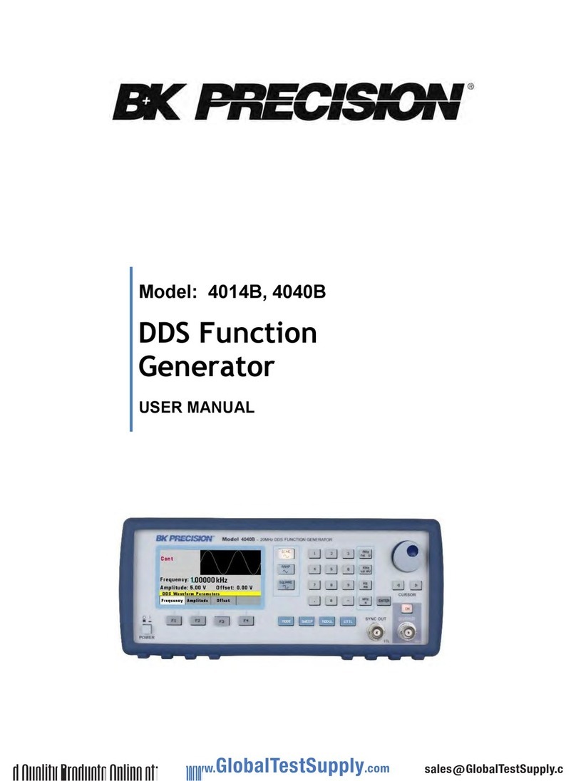
B+K precision 4014B User manual

B+K precision

B+K precision 4014B User manual

B+K precision 4014B User manual

B+K precision

B+K precision 4014B User manual

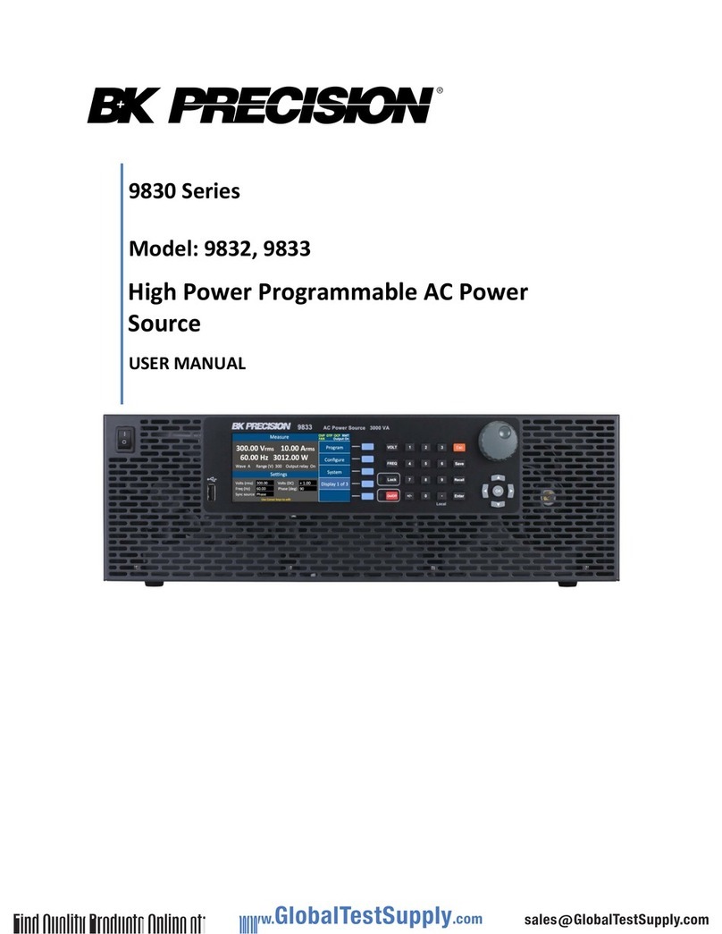
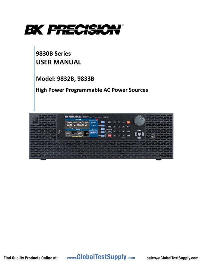
B+K precision 9830B Series User manual

B+K precision

B+K precision 9830B Series User manual

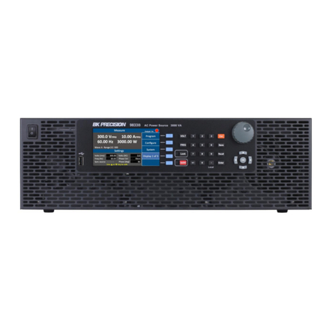
B+K precision 9833B User manual

B+K precision

B+K precision 9833B User manual

B+K precision 4060B Series User manual

B+K precision

B+K precision 4060B Series User manual

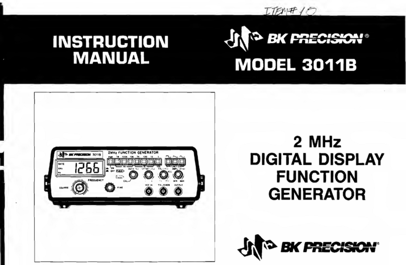
B+K precision 3011B User manual

B+K precision

B+K precision 3011B User manual

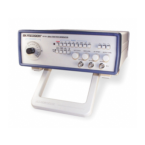
B+K precision 4010A User manual

B+K precision

B+K precision 4010A User manual

B+K precision 9830B Series User manual

B+K precision

B+K precision 9830B Series User manual

B+K precision 4014B User manual

B+K precision

B+K precision 4014B User manual

B+K precision 4075 User manual

B+K precision

B+K precision 4075 User manual

B+K precision 4013DDS User manual

B+K precision

B+K precision 4013DDS User manual

B+K precision 4005DDS User manual

B+K precision

B+K precision 4005DDS User manual

B+K precision 4007B User manual

B+K precision

B+K precision 4007B User manual

B+K precision 4040DDS User manual

B+K precision

B+K precision 4040DDS User manual

B+K precision 9832 User manual

B+K precision

B+K precision 9832 User manual

B+K precision 4040 Manual

B+K precision

B+K precision 4040 Manual

B+K precision BK4053B User manual

B+K precision

B+K precision BK4053B User manual

B+K precision 4075B User manual

B+K precision

B+K precision 4075B User manual

B+K precision 4001A User manual

B+K precision

B+K precision 4001A User manual

B+K precision 4017B User manual

B+K precision

B+K precision 4017B User manual

B+K precision 4017 User manual

B+K precision

B+K precision 4017 User manual

Popular Portable Generator manuals by other brands

Gude GSE 5500 DSG Translation of original operating instructions

Gude

Gude GSE 5500 DSG Translation of original operating instructions

ETQ PG30P11 owner's manual

ETQ

ETQ PG30P11 owner's manual

Rigmaster MTS-T4-LGN owner's manual

Rigmaster

Rigmaster MTS-T4-LGN owner's manual

Dometic GROUP WAECO CoolPower MPS35 Installation and operating manual

Dometic GROUP

Dometic GROUP WAECO CoolPower MPS35 Installation and operating manual

Buffalo Tools GEN4000DF-SS instruction manual

Buffalo Tools

Buffalo Tools GEN4000DF-SS instruction manual

SIGLENT TECHNOLOGIES SDG1062X user manual

SIGLENT TECHNOLOGIES

SIGLENT TECHNOLOGIES SDG1062X user manual

Generac Power Systems 004920-0 owner's manual

Generac Power Systems

Generac Power Systems 004920-0 owner's manual

Bandwidth10 BW10-310A Application note

Bandwidth10

Bandwidth10 BW10-310A Application note

Taurus BT-PG 900 instruction manual

Taurus

Taurus BT-PG 900 instruction manual

Powermate PM0401853 user manual

Powermate

Powermate PM0401853 user manual

Tektronix AFG3000 Series Service manual

Tektronix

Tektronix AFG3000 Series Service manual

Kenwood CG-921 instruction manual

Kenwood

Kenwood CG-921 instruction manual

Ecotricity ECO1800S owner's manual

Ecotricity

Ecotricity ECO1800S owner's manual

DeWalt LaserChalkLine DW088CG instruction manual

DeWalt

DeWalt LaserChalkLine DW088CG instruction manual

Allmand Maxi-Power MP65-8B1 Operator's manual

Allmand

Allmand Maxi-Power MP65-8B1 Operator's manual

Generac Power Systems WheelHouse 5500 owner's manual

Generac Power Systems

Generac Power Systems WheelHouse 5500 owner's manual

Sole Diesel 85 GT Operator's manual

Sole Diesel

Sole Diesel 85 GT Operator's manual

Hyundai power products HY6500SEi user manual

Hyundai power products

Hyundai power products HY6500SEi user manual

manuals.online logo
manuals.online logoBrands
  • About & Mission
  • Contact us
  • Privacy Policy
  • Terms and Conditions

Copyright 2025 Manuals.Online. All Rights Reserved.