B+N INDUSTRIES SYSTEM 1224 User manual
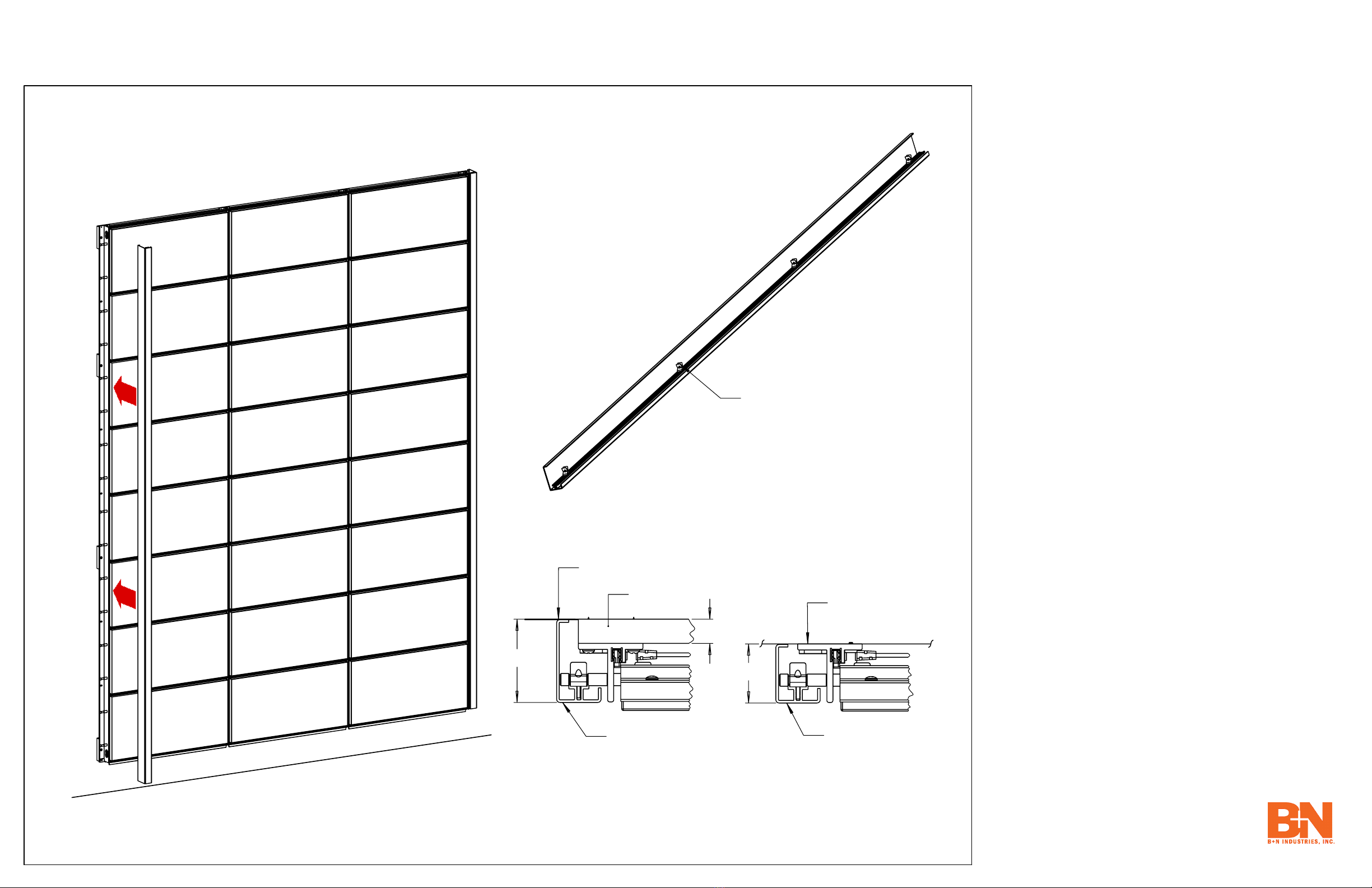
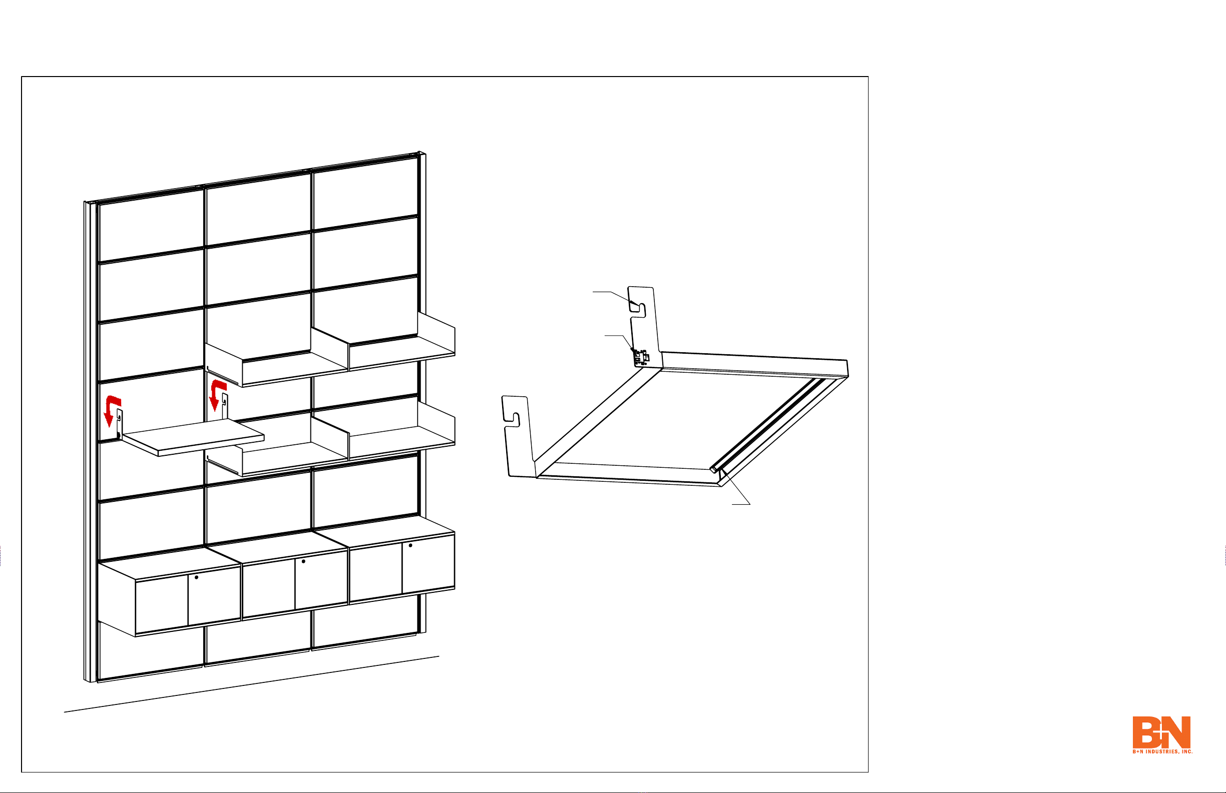
SYSTEM 1224
ASSEMBLY & INSTALLATION
650.593.4127
WWW.BNIND.COM

SYSTEM 1224
SYSTEM OVERVIEW
GENERAL SCOPE:
System 1224 is a highly customizable, grid-based
mechandising system utilizing 8' uprights, panels, and shelving
accessories. A key feature of System 1224 is its "Grid Breaking"
capabilities, allowing different sized panels to be attached in creatve
and expressive ways. System 1224 can aso be electrified adding a
multitude of unique lighting options. This merchandising system's
uprights are braced to a wall, with pins every 6" to attach
accessories like shelves, cabinets, hangbars, and faceouts. The
following pages are instructions for installing a basic System 1224
elevation.
PROVIDED:
(3) Assembly Jigs
(2) 5/32 Allen keys
NOT PROVIDED:
- Hardware to attach to wall (wood screws for furring strips and
recommend #10 pan head screws for attaching uprights).
- Furring Strips
- Cord managment materials like double-stick tape, zip ties, velcro
and other material.
RECOMMENDED TOOLS:
- Hand Drill + necessary drill and driver bits
- Levels
- Tape Measure
SAFETY INSTRUCTIONS:
•For dry locations only.
•Use only with listed Class 2 driver.
•To reduce rish of fire, do not install in a compartment small than
24 inches by 12 inches by 12 inches.
CAUTION!
To reduce the risk of fire, electric shock, or injury to persons:
1.)
Use only insulated staples or plastic ties to secure cords.
2.)
Route and secure cords so that they will not be piched or
damaged when the cabinet or accessory is secured in place.
3.)
Not intended for recessed installation in ceilings or soffits.
4.)
The National Electric Code (NEC) does not permit cords to be
concealed where damage to insulation may go unnoticed. To
prevent fire danger, do not run cords behind walls, ceilings, soffits,
or cabinets where it may be inaccessible for examination. Cords
should be visually examined periodically and immediately replaced
when any damage is noted,
PAGE
1 of 10
8' UPRIGHT W/ PINS
PANEL
(Available in multiple
sizes and materials)
8' ENDCAP
(Available in Shallow & Deep)
ASSEMBLY JIG
DRIVER
TIEBACK
FOOT
SEG GRAPHIC PANEL
(Available in Proud and Flush)
ACCESSORIES
(Most available in 24" & 48",
electrified & non-electrified)
650.593.4127
WWW.BNIND.COM

Secure furring strips to studs in wall.
74.00 O.D.
96.19
6.00
24.00
O.C.
UPRIGHTS
SAMPLE ELEVATION
6.00
34.50
34.50
23.00
74.00 (OVERALL WIDTH)
4.00
4" X .75" FURRING STRIP
Floor
Wall
SYSTEM 1224
FURRING STRIPS
BEFORE YOU BEGIN:
The following instructions will show a three bay
elevation using typical 8' uprights as a sample installation. Although
System 1224 can be secured directly to a suitable substrate wall,
B+N recommends the use of furring strips. Furring strips will insure
a strong and stable installation.
STEP 1:
Determine the overall width of the elevation. This can be
calculated by adding the on-center dimension of the bays plus 1" on
each end. For example a three bay elevation is 24"+24"+24"+1+1"=
74".
STEP 2:
Cut four wood furring strips. Furring strip measurements are
4"H X .75" thick X 74" (length calculated above).
STEP 3:
Locate and mark studs in the wall. Now determine the
starting location of the elevation. The first furring strip will be
installed 6" (recommended) off the floor. Using a level, secure the
furring strip to the wall into the studs.
STEP 4:
Attach the three additional furring strips using the
dimensions shown.
PAGE
2 of 10
10' UPRIGHT
(FLOOR TO WALL SHOWN)
1
234
5
BAY
1
BAY
2
BAY
3
1234
650.593.4127
WWW.BNIND.COM

74.00 O.D.
96.19
6.00
24.00
O.C.
UPRIGHTS
SAMPLE ELEVATION
Step 2:
Attach Upright
SYSTEM 1224
INSTALLING 1ST UPRIGHT
STEP 1:
Hold the upright against the left side of the furring strips.
The bottom left corner of the upright should align with the bottom
left corner of the lowest furring strip.
STEP 2:
Using a level, orient the upright vertically and, using #10
button head wood screws (not included) screw the upright to the
furring strips in the locations marked. The holes in the upright are
slotted allowing for some adjustability. If the furring strips were
properly installed, the edges should align with the left edge of the
upright.
STEP 3:
Before fully seating screws, verify the upright is vertically
level and not bowed. Proceed to next page.
PAGE
3 of 10
10' UPRIGHT
(FLOOR TO WALL SHOWN)
1
234
5
BAY
1
BAY
2
BAY
3
1234
Step 1:
Position Upright
650.593.4127
WWW.BNIND.COM

74.00 O.D.
96.19
6.00
24.00
O.C.
UPRIGHTS
SAMPLE ELEVATION
AR
DETAIL
AR
Step 2: Install the Jig
AS
DETAIL
AS
SCALE
1 : 2
Assembly Jig
(3 included)
SYSTEM 1224
USING ASSEMBLY JIGS
GENERAL SCOPE:
To insure the uprights are installed at the proper
distance apart, B+N provides Assembly Jigs. The jigs are installed
between uprights by removing pins from the uprights, and attaching
the jigs inbetween. The jigs are designed to create a perfect 24" on
center installation; necessary to insure System 1224 functions
properly.
PROVIDED:
3 Spacing Jigs
2 5/32" Allen Keys
STEP 1:
After installing the first upright, gather the three included
Assembly Jigs. Select pins on the installed upright near the top,
middle, and bottom (Labeled A1, B1, and C1) and remove them
using two allen keys. Remove the corresponding pins on the next
upright in a similar fashion (Labeled A2, B2, and C2).
STEP 2:
Slide one of the Assembly Jigs in between the first upright
and the next upright. This is easiest if one person holds the upright
against the furring strips while another installs the jig. Attach one
half of the pin set through one side of the jig, through the upright,
and into the matching pin. Tighten the pin set. Do this for each end
of the jig. Repeat the process for the remaining two jigs. The next
upright is properly spaced to 24" on-center.
STEP 3:
Using levels on the jigs and upright as needed, screw the
next upright into the furring strip and into position where marked.
STEP 4:
After removing the pins holding the jigs in place, remove the
jigs. Some force may be required to pull the jigs out of position.
Replace the three sets of pins on the first upright, but leave the
three sets on the second upright off in preparation for installing the
next jig and upright.
STEP 5:
Install the remaining uprights following the steps above.
PAGE
4 of 10
10' UPRIGHT
(FLOOR TO WALL SHOWN)
A1
2
B1
C1
5
BAY
1
BAY
2
BAY
3
1234
C2
B2
A2
Step 1: Remove Pins
Step 3:
Level &
Attach Upright
650.593.4127
WWW.BNIND.COM

74.00 O.D.
96.19
6.00
24.00
O.C.
UPRIGHTS
SAMPLE ELEVATION
24.00
O.C.
24.00
O.C.
24.00
O.C.
SYSTEM 1224
FINISHING UP
Repeat the steps from the previous page to install all remaining
uprights.
...If the elevation is electrified, continue with the next page
"
Connecting Power.
"
...If the elevation is
not
electrified, please proceed to "
Installing
Panels.
"
PAGE
5 of 10
10' UPRIGHT
(FLOOR TO WALL SHOWN)
1
234
5
BAY
1
BAY
2
BAY
3
1234
650.593.4127
WWW.BNIND.COM

Driver powers Uprights 1 + 2
Driver powers Upright 3
1
2
3
4
1
AT
DETAIL
AT
SCALE
1 : 6
Splitter fed through
mouse hole in upright
Step 3: Splitter
Location 1
Location 2
Location 3
AU
DETAIL
AU
SCALE
1 : 1.4
Screws X2
Copper power channel
Step 2: Power Connector
SYSTEM 1224
CONNECTING POWER
General Scope:
The powering of the uprights is accomplished by
using a driver connected to a power connector, which in turn is
connected to the upright. The power connector makes contact with a
copper channel that runs the length of the upright. The power needs
of the setup will determine how many drivers are necessary to power
the accessories. This example elevation will use a typical setup of
one driver powering two uprights via a splitter.
STEP 1:
There are 3 pre-determined locations for connecting the
power along the upright (see image). Choose the one that best fits
the needs of the setup. Using double stick tape (not included) affix
the driver to the wall, assuring the power cord can reach the wall
outlet.
STEP 2:
Position the power connector into the copper channel on
the first upright, and screw the connector into position. Use
electrical tape, velcro, or wire cords to create a clean wire
management layout.
STEP 3:
Connect a power connector to the next upright. Feed the
wire through a mouse hole and into the splitter coming off the driver.
Again create a tidy wiring layout.
STEP 4:
Because this example setup uses 3 bays (4 uprights), there
is need for one more driver, which only powers the third upright.
There is no need for a splitter. Attach the driver and power
connector as done previously in Steps 2 and 3.
STEP 5:
Connect the driver power cords to the wall outlets. The
setup is now electrified and ready for electrified accessories.
PAGE
6 of 10
10' UPRIGHT
(FLOOR TO WALL SHOWN)
1
234
5
Step 1: Power Connection Locations
650.593.4127
WWW.BNIND.COM

Top
Panels
Middle
Panels
Bottom
Panels
Step 3: Rotate panel, snap into place.
AV
DETAIL
AV
SCALE
1 : 7
Step 2: Slide panel hook onto pins.
Spring Clip
Hook
Horizontal Extrusion
SYSTEM 1224
INSTALLING PANELS
GENERAL SCOPE:
The grid-breaking panels of System 1224 come
in many different sizes and finishes, including electrified SEG
graphic panels. Panels are location specific, labeled Top, Middle, or
Bottom. The difference being the orientation of the horizontal
extrusions on the back surface. Panels are attached by two
hardware types: spring clips and hooks. Most panels have hooks
located in the bottom, with the rest of the hardware being spring
clips, the exeption being Bottom panels which use just spring clips.
The following instructions explain installing a typical 1 foot high by 2
foot wide metal panel.
RECOMMENDED TOOLS:
No tools needed
STEP 1:
Determine which panel will be installed and whether it is
located Top, Middle, or Bottom (see image on left). Panels will be
labeled accordingly.
STEP 2:
Holding the panel at a slight angle, locate the lower hooks
onto the upright pins.
STEP 3:
Rotate the panel up and the spring clips will snap into
position on the uprighjt pins, locking the panel into place. Repeat for
all other panels.
Note:
Bottom panels only use spring clips and are pushed into
posisition straight on.
PAGE
7 of 10
10' UPRIGHT
(FLOOR TO WALL SHOWN)
1
234
5
Back Side of Panel
650.593.4127
WWW.BNIND.COM

Step 1: Snap End Cap into place
Spring Clip
AW
.75
2.58
DETAIL
AW
SCALE
2 : 5
Furring Strip
Wall
Deep End Cap
AX
1.83
DETAIL
AX
SCALE
2 : 5
Wall
Shallow End Cap
SYSTEM 1224
ADDING ENDCAPS
GENERAL SCOPE:
End Caps cleanly finish the System 1224
elevation. They are available in both Shallow and Deep variations.
Deep End Caps are used when the uprights are secured to furring
strips, and Shallow End Caps are used when the uprights are
secured directly to the wall.
RECOMMENDED TOOLS:
No tools needed
STEP 1:
Starting on the left side, orient the End Cap properly so that
the spring clips face the upright pins. Simply push the spring clips on
to the pins and the End Cap will snap into position.
STEP 2:
For the right side, repeat Step 1.
PAGE
8 of 10
10' UPRIGHT
(FLOOR TO WALL SHOWN)
1
234
5
Back Side of End Cap
Top Views of End Caps
650.593.4127
WWW.BNIND.COM

Step 2: Lock accessory into position
J-Hook
Electrical Clip
LED Light
Flat Shelf Example
SYSTEM 1224
ADDING ACCESSORIES
GENERAL SCOPE:
System 1224 has a wide range of shelving and
cabinet accessories, available in 24" and 48" wide, and many of
those also come as electrified lit versions. Adding accessories is
made effortless, utilizing the j-hook feature, and hanging from the
upright pins. Install locations are vertically every 6" along the
upright.
RECOMMENDED TOOLS:
No tools needed
STEP 1:
Determine the location of the accessory. Pin locations are
visible in the gap between the panels and front visible edge of the
upright.
STEP 2:
Position the accessory so that the j-hook on the rear of the
accessory lines up with the desired pin. Slide the accessory into the
gap, with the slots of the j-hooks engaging the pins. Push the
accessory down to lock it into place. If the accessory is electrified,
the LED light will automatically turn on.
Note:
Some accessories, like cabinets, use multiple j-hooks to
support the accessory. They are installed in a similar manner.
PAGE
9 of 10
10' UPRIGHT
(FLOOR TO WALL SHOWN)
1
234
5
650.593.4127
WWW.BNIND.COM

Thank you for choosing
SYSTEM 1224!
650.593.4127 WWW.BNIND.COM
Table of contents