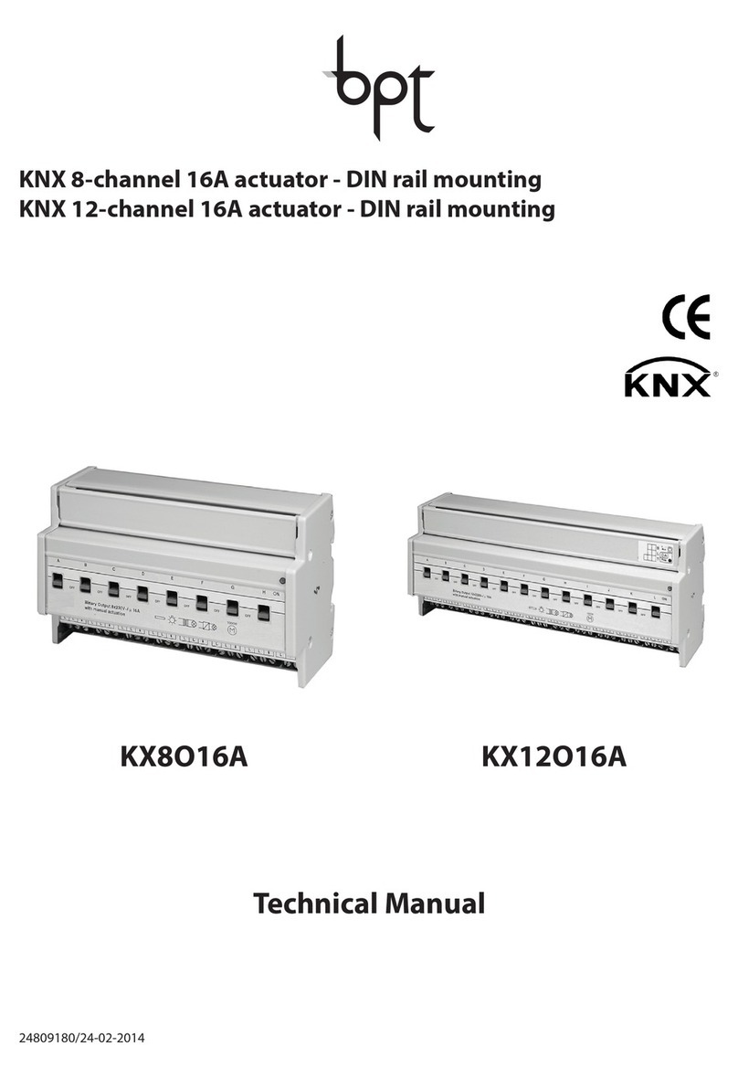
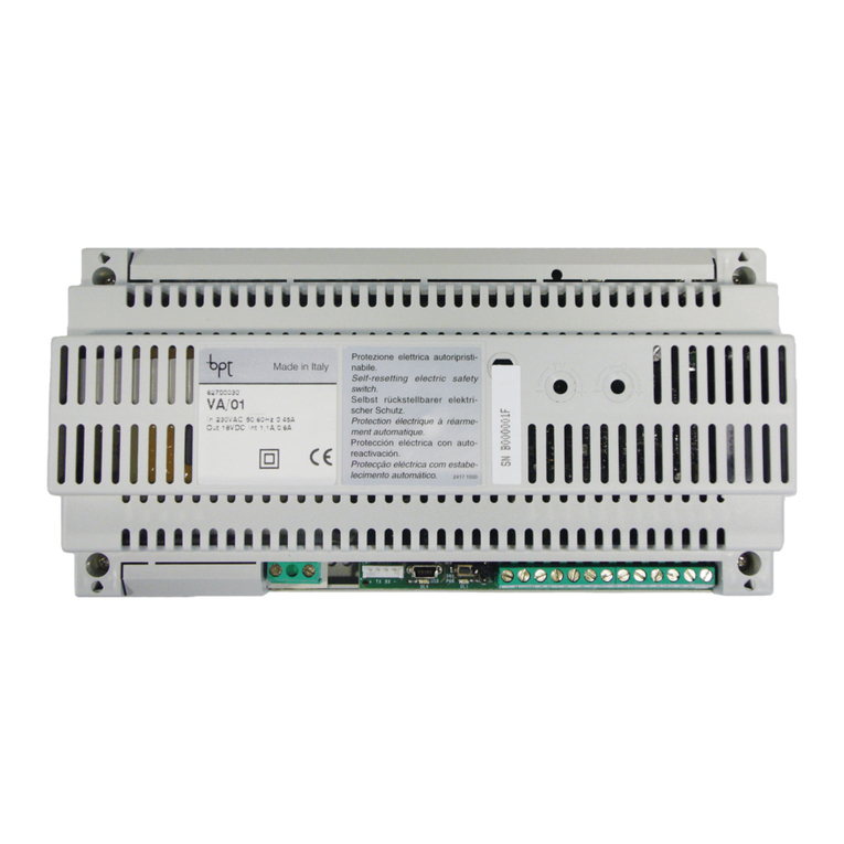
Bpt KX4O16A User manual

KX4O16A
Attuatore 4 canali 16 AX KNX con comando manuale - da guida DIN
KNX 4-c annel 16 AX actuator wit manual control - DIN rail mounting
Actionneur à 4 canaux 16 AX KNX à commande manuelle - sur rail D N
Accionador de 4 canales 16 AX KNX con mando manual - de carril DIN
4-Kanal-Schaltgeber 16AX KNX mit manueller Steuerung - auf D N-Schiene
24808840/20-02-2014

-+
-
+
bus
U
L
N.O.
U
LN.O.
U
L
N.O. LN.O.
U
NN
NN
NL
Bus
230 V
≥ 4 mm
A
B
C
Uscita relè 1 -Output relay 1 - Sortie relais 1 -
Salida relé 1 - Relaisausgang 1
Uscita relè 2 -Output relay 2 - Sortie relais 2 -
Salida relé 2 - Relaisausgang 2
Pulsante comando locale relè 1 -Relay 1 local
command button -
Bouton-poussoir de commande
locale du relais 1
-Pulsador mando local de relé 1
- Lokaler Relaissteuertaster 1
LED stato relè 1 -Relay 1 status LED - LED état du
relais 1 -LED de estado de relé 1 - LED Relaisstatus
1
Pulsante comando locale relè 2 -Relay 2 local
command button -
Bouton-poussoir de commande
locale du relais 2
- Pulsador mando local de relé 2
- Lokaler Relaissteuertaster 2
LED stato relè 2 -Relay 2 status LED - LED état du
relais 2 - LED de estado de relé 2 - LED
Relaisstatus 2
LED stato relè 3
-
Relay 3 status LED - LED état du
relais 3 - LED de estado de relé 3 - LED
Relaisstatus 3
Pulsante comando locale relè 3
-
Relay 3 local
command button -
Bouton-poussoir de commande
locale du relais 3
-Pulsador mando local de relé 3
- Lokaler Relaissteuertaster 3
LED di programmazione indirizzo fisico - LED for
programming p ysical address - LED de
programmation de l’adresse physique - LED de
programación de dirección física - LED für die
Programmierung der physikalischen Adresse
Tasto di programmazione indirizzo fisico - Button
key for programming p ysical address - Touche de
programmation de l’adresse physique - Tecla de
programación de dirección física - Taste fur die
Programmierung der physikalischen Adresse
LED stato relè 4 -Relay 4 status LED - LED état du
relais 4 - LED de estado de relé 4 - LED
Relaisstatus 4
Pulsante comando locale relè 4 -Relay 4 local
command button -
Bouton-poussoir de commande
locale du relais 4
-Pulsador mando local de relé 4
- Lokaler Relaissteuertaster 4`
Uscita relè 3 -Output relay 3 - Sortie du relais
3 - Salida relé 3 - Relaisausgang 3
Uscita relè 4 -Output relay 4 - Sortie du relais
4- Salida relé 4 - Relaisausgang 4
Terminali bus -Bus terminals - Bornes du bus-
Conectores bus - Busanschlüsse
Alimentazione ausiliaria 230 ac -Auxiliary 230Vac
-
Alimentación auxiliar 230 Vca - 230VAC-Hilfsversorgung
2
1
3
4
5
6
1
6
7
8
4
5
3
8
7
9
2
13 14 15
12
10
9
10
11
12
13
14
15
11
16
16

I
T
A
L
I
A
N
O
3
pag.
A ERTENZE GENERALI ................................................................................... 4
DESCRIZIONE GENERALE.................................................................................. 5
INSTALLAZIONE................................................................................................ 7
PROGRAMMAZIONE CON SOFTWARE ETS......................................................... 9
DATI TECNICI.................................................................................................... 10
+
-
bus
N
N
L
ITOT
ITOT ≤ IMAX
Se si utilizzano i doppi morsetti per effettuare l’entra ed esci della fase (L),
verificare che la corrente totale circolante ( TOT) non superi la corrente max ( MAX)
indicata nella sezione “Dati tecnici” del foglio istruzioni.
INDICE

4
Attenzione! La sicurezza dell’apparecchio è garantita solo attendendosi alle
istruzioni qui riportate. Pertanto è necessario leggerle e conservarle. prodotti KNX
BPT devono essere installati conformemente a quanto previsto dalla norma CE 64-8
per gli apparecchi per uso domestico e similare, in ambienti non polverosi e dove
non sia necessaria una protezione speciale contro la penetrazione di acqua.
L’organizzazione di vendita BPT è a disposizione per chiarimenti e informazioni
tecniche.
BPT SpA si riserva il diritto di apportare modifiche al prodotto descritto in questo
manuale in qualsiasi momento e senza alcun preavviso.
n. 1 Attuatore 4 canali 16 AX KNX con comando manuale - da guida D N
n. 1 Morsetto bus
n. 5 Morsetti a vite
n. 1 Coperchietto con vite
n. 1 Manuale di installazione e uso
Contenuto della confezione
AVVERTENZE GENERALI

I
T
A
L
I
A
N
O
5
L’Attuatore 4 canali 16 AX KNX con comando manuale - da guida D N permette di
attivare/disattivare indipendentemente fino a 4 diversi carichi elettrici attraverso 4
relè da 16 AX provvisti di 1 contatto di uscita NA ciascuno. l comando di
commutazione del relè può giungere da dispositivi di comando o sensori del sistema
di Building Automation, tramite il bus KNX, oppure essere generato localmente
mediante i pulsanti frontali.
l dispositivo è provvisto di un ingresso ausiliario 230 Vac che permette di
controllare i carichi collegati attraverso i pulsanti frontali anche in caso di assenza
della tensione bus KNX (con tensione di rete 230 Vac presente).
L’attuatore è alimentato dalla linea bus ed è dotato di 4 LED frontali verdi per la
segnalazione di stato delle uscite. l dispositivo invia sul bus informazioni sullo stato
del relè (ON = contatto chiuso, OFF = contatto aperto) all’accensione, alla ricezione
di un comando ed in caso di comando da pulsante locale.
Ogni canale di uscita dell’attuatore può essere configurato in modo indipendente e
permette il comando ON/OFF dei carichi comandati, l’esecuzione di comandi
temporizzati, la gestione di scenari e l’esecuzione di comandi prioritari per la
forzatura dello stato dell’uscita. Le modalità di funzionamento sono fruibili
contemporaneamente attraverso oggetti di comunicazione distinti.
Ciò significa, ad esempio, che il dispositivo può accendere e spegnere una luce,
oppure accenderla e spegnerla automaticamente dopo che è trascorso un certo
tempo prefissato, semplicemente in funzione del comando ricevuto.
l modulo viene montato su guida D N, all’interno di quadri elettrici o scatole di
derivazione.
In breve
DESCRIZIONE GENERALE

6
Funzioni
L’attuatore viene configurato con il software ETS per realizzare le funzioni elencate
qui di seguito.
Commutazione:
- parametrizzazione comportamento uscite (NA/NC)
- temporizzazione luci scale con possibilità di impostare la durata della
temporizzazione via bus
- temporizzazione luci scale con funzione di preavviso allo spegnimento
- ritardo all’attivazione/disattivazione
- lampeggio
Scenari:
- memorizzazione ed attivazione di 8 scenari (valore 0-63) per ogni uscita
- abilitazione/disabilitazione memorizzazione scenari da bus
Comandi prioritari:
- parametrizzazione del valore relè di uscita al termine della forzatura
Comando di blocco:
- parametrizzazione valore oggetto di blocco e valore relè di uscita alla fine del
blocco
Funzioni di sicurezza:
- monitoraggio periodico oggetto di ingresso
Funzioni logiche:
- operazione logica AND/NAND/OR/NOR con oggetto di comando
(commutazione, commutazione temporizzata, commutazione ritardata,
lampeggio) e risultato operazione logica
- utilizzo del risultato dell'operazione logica per abilitazione oggetto di comando
(commutazione, commutazione temporizzata, commutazione ritardata,
lampeggio, scenario)
- operazioni logiche AND/NAND/OR/NOR/XOR/XNOR fino a 4 ingressi logici
Stato uscita:
- invio su bus parametrizzabile
Altre funzioni:
- parametrizzazione comportamento uscita alla caduta/ripristino tensione su bus
- parametrizzazione comportamento pulsanti di comando locale
DESCRIZIONE GENERALE

I
T
A
L
I
A
N
O
7
ATTENZIONE: l’installazione del dispositivo deve essere effettuata
esclusivamente da personale qualificato, seguendo la normativa
vigente e le linee guida per le installazioni KNX.
1.La lunghezza della linea bus tra l’attuatore e l’alimentatore non deve superare i
350 metri.
2.La lunghezza della linea bus tra l’attuatore e il più lontano dispositivo KNX non
deve superare i 700 metri.
3.Per evitare segnali e sovratensioni non voluti, non dar vita a circuiti ad anello.
4.Mantenere una distanza di almeno 4 mm tra i cavi singolarmente isolati della
linea bus e quelli della linea elettrica (figura C).
5.Non danneggiare il conduttore di continuità elettrica della schermatura (figura
D).
ATTENZIONE: i cavi di segnale del bus non utilizzati e il conduttore di
continuità elettrica non devono mai toccare elementi sotto tensione o
il conduttore di terra!
Montare l’attuatore 4 canali su guida DN da 35 mm nel seguente modo (figura E):
1.nserire l’aggancio superiore del dispositivo nella guida DN.
2.Ruotare il dispositivo e bloccarlo sulla guida DN agendo sulla linguetta di
fissaggio.
Avvertenze per l’installazione KNX
Montaggio su guida DIN
INSTALLAZIONE

8
ATTENZIONE: disinserire la tensione di rete prima di connettere il
dispositivo alla rete elettrica!
La figura Bmostra lo schema delle connessioni elettriche.
1. Connettere il filo rosso del cavo bus al morsetto rosso (+) del terminale e il filo
nero al morsetto nero (-). Al terminale bus si possono collegare fino a 4 linee
bus (fili dello stesso colore nello stesso morsetto) (figura F).
2. solare lo schermo, il conduttore di continuità elettrica e i rimanenti fili bianco e
giallo del cavo bus (nel caso in cui si utilizzi un cavo bus a 4 conduttori), che
non sono necessari (figura D).
3. nserire il morsetto bus negli appositi piedini del dispositivo. l corretto senso di
inserzione è determinato dalle guide di fissaggio. solare il morsetto bus usando
l’apposito coperchietto, che deve essere fissato al dispositivo con la sua vite.
l coper chietto garantisce la separazione minima di 4 mm tra i cavi di potenza e
i cavi bus (figura G).
4. Collegare i carichi agli appositi morsetti a vite in dotazione, controllando di non
superare i limiti di corrente specificati nei Dati tecnici. nserire i morsetti nei
connettori di uscita dell'attuatore, prestando attenzione al loro corretto
inserimento (figura H).
Connessioni elettriche
pulsanti di comando locale (figura A) consentono di effettuare la commutazione
ciclica ON/OFF, invertendo lo stato del relè ad ogni loro pressione (impostazione di
default).
Nel caso in cui sia attivo un comando prioritario, i comandi locali non sono eseguiti.
E' possibile configurare il comportamento del pulsante di comando locale via ETS.
ATTENZIONE: i pulsanti di comando locale sono funzionanti anche in
assenza della tensione del BUS, purché sia presente l'alimentazione
ausiliaria 230Vac.
Uso del pulsante di comando locale
Manutenzione
l dispositivo non necessita di manutenzione. Per un’eventuale pulizia adoperare un
panno asciutto.
INSTALLAZIONE

I
T
A
L
I
A
N
O
9
l dispositivo deve essere configurato con il software ETS.
nformazioni dettagliate sui parametri di configurazione e sui loro valori sono
contenute nel Manuale Tecnico.
PROGRAMMAZIONE CON SOFTWARE ETS

10
Comunicazione Bus KNX
Alimentazione Tramite bus KNX, 29 V dc SELV
Alimentazione ausiliaria 230Vac
Cavo bus KNX TP1
Assorbimento corrente dal bus 10 mA max
Elementi di comando 1 tasto miniatura di programmazione
4 pulsanti di comando locale dei relè
Elementi di visualizzazione 1 LED rosso di programmazione
4 LED verdi di segnalazione stato uscita
Elementi di attuazione 4 relè 16 AX con contatto NA libero da tensione
Corrente max di commutazione 16 A (AC1)
16AX (140 µF rif. EN 60669-1) carichi
fluorescenti con corrente massima di spunto 400A (200 µs)
Potenza max per tipologia carico Lampade a incandescenza (230Vac): 3000W
Lampade alogene (230Vac): 3000W
Carichi pilotati da trasformatori toroidali: 3000W
Carichi pilotati da trasformatori elettronici: 2000W
Lampade a basso consumo
(fluorescenti compatte): 80x23W
Potenza massima dissipata 5 W
Ambiente di utilizzo nterno, luoghi asciutti
Temperatura di funzionamento -5 ÷ +45 °C
Temperatura di stoccaggio -25 ÷ +70 °C
Umidità relativa Max 93% (non condensante)
Connessione al bus Morsetto ad innesto, 2 pin Ø 1 mm
Connessioni elettriche Morsetti estraibili a vite, sezione max cavi: 4 mm2
Grado di protezione P20
Dimensione 4 moduli D N
Riferimenti normativi Direttiva bassa tensione 2006/95/CE
Direttiva compatibilità elettromagnetica
2004/108/CE, EN50428, EN50090-2-2
Certificazioni KNX
DATI TECNICI

I
T
A
L
I
A
N
O
11

12
page
GENERAL WARNINGS ....................................................................................... 13
GENERAL DESCRIPTION.................................................................................... 14
INSTALLATION ................................................................................................. 16
PROGRAMMING WITH ETS SOFTWARE ............................................................. 18
TECHNICAL DATA ............................................................................................ 19
+
-
bus
N
N
L
ITOT
ITOT ≤ IMAX
f the dual terminals are used for phase (L) entry and exit, check that the total
circulating current ( TOT) does not exceed the max current ( MAX) indicated in the
"Technical data" section of the instruction sheet.
INDEX

13
E
N
G
L
I
S
H
Warning! The safety of this appliance is only guaranteed if all the instructions given
here are followed scrupulously.
These should be read thoroughly and kept in a safe place.
KNX BPT products can be installed in environments which are dust-free and where
no special protection against the penetration of water is required.
They shall be installed in compliance with the requirements for household devices
set out by the national standards and rules applicable to low-voltage electrical
installations which are in force in the country where the products are installed, or,
when there are none, following the international standard for low-voltage electrical
installations EC 60364, or the European harmonization document HD 60364.
BPT sales organization is ready to provide full explanations and technical data on
request.
Pack Contents
n. 1 KNX 4-channel 16 AX actuator with manual control - D N rail mounting
n. 1 Bus terminal
n. 5 Screw terminals
n. 1 Cover with screw
n. 1 User and installation manual
GENERAL WARNINGS

The KNX 4-channel 16 AX actuator with manual control - D N rail mounting allows
up to 4 different electrical loads to be activated/deactivated separately by means of
4 x 16 AX relays, each one fitted with 1 NO output contact. The relay switchover
command can come from command devices or sensors of the Building Automation
system via the KNX bus or generated locally via the front push-buttons.
The device has an auxiliary 230Vac input that makes it possible to control connected
loads through the front push-buttons also without KNX BUS voltage (with 230Vac
mains voltage present).
The actuator is powered from the BUS line and is equipped with 4 front green LEDs
for signalling the output status. The device sends information to the bus about the
relay status (ON = contact closed, OFF = contact open) when switching on,
receiving a command and in the case of a command from a local push-button.
Each output channel of the actuator can be configured separately and allows the
ON/OFF command of the controlled loads, execution of timed commands, scene
management and execution of priority commands to force the output status. The
functioning modes can be used simultaneously by means of distinct communication
objects.
This means, for instance, that the device can switch a light on and off, or
automatically switch it on and off after a certain pre-established time, simply on
the basis of the command received.
The module is assembled on the D N rail, inside the electric boards or junction
boxes.
14
Briefly
GENERAL DESCRIPTION

The actuator is configured with the ETS software to create the functions listed below.
Switchover:
- parameterisation of output behaviour (NO/NC)
- timing of stair lights and the possibility of setting its duration via the BUS
- timing of stair lights with switch-off warning function
- delayed activation/deactivation
- blinking
Scenes:
- memorisation and activation of 8 scenes (value 0 - 63) for each output
- enabling/disabling storing of scenes by the BUS
Priority commands:
- parameterisation of the output relay value at the end of forcing
Blocking command:
- parameterisation of the blocking object value and output relay value at the end
of blocking
Safety functions:
- periodical monitoring of input object
Logical functions:
- AND/NAND/OR/NOR logical operation with command object (switchover, timed
switchover, delayed switchover, blinking) and result of the logical operation
- using the result of the logical operation to enable the command object
(switchover, timed switchover, delayed switchover, blinking, scene)
- logic operations AND/NAND/OR/NOR/XOR/XNOR up to 4 logic inputs
Output status:
- parameterisable sending to the BUS
Other functions:
- parameterisation of output behaviour with voltage fall/reset on BUS
- parameterisation of behaviour of local command push-buttons
15
E
N
G
L
I
S
H
Functions
GENERAL DESCRIPTION

16
ATTENTION: the device must only be installed by qualified personnel,
observing current regulations and the guidelines for KNX installations.
1.The length of the bus line between the actuator and the power supply must not
exceed 350 metres.
2.The length of the bus line between the actuator and the furthest away KNX device
must not exceed 700 metres.
3.To avoid unwanted signals and overvoltages do not use ring circuits.
4.Keep a distance of at least 4mm between the individually insulated cables of the
bus line and those of the electricity line (figure C).
5.Do not damage the electrical continuity conductor of the shielding (figure D).
ATTENTION: The bus signal cables that are not used and the electrical
continuity conductor must never touch any live elements or the
earthing conductor!
Mount the 4-channel actuator on a 35mm DN rail in the following way (figure E):
1.nsert the upper device coupling in the DN rail.
2.Turn the device and lock it on the DN rail, using the fixing tab.
Recommendations for installing the KNX
Assembly on the DIN rail
INSTALLATION

ATTENTION: disconnect mains voltage before connecting the device to
the mains!
Figure B shows a diagram of the electrical connections.
1. Connect the red wire of the bus cable to the red terminal (+) of the terminal and
the black wire to the black terminal (-). Up to 4 bus lines can be connected to
the bus terminal (same coloured wires on the same terminal) (figure F).
2. nsulate the shield, the electrical continuity conductor and the other white and
yellow wires of the bus cable (if a 4-conductor bus cable is being used), that are
not necessary (figure D).
3.
nsert the bus terminal in the device's pins. The correct insertion direction is
determined by the fixing guides. nsulate the bus terminal with the cover to be
screwed onto the device.
The cover guarantees the minimum separation distance of 4mm between the
power cables and the bus cables (figure G).
4. Connect the loads to the relevant supplied screw terminals, making sure the
current limits specified in the Tec nical Data are not exceeded. nsert the
terminals in the actuator output connectors, and check they are correctly inserted
(figure H).
17
E
N
G
L
I
S
H
Electric connections
With the local command push-buttons (figure A) you can control cyclic ON/OFF
switching over, reversing the status of the relay each time it is pressed (default
setting).
f a priority command is active, the local commands will not be executed.
t is possible to configure the behaviour of the local command push-button via ETS
ATTENTION: the local control push-buttons operate also without BUS
voltage, providing that the auxiliary 230Vac voltage is present.
Using the local command push-button
Maintenance
The device does not require any maintenance. Use a dry cloth if cleaning is
required.
INSTALLATION

The device must be configured with the ETS software.
Detailed information about the configuration parameters and their values can be
found in the Technical Manual
18
PROGRAMMING WITH ETS SOFTWARE

Communication KNX Bus
Power supply via the KNX bus, 29 V dc SELV
Auxiliary power supply 230Vac
Bus cable KNX TP1
Bus current consumption 10 mA max
Command elements 1 miniature programming key
4 push-buttons for local relay command
Display elements 1 red programming LED
4 green LEDs for signalling output status
Actuation elements 4 16AX relays with NO potential free contact
Maximum switchover current 16 A (AC1)
16AX (140 µF ref. EN 60669-1) fluorescent loads
with maximum surge current 400A (200 µs)
Maximum power for load type ncandescent lamps (230 Vac): 3000W
Halogen lamps (230Vac): 3000W
Loads controlled by toroidal transformers: 3000W
Loads controlled by electronic transformers: 2000W
Low consumption lamps
(compact fluorescent lamps): 80x23W
Maximum dissipated power 5W
Ambit of use ndoors, dry places
Operating temperature -5 to +45 °C
Storage temperature -25 to +70 °C
Relative humidity Max 93% (non condensative)
Bus connection Coupling terminal, 2 pins Ø 1 mm
Electrical connections
Extractable screw terminals, maximum cable
section: 4mm2
Protection ratings P20
Dimension 4 D N modules
Reference standard Low voltage directive 2006/95/EC
Electromagnetic Compatibility Directive
2004/108/EC, EN50428, EN50090-2-2
Certifications KNX
19
E
N
G
L
I
S
H
TECHNICAL DATA

20
Table of contents
Languages:
Other Bpt Controllers manuals
Popular Controllers manuals by other brands

vissonic
vissonic VIS-CATC-B user manual

Tornatech
Tornatech MPA Installation and maintenance manual

MegaPoints Controllers
MegaPoints Controllers Servo Controller user guide

Tescom
Tescom RMP-X1 Installation and user guide

Tradinco
Tradinco 8810 user manual

REACIONA
REACIONA AVR-A-OPT-02 Installation and operation manual