Contents
Condenser Microphones . . . . . . . . . . . . . . . . . . . . . . . . . . . . . . . . . . . . . . . . . . . . . . 3
General . . . . . . . . . . . . . . . . . . . . . . . . . . . . . . . . . . . . . . . . . . . . . . . . . . . . . . . . . 3
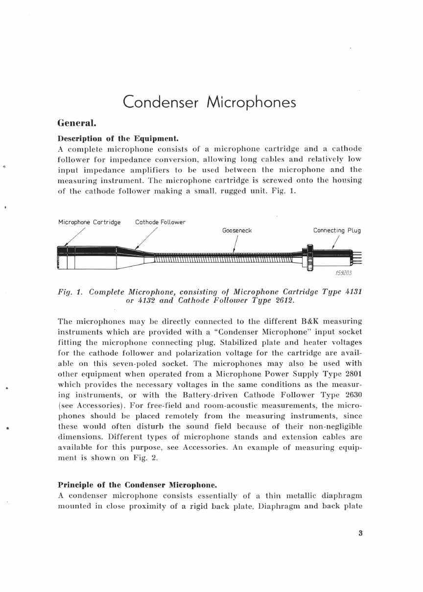
Description
of
the
Equipment
. . . . . . . . . . . . . . . . . . . . . . . . . . . . . . . . . . . . 3
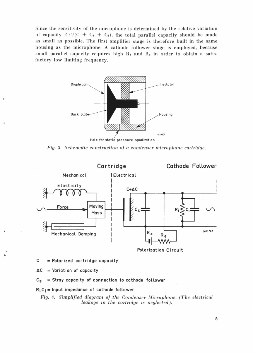
Principle
of
the
Condenser
Microphone
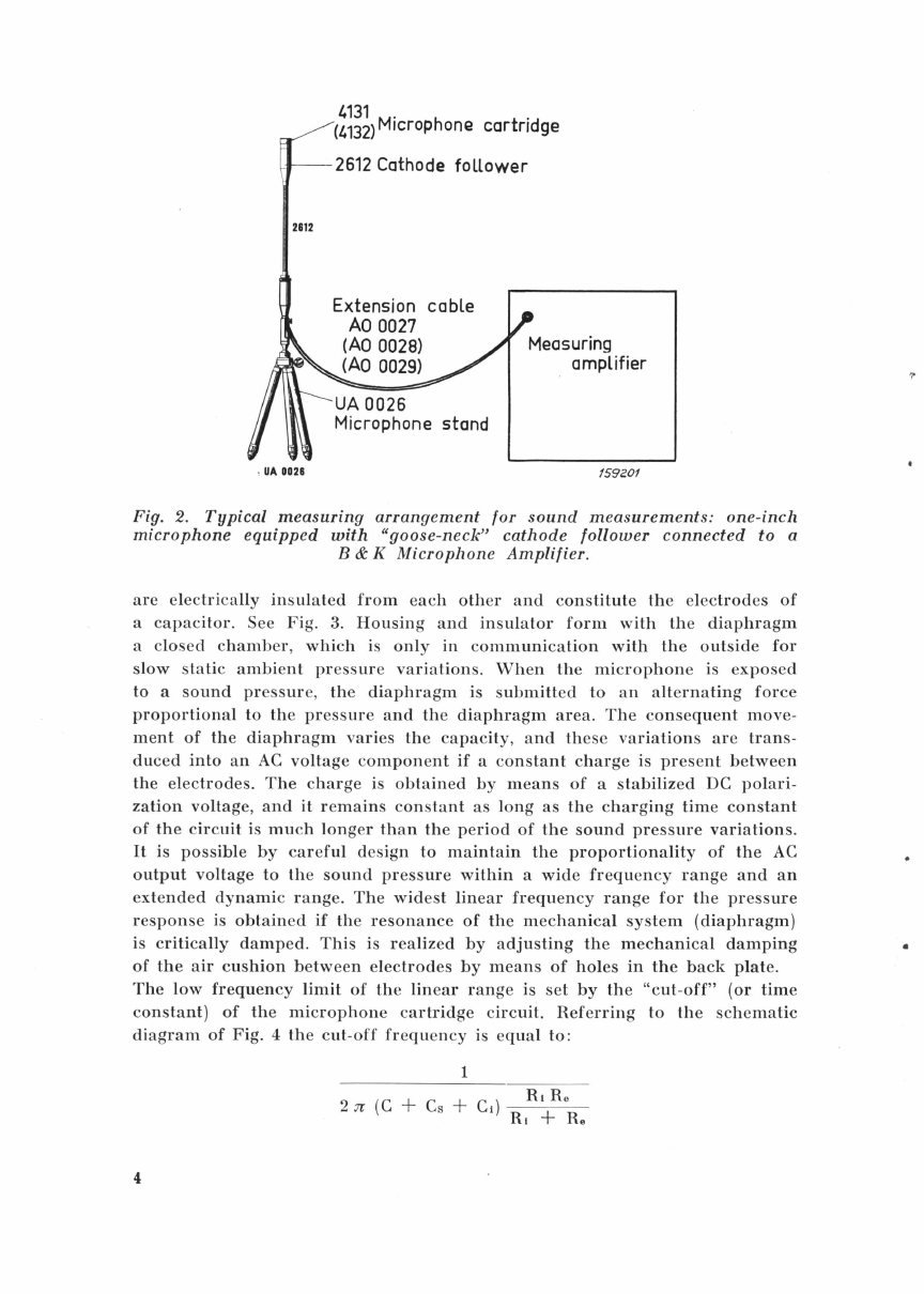
. . . . . . . . . . . . . . . . . . . . . . . . . . 3
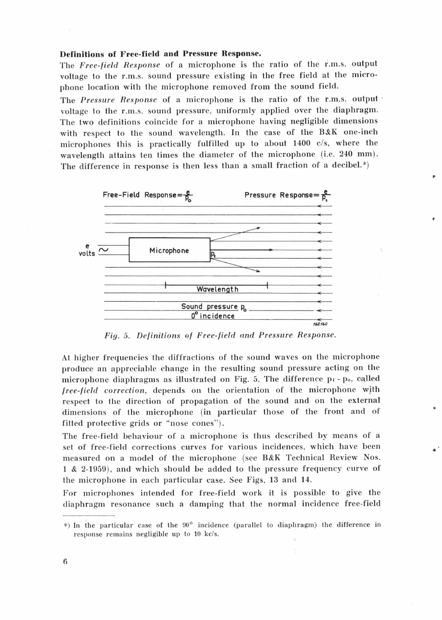
Definition
of
Free-Field
and
Pressure
Response
. . . . . . . . . . . . . . . . . . . . 6
Random
Incidence
Response
. . . . . . . . . . . . . . . . . . . . . . . . . . . . . . . . . . . . . . 'l
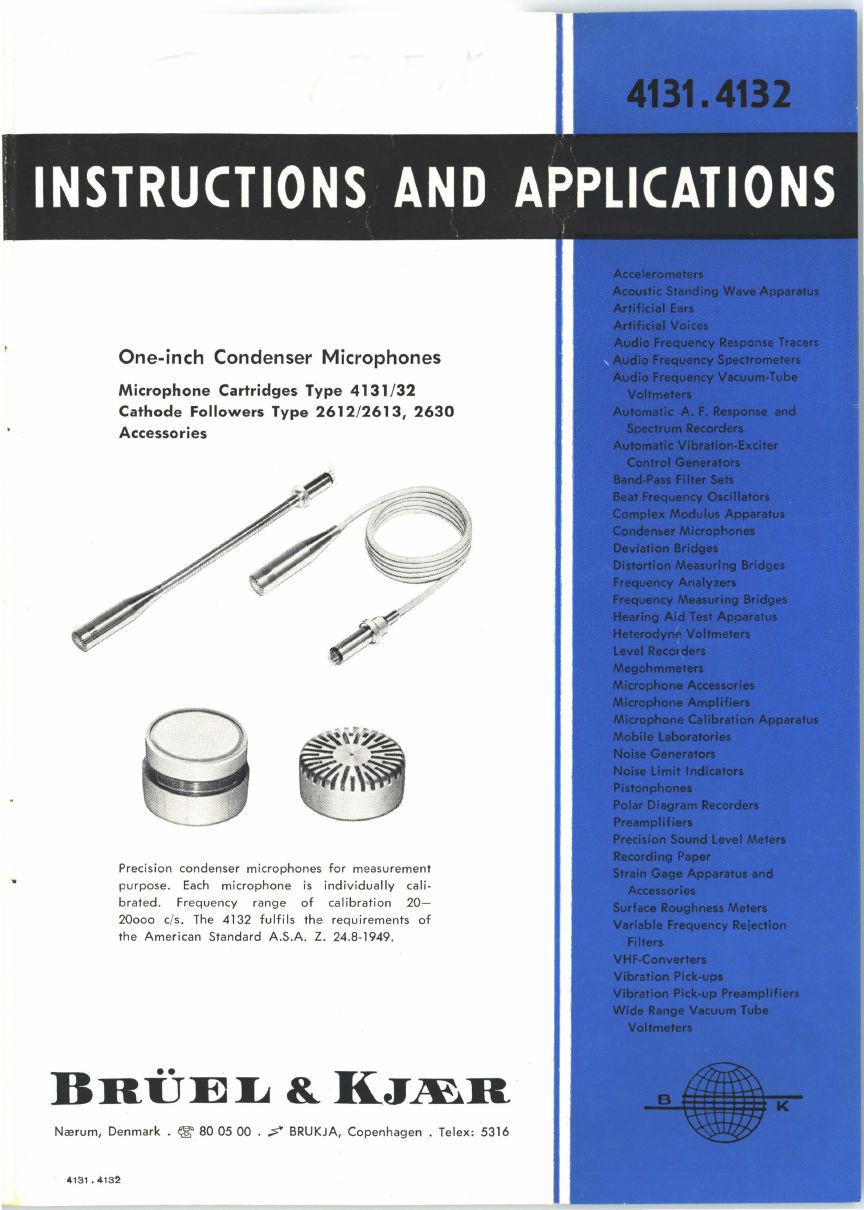
Description:
Microphone
Cartridges
4131-4132
. . . . . . . . . . . . . . . . . . . . 7
Cathode
Followers
2612-2613 . . . . . . . . . . . . . . . . . . . . . . . . 9
General Characteristics:
1.
Sensitivity
...................................................
13
2.
Frequency
Response
.......
.
......
..
..........................
14
3.
Phase
Characteristics
........................................
15
4.
Free
Field
Corrections
........................................
15
5.
Directional
Characteristics
....................................
16
6.
Dynamic
Range,
Noise
and
Distortion
........................
18
7.
Equivalent
Volume
..........................................
19
8.
Influence
of
the
Polarization
Voltage
. . . . . . . . . . . . . . . . . . . . . . . . . . 19
9.
Temperature
. . . . . . . . . . . . . . . . . . . . . . . . . . . . . . . . . . . . . . . . . . . . . . . . . 20
10.
Static
Ambient
Pr
ess
ure
......................................
21
11.
Magnetic
Fields
. . . . . . . . . . . . . . . . . . . . . . . . . . . . . . . . . . . . . . . . . . . . . . 22
12.
Vibrations
...................................................
22
13.
Humidity
....................................................
23
Modification
of
the
pressure
equalization
..........................
24
Comparison
Type
4132 -
Type
WE
640
AA
........................
25
Accessories . . . . . . . . . . . . . . . . . . . . . . . . . . . . . . . . . . . . . . . . . . . . . . . . . . . . . . . . . . 26
Random
Incidence
Corrector
UA 0055
..
.
...........................
26
Wind
Screen
and
Nose
Cone,
UA 0050, UA 0051
...•................
28
Microphone
Stands
UA 0026,
UA
4122
..............................
31
Extension
Cabl~s
AO
0027-28-29,
AR 0001
........................
31
Adaptor
UA
0030
................................................
32
Flexible
Extension
Rod
UA
0039
..................................
32
Couplers
DB
0138-160-161
......................................
32
Two-Channel
Selector
4408
........................................
33
Microphone
Power
Supply
2801
................................
,
...
34
Cathode
Follower
2630
.................................
.
........
35
Microphone Calibration . . . . . . . . . . . . . . . . . . . . . . . . . . . . . . . . . . . . . . . . . . . . . . 38
(Pistonphone
4220,
Microphone
Calibration
Apparatus
4142,
Electrostatic
Actuator
UA
0023,
Noise
Source
4240)
Cathode
Followers
Part Numbers
....................................
41