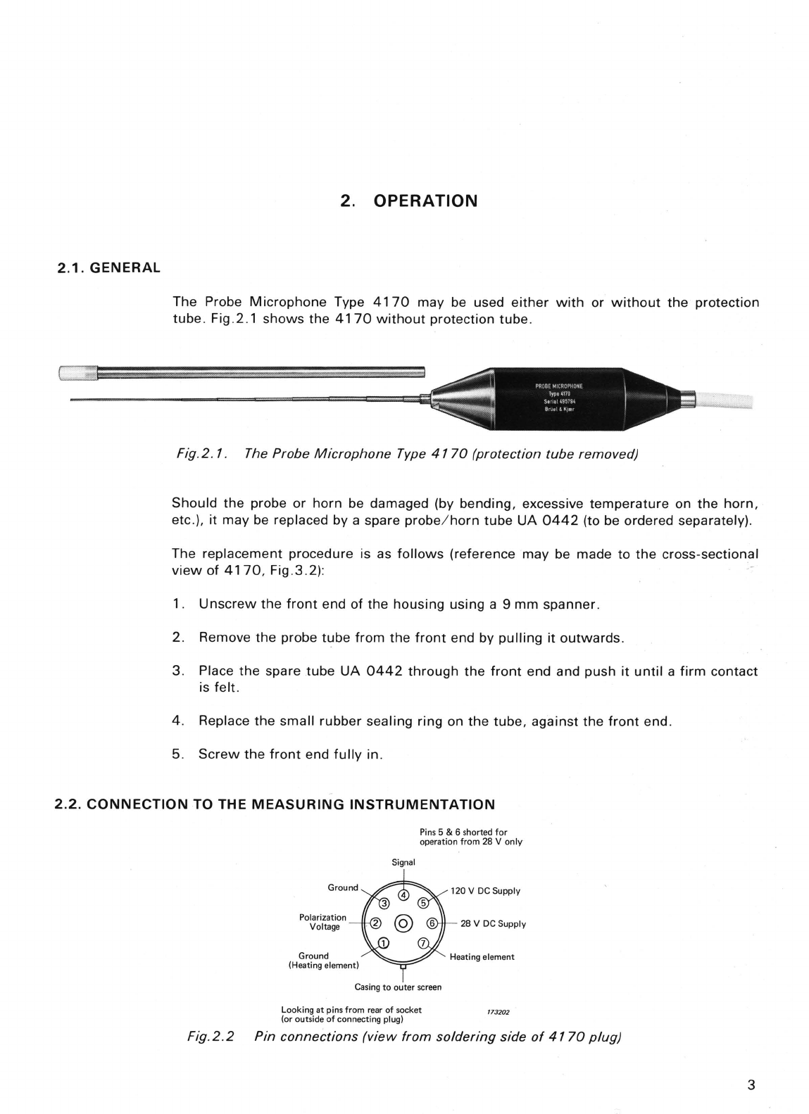
Type
4170
connects
directly
to
the
PREAMP. INPUT
of
B & K
Measuring
Amplifiers
, Fre-
quency
Analyzers, Spectrometers and Power Supplies, via a standard
7-pin
plug
JP
0701.
The pin
connections
are
shown
in Fig.
2.2.
2.3.
CALIBRATION
4
Calibration
Chart
for
Probe Microphone
Type
4170
Se
,ial
No.
"1.:3~
.
1
.
"
.
Sensitiv
i
ty
at
250
Hz
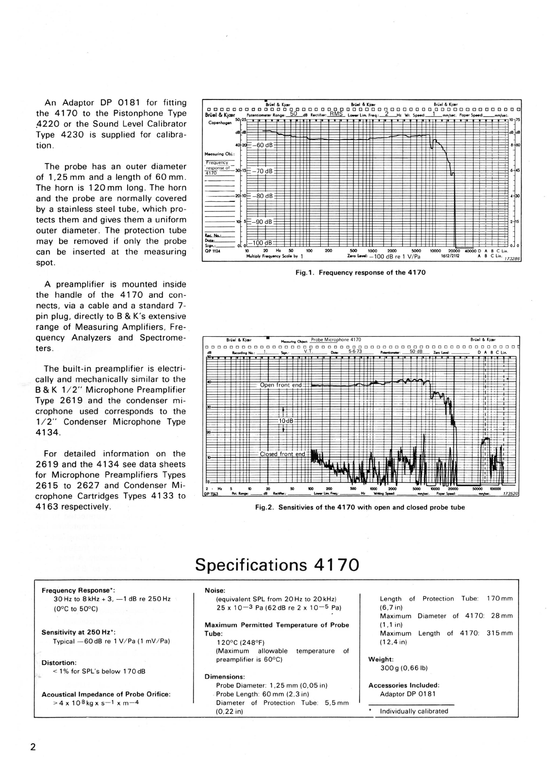
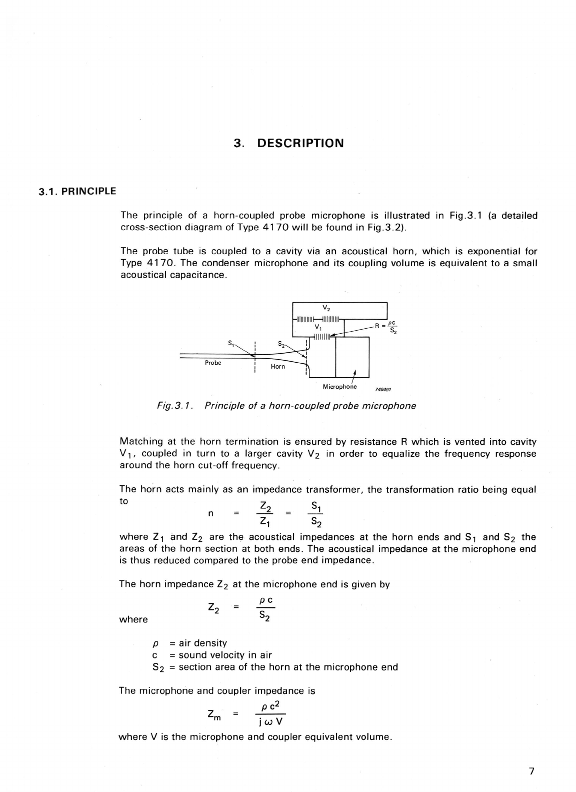
The Probe
Microphone
is i
ndividually
calibrated at
the
factory and is delivered
with
a cali-
bration
chart
giving the
sensitiv
ity at
250
Hz
and
the
frequency
response curve. See
Fig.2.3.
Bruel &
Kimr
Bruel & Kimr Bruel &
Kimr
OOOOOOODOODOOOOOOOOOODOOOOOOoooooooooooooooOOOOOO[
Bruel&Kicer
Potentiometer
Range:
__
dB Rectifier:
__
Lowe
r Lim. Freq.:
__
Hz
Wr
. Speed:
__
mm
/sec.
PaperSpeed
:
_mm
/sec.
IIrileI&KjIor
..
dB
o
- 5
.............
.1.
.4 mV/
Pa
- 10
41
70
is used
in
connection
with
a Bruel
& Kj
ce
r
measuring
amp
lif
ier
for
micro
-
phones
Date
....
19,3,74
...............
. -
15
Si
gnatur
e:
.
~
..
.
~
..
...
Be
0088
QP
1124
-20
10
20
Hz
50
100
200
Multiply
Fr
equency
Scale by
500
1000
2000
Zero Level:
-----
Fig
.2.3. Typical calibration chart
5000
10000
20000
40000D
ABC
lin
.
1612
/
2112
ABC
Lin.
740497
Knowing
the
sensitivity
.
it
is possible
to
calibrate
the
measuring
instrument
using
the
in-
ternal
reference voltage. For
this
type
of
calibration, reference should be made
to
the
in-
struction
manual
for
the
measuring
instrument
in
use.
However,
it
is preferable to calibrate
the
whole
measuring
system
from
probe orifice
to
display device. For
this
purpose, the
Adaptor
DB
0181
is supplied
with
the Probe
Micro-
phone. It
fits
both
the
Pi
stonphone
Type
4220
and the Sound Level Calibrator Type
4230
. The Pistonphone produces a
nominal
sound pressure level
of
124
dB reo
20
pPa
at
250
Hz
wi
th
an accuracy
of
±
0,2
dB. The Sound Level Calibrator produces
94
dB re
20pPa
at 1 kHz
with
an accuracy
of
±0,
25
dB. #
For calibrating a
measur
ing system,
fit
the,
Adaptor
DB
0181
to the
4220
or
4230
and
push
the
probe
fully
into
the
Adaptor
. The calibration procedure depends upon
the
meas-
uring
instrument
in use and reference should be made
to
the
relevant
instruction
man-
ual.
Note:
When
using the
Sound
Level Calibrator Type
4230,
attention
should be paid
to
the
frequency
response curve given by
the
individual calibration
chart
of
the
4170,
since
the
response at 1 kHz may be
higher
than
at
250
Hz. For example, the calibration
chart
of
Fig .2.3 exhibits a +
1,5
dB
amplification
at
1 kHz (compared to
the
250
Hz
level), and a
correction
factor
of
-1,5
dB
must
therefore
be used
when
calibrating a system using
Type
4~30
.