Contents
0. Introduction
Purpose
of
the
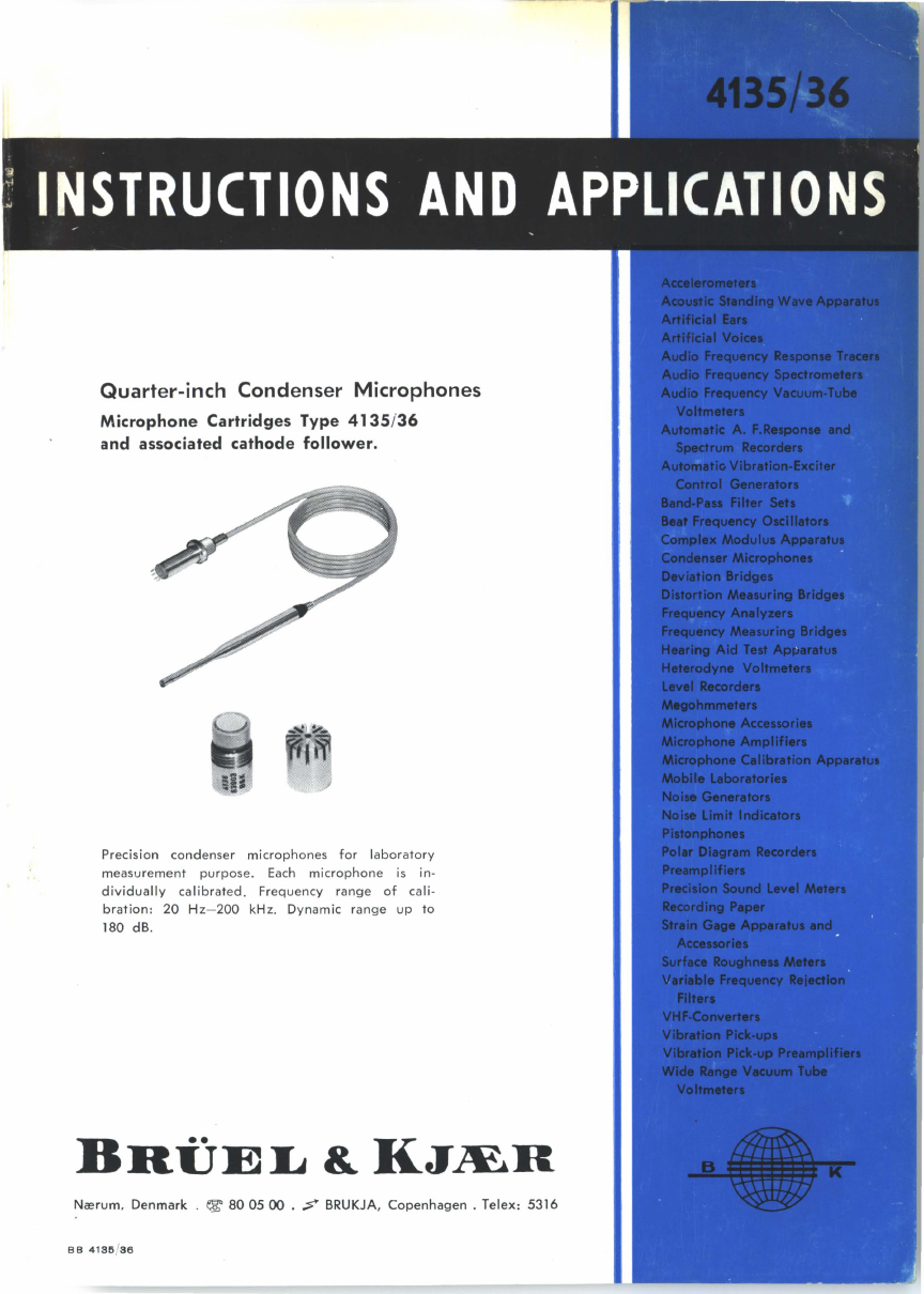
Quarter-inch
Microphones
. . . . . . . . . . . . . . . . . . . . . . . . 3
Principle
of
the
Condenser
Microphone
. . . . . . . . . . . . . . . . . . . . . . . . . . . . 3
Definitions
of
Free-field
and
Pressure
Response
. . . . . . . . . . . . . . . . . . . . 5
Random
Incidence
Response
(Diffuse
Field
Response)
. . . . . . . . . . . . . . 6
1.
Description
General
Description
of
the
Equipment
. . . . . . . . . . . . . . . . . . . . . . . . . . . . 7
Quarter-inch
Condenser
Microphone
Cartridges
. . . . . . . . . . . . . . . . . . . . 8
Cleansing
of
the
Microphone
Diaphragm
. . . . . . . . . . . . . . . . . . . . . . . . . .
11
Associated
Cathode
Follower
Type
2615 +
UA
0035
................
11
Characteristics
of
the
Quarter
-
inch
Microphones
. . . . . . . . . . . . . . . . . .
15
1.
Sensitivity
. . . . . . . . . . . . . . . . . . . . . . . . . . . . . . . . . . . . . . . . . . . . . . . . . . . 15
2.
Frequency
Response
. . . . . . . . . . . . . . . . . . . . . . . . . . . . . . . . . . . . . . . . . 17
3.
Pha
se
Characteristics
and
Pulse
Responses
. . . . . . . . . . . . . . . . . . . . 17
4.
Free
Field
Corrections
........................................
19
5.
Directional
Characteristics
. . . . . . . . . . . . . . . . . . . . . . . . . . . . . . . . . . . .
22
6.
Dynamic
Range
(
Noise
and
Distortion)
. . . . . . . . . . . . . . . . . . . . . . . . 22
7.
Equivalent
Air
Volume
. . . . . . . . . . . . . . . . . . . . . . . . . . . . . . . . . . . . . .
22
8.
Influence
of
the
Polarization
Voltage
. . . . . . . . . . . . . . . . . . . . . . . . . . 23
9.
Temperature
Characteristics
. . . . . . . . . . . . . . . . . . . . . . . . . . . . . . . . . . 23
10.
Influence
of
Ambient
Pressure
. . . . . . . . . . . . . . . . . . . . . . . . . . . . . . . . 24
11.
Influence
of
Humidity
.......................................
26
12.
Influence
of
Vibrations
..........
......
.
.....
....
.
....
.....
..
26
13.
Sensitivity
to
Magnetic
Fields
. . . . . . . . . . . . . . . . . . . . . . . . . . . . . . . . 26
14.
Spurious
Microphonics
. . . . . . . . . . . . . . . . . . . . . . . . . . . . . . . . . . . . . . . 26
2.
Accessories
Nose
Cone
UA 0053 . . . . . . . . . . . . . . . . . . . . . . . . . . . . . . . . . . . . . . . . . . . . . . 28
Flexible
Adaptors
UA 0122
and
UA
0123
....
.
.......
. .
..
.
........
...
28
Microphone
Stand
UA 0049
.........
.
...........
.
...........
.. ..
...
31
Extension
Cables AO 0027-28
-2
9, AR 0001 . . . . . . . . . . . . . . . . . . . . . . . . 31
Mechanical
Adaptor
DB 0264 . . . . . . . . . . . . . . . . . . . . . . . . . . . . . . . . . . . . . . 32
Probe
Microphone
Kit
UA 0040
........
...............
.
..........
32
Two-Channel
Selector
4408 . . . . . . . . . . . . . . . . . . . . . . . . . . . . . . . . . . . . . . . 34
Microphone
Power
Supply
2801 . . . . . . . . . . . . . . . . . . . . . . . . . . . . . . . . . . . 35
Appendix
Microphone
Calibration
. . . . . . . . . . . . . . . . . . . . . . . . . . . . . . . . . . . . . . . . . . 36
Pi
sto
nphon
e 4220 . . . . . . . . . . . . . . . . . . . . . . . . . . . . . . . . . . . . . . . . . . . . . . . . 37
Electrostatic
Actuator
UA 0033
..
.
...
..
..............
.
.............
38
The
Range
of
B & K
Condenser
Microphones
. . . . . . . . . . . . . . . . . . . . . . 39
Specifications . . . . . . . . . . . . . . . . . . . . . . . . . . . . . . . . . . . . . . . . . . . . . . . . . . . . . . . 43