type 1627
lnfrasound and Ultrasound Filter Set
USES: FEATURES:
Filter Set
for
Sound Level Meter Type
2231
, (plus
limited use with Types 2230, 2233, and 2234) • lnfrasound filter networks
G1
and G2
in
accor-
dance with ISO/DIS 7196
• Measurement
of
sound in the infrasonic and ultra-
sonic frequency ranges • Audio frequency filter network with ultrasound
cut-off
in accordance with IEC TC 29-169/WG 16
• Measurement
of
infrasound levels weighted for
both auditory magnitude response and indirect
non-specific responses
• Three other filter networks; 20Hz lowpass filter,
12,5kHz highpass filter,
16kHz
ultrasound weight-
ing, plus Linear
• Measurement
of
the audible noise emitted by ul-
trasonic equipment
• Measurement
of
the ultrasonic disturbances gen-
erated by ultrasonic equipment
• Special adaptor which extends the useful low fre-
quency range
of
the standard microphone down
to
below
1Hz
The
Infrasound
and
Ultrasound
Fil-
ter
Set
Type
1627 is a lightweight fil-
ter
set
which enables
the
analysis
of
sound
in
the
infrasonic
and
ultrasonic
frequency ranges.
Its
primary
use is
with
Modular
Precision
Sound
Level
Meter
Type
2231.
Not
only does
this
Sound
Level
Meter
have
the
broad
linear
frequency range necessary for
infrasonic
and
ultrasonic
measure-
ments,
but
it
also enables
measure-
ments
with
long
integration
times.
The
fluctuating
nature
of
infrasound
means
that
accurate
measurements
can
only be
made
when
long averaging
times
are
used.
Filter
Set
Type
1627 also includes
Microphone
Adaptor
UC 5265.
The
adaptor
increases
the
size
of
the
cavity
behind
the
standard
Microphone
Type
4155 (or
Type
4165)
and
extends
its
useful low frequency response from
around
2-3Hz
down
to
below 1Hz.
The
upper
frequency
limit
of
the
Sound
Level
Meter
with
the
standard
microphone
is
approximately
20kHz,
but
measurements
in
the
ultrasound
range
are
possible
with
a
microphone
of
smaller
dimensions. Use
of
the
ljs
inch
(pressure response)
Microphone
Type
4138 gives
an
upper
frequency
limit
of
140kHz.
Long
term
exposure
to
high levels
of
noise
outside
the
audible
frequency
range
can
have
harmful
effects.
In-
creasing awareness
to
this
fact
is
just
now giving rise
to
international
mea-
surement
standards.
ISO/DIS
7196
BP0500-11
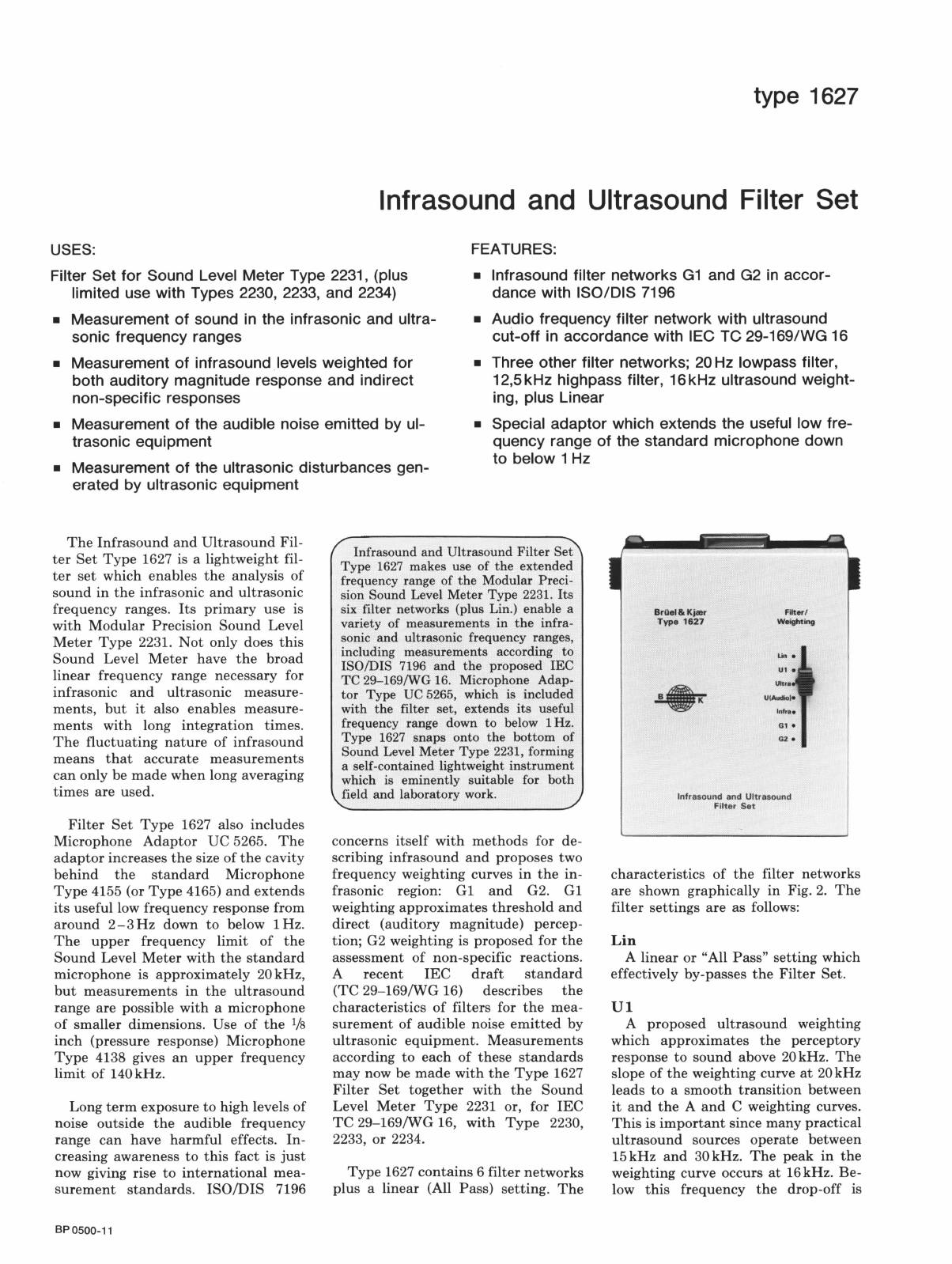
Infrasound
and
Ultrasound Filter
Set
Type
1627 makes use
of
the
extended
frequency range
of
the
Modular Preci-
sion Sound Level
Meter
Type
2231.
Its
six filter networks (plus Lin.) enable a
variety of measurements in
the
infra-
sonic
and
ultrasonic frequency ranges,
including measurements according
to
ISO/DIS 7196
and
the
proposed IEC
TC
29
-169/WG 16. Microphone Adap-
tor
Type
UC 5265, which is included
with
the
filter set, extends
its
useful
frequency range down
to
below
1Hz.
Type 1627 snaps onto
the
bottom
of
Sound Level
Meter
Type
2231, forming
a self-contained lightweight
instrument
which is eminently suitable for
both
field
and
laboratory work.
concerns
itself
with
methods
for de-
scribing
infrasound
and
proposes two
frequency weighting curves
in
the
in-
frasonic region: G1
and
G2. G1
weighting
approximates
threshold
and
direct
(auditory
magnitude)
percep-
tion; G2 weighting is
proposed
for
the
assessment
of
non-specific reactions.
A
recent
IEC
draft
standard
(TC
29-169/WG
16) describes
the
characteristics
of
filters for
the
mea-
surement
of
audible
noise
emitted
by
ultrasonic
equipment.
Measurements
according
to
each
of
these
standards
may
now be
made
with
the
Type
1627
Filter
Set
together
with
the
Sound
Level
Meter
Type
2231 or, for
IEC
TC
29-169/WG
16,
with
Type
2230,
2233,
or
2234.
Type
1627
contains
6 filter
networks
plus
a linear (All
Pass)
setting.
The
BrGel&
Kjaer
Type
1627
FiltM/
Weightiog
lnfre•
Q1.
G2 •
lnfrasound and Ultrasound
filter
Set
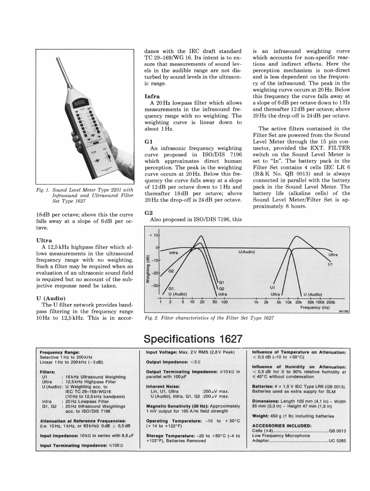
characteristics
of
the
filter networks
are
shown graphically in Fig.
2.
The
filter
settings
are
as follows:
Lin
A
linear
or "All
Pass"
setting which
effectively by-passes
the
Filter
Set.
Ul
A
proposed
ultrasound
weighting
which
approximates
the
perceptory
response
to
sound
above
20kHz.
The
slope
of
the
weighting curve
at
20kHz
leads
to
a
smooth
transition
between
it
and
the
A
and
C weighting curves.
This
is
important
since
many
practical
ultrasound
sources
operate
between
15kHz
and
30kHz.
The
peak
in
the
weighting curve occurs
at
16kHz.
Be-
low
this
frequency
the
drop-off is