Safelab AIRONE FC 750 User manual

DOCUMENT NO: M40 ISSUE NO: 3 ISSUE DATE: 11/07/18
INSTRUCTION MANUAL
AIRONE FC 750
Filtration Fume Cupboard with
Filter Saturation Alarm
SAFELAB SYSTEMS
Airone Building ● 8 Beaufighter Road ● Weston-Super-Mare ● BS24 8EE
Telephone: 01934 421340 Fax: 01934 641569 E-mail: Safelab@safelab.co.uk
WWW.SAFELAB.CO.UK

DOCUMENT NO: M40 ISSUE NO: 3 ISSUE DATE: 11/07/18
2
Contents
Page 2 Contents.
Page 3 Foreword.
Page 4 Principles of Operation.
Page 5 Installation and Assembly Instructions.
Page 6 Installation & Assembly Instructions (continued).
Page 7 Specification.
Page 8 Specification Diagram.
Page 9 Operating Instructions.
Page 10 Operating Instructions (continued).
Page 11 Wiring Diagram.
Page 12 Calibration.
Page 13 Maintenance and Performance Monitoring.
Page 14 Maintenance and Performance Monitoring (continued).
Page 15 Maintenance and Performance Monitoring (continued).
Page 16 Cleaning.
Page 17 Pre-Filter Replacement.
Page 18 Main Filter Replacement.
Page 19 Spare Parts & Troubleshooting.
Page 20 E.C. Declaration of Conformity.

DOCUMENT NO: M40 ISSUE NO: 3 ISSUE DATE: 11/07/18
3
FOREWORD
This manual has been prepared to give guidance in the use of the Airone FC750 filtered
fume cupboard, and to ensure its optimum operation.
It is recommended that service and maintenance operations should only be undertaken
by SAFELAB Service Engineers or their authorised agents.
Details of Service Contracts, along with information on these and other products is
available on request from:
SAFELAB SYSTEMS LTD
Airone Building
8 Beaufighter Road
Weston-Super-Mare
BS24 8EE
Telephone - 01934 421340
Fax - 01934 641569
Website: - http://www.safelab.co.uk
NOTE:
This Airone FC750 Filtration Fume Cupboard requires annual service and
inspection under the requirements of COSHH regulation 9 by a suitably qualified
engineer.

DOCUMENT NO: M40 ISSUE NO: 3 ISSUE DATE: 11/07/18
4
PRINCIPLES OF OPERATION
Air is drawn into the cupboard at the working aperture Abelow the hinged clear acrylic
front window, at a velocity high enough to ensure entrainment of any fumes/odours given
off by the processes carried out within the cupboard.
The fumes from within the cupboard are drawn either upwards as in the case of lighter
than air fumes B to the extract slot D, or drawn across the work surface to the secondary
extract slot Ecreated by the back baffle, as in the case of heavier than air
fumes/particulates* C.
The combination of extract slots Dand Eensure that all fumes/particulates* are carried
by the moving body of air to the pre-filter Fand main filter G to be absorbed before being
expelled by the exhaust fan Has clean air J
The fan H, which is mounted above the main filter exerts a negative pressure on the
internal space within the cupboard. This in turn pulls external air into the cabinet through
the working aperture Aand keeps a constant circulation of pre-filtered clean air passing
through the cupboard whilst ensuring that fumes/particulates* are trapped and adsorbed
by the main filter.
*dependent on main filter type fitted.

DOCUMENT NO: M40 ISSUE NO: 3 ISSUE DATE: 11/07/18
5
INSTALLATION AND ASSEMBLY INSTRUCTIONS
Contents of Packaging (as standard):
-Pre-filter (fitted). - Operational manual.
-Main filter . - Quality Pass.
-Allen key. - Service and Maintenance Letter.
-Mains power lead. - Conformity certificates.
-Safety Log Book. - Warranty form.
Your Airone FC750 fume cupboard should be assembled and sited by specialists using
the correct handling equipment. Please contact Safelab systems for assistance in this
matter.
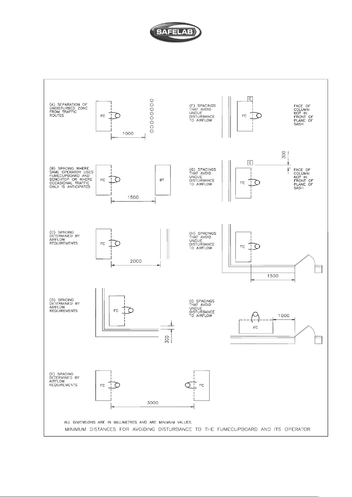
Space for free air circulation must be provided around the Airone FC750 Filtration Fume
Cupboard (see page 6 for a guide to siting the cupboard).
FILTER INSTALLATION (SEE ALSO SPECIFICATION DIAGRAM ON PAGE 8):
1. Ensure cupboard is switched off. Remove the outer front fascia panel by removing
the four Allen screws.
2. Remove the two Allen screws securing the light. Lift the light assembly clear, and
unplug it if necessary.
3. Unpack the main filter and prepare suitable equipment for its safe handling and
installation.
Before lifting the main filter please note that a size B filter weighs approx.
15kg, and may require two people to safely handle it.
Slide the filter gasket side down between the guides in the filter chamber (if using
HEPA/carbon filter, the HEPA is the lower filter, unless the unit is sited in a clean
room, in which case the HEPA filter will be the upper one).
Use the thumbscrews on the filter/fan plenum to evenly clamp the filter in
position.
4. Fill in the date on the filter identification label and stick it to the front of the filter,
ensuring it will be clearly visible through the viewing window on the cover panel.
5. Replace both the light unit and front cover panel and retaining screws, ensuring
the lighting plug is reconnected.
6. Following this procedure, it is recommended that the filter monitoring procedure
detailed in the Operational Safety Manual is performed. This ensures correct
seating of the filter within the cabinet.
Written records of filter monitoring are a legal requirement under COSHH.
7. Connect to the power supply and the cabinet is ready for commissioning.
See Calibration instructions on page 12.

DOCUMENT NO: M40 ISSUE NO: 3 ISSUE DATE: 11/07/18
6
INSTALLATION AND ASSEMBLY INSTRUCTIONS (CONTINUED)
GUIDE TO POSITIONING LOCATIONS FOR THE AIRONE R FUME CUPBOARD

DOCUMENT NO: M40 ISSUE NO: 3 ISSUE DATE: 11/07/18
7
SPECIFICATION
Definition: The SAFELAB Airone FC750 Filtration Fume Cupboards are
designed for the protection of operatorsfrom gaseous or particulates
contaminants produced within the unit.
Application: Wherever the operator and the environment need to be protected
from gaseous phase or particulate contaminants.
Construction: Aluminium extrusions and mild steel, painted in epoxy powder coat,
Light Grey RAL-7035 and White RAL-9016. The sides of the fume
enclosure are laminated safety glass, and white compact laminate.
The fixed upper section and hinged lower section front window is
made from clear acrylic.
The work tray is white polypropylene as standard.
Pre-filter/s: Size B –1 pre-filter.
Filter Housing: Located above the fume cupboard. This contains the main filter and
exhaust fan.
Low Airflow Light: Red, gives a visual indication of a low airflow condition or when the
pre-filter or main filter needs changing. Located on the top RH side
cabinet.
ON/OFF Switch: Illuminated green, and located on the top RH side of the cabinet
below the red low airflow light.
Supply: 230 V 50Hz –1.0A
Lighting: Fluorescent Lamp - 20 watts
Performance: The average inflow at the working aperture is 0.4 m/s.
The working aperture is 200mm high.
Main Filters: Size ‘B’ to customer spec. 1 Filter
Safelab Systems Ltd offer a wide variety of filter types for different
applications, please consult your Operational Safety Log Book.
Weight 44 Kg.
Dimensions: 750mm x 600mm x 1030mm (W x D x H)

DOCUMENT NO: M40 ISSUE NO: 3 ISSUE DATE: 11/07/18
8
SPECIFICATION DIAGRAM
1) Fascia panel.
2) Filter viewing window.
3) Illuminated ON/OFF switch (green).
4) Low airflow warning light (red).
5) Hinged acrylic front window.
6) Exhaust fan.
7) Plenum.
8) Main filter/s.
9) Rear baffles.
10) Fluorescent light.
11) Work tray.
12) Pre-filter.
13) Mains lead with moulded plug.
14) Saturation Alarm.

DOCUMENT NO: M40 ISSUE NO: 3 ISSUE DATE: 11/07/18
9
OPERATING INSTRUCTIONS
(ENSURE THE UNIT IS PLUGGED IN TO THE MAINS ELECTRICAL SUPPLY)
1. Before switching on the unit, check that the main filter is fitted (the filter
identification label will be visible through the filter viewing window on the upper
fascia panel.
2. Switch on at the mains socket and at the green ON/OFF switch on the cupboard
and allow it to run for approximately 10 minutes prior to use.
3. Always use appropriate PPE (personal protection equipment) when using the
Airone FC750 Fume Cupboard.
4. Assess the potential hazard of the intended procedure before commencing work.
The hazard level can be reduced by:
Working with a reduced height of sash opening.
Using reduced quantities of substances involved.
Lowering reaction rates where acceptable.
5. When working in the cupboard, ensure that the hinged acrylic front window is in
the closed position, in order to achieve containment at 0.4M/sec and always keep
closed when the fume cupboard is not in use.
6. If using Bunsen burners, place them at least 20cm from the front sash, sides or
rear baffle.
7. For access to the inside of the fume cupboard for loading apparatus or cleaning,
the hinged lower front acrylic panel, can be fully open and will be held in position
by the two black detent hinges.
NOTE
The hinges will only hold the lower front panel in
the fully open position, when opening make sure
that they click into the fully open position.
!

DOCUMENT NO: M40 ISSUE NO: 3 ISSUE DATE: 11/07/18
10
OPERATING INSTRUCTIONS
(CONTINUED)
8. Try to place everything required for your process inside the fume cupboard prior
to starting any operation. This will reduce the amount of arm movements into and
out of the fume cupboard and hence reduce possibility of breakout (fume escape).
9. Position apparatus inside the fume cupboard so that disturbance to airflow at the
sash opening is minimised.
10. After use follow the correct procedure for disposal of any residues and leave the
fume cupboard in a safe state for further use by others.
11. Before switching off the cabinet after use, allow it to run for a further 5 to 10 minutes
to make sure all hazardous vapours or gasses have cleared, and check that any
bottle are capped or stoppered and no material has been left on the necks or
pooled around the bases.
Good housekeeping is essential to prolong carbon filter life.
FILTER SATURATION ALARM
This unit is fitted with a filter saturation alarm:–
In normal operation, the arrows will be lit with green LEDs. If these turn red and the
audible alarm sounds, it will indicate that the filter is potentially saturated or a
breakthrough has occurred.

DOCUMENT NO: M40 ISSUE NO: 3 ISSUE DATE: 11/07/18
11
WIRING DIAGRAM

DOCUMENT NO: M40 ISSUE NO: 3 ISSUE DATE: 11/07/18
12
CALIBRATION
(SHOULD ONLY BE UNDERTAKEN BY A SUITABLY QUALIFIED PERSON)
1. Remove the outer front fascia panel by removing the four Allen screws.
2. Open the hinged acrylic front window.
3. Hinge down the upper baffle by unscrewing and removing the two thumbscrews at
the front.
4. Switch on the fume cupboard and cover approximately two thirds of the pre-filter
area at the top inside of the enclosure with a suitable piece of paper or card.
5. If the red warning light comeson, rotate pressure switch adjuster screw(see photo)
anticlockwise until it goes out, then slowly rotate it clockwise until the red warning
light just comes on.
If the red waning light doesn’t come on, rotate the adjuster screw clockwise until
the light just comes on.
6. Remove paper or card and check that the light goes out. Repeat steps 4 and 5
until this is achieved.
7. Switch off the fume cupboard and remove the paper/card covering the pre-filter.
8. Raise the hinged baffle, refit the thumbscrews, and fold down the front window.
9. Refit the front fascia panel.

DOCUMENT NO: M40 ISSUE NO: 3 ISSUE DATE: 11/07/18
13
MAINTAINANCE AND PERFORMANCE MONITORING:
Your AironeFC750 Fume Cupboardshould have an annualservice by a suitably qualified person,
to maintain it’s optimal working condition and reduce the possibility of hazard to the operator.
We recommend that a service programme be arranged with Safelab Systems ltd.
Regular maintenance by our qualified personnel will ensure safe running of your
equipment and also ensure that you meet your requirements under COSHH regulation 9.
The minimum requirement to comply with COSHH Regulations is that a routine service and
inspection is carried out at least once every 14 months (including face velocities and filter
efficiencies), and a written record kept of the results. Tables printed on back pages of the
Operational Safety Log-Book are suitable for keeping these records.
Refer to page 14 for face velocity and filter checking procedures.
It is also recommended that the pre-filter be replaced a minimum of once every 3 months.
Safelab Systems offer Service Contracts for regular filter-monitoring and servicing of all AIRONE
Filtration Fume Cupboards. Please contact our Service Department for details:
Phone - 01934 421340
Fax - 01934 641569
Safelab Systems recommend that a simple air sampling test be carried out once a week at eye
and mouth level and/or at the outflow port of the AIRONE Fume Cupboard utilising an appropriate
GASTEC Chemical Detector Tube (available from Safelab Systems). Record result in the
Operational Safety Log-Book.
Information for users for Easy Do-It-Yourself filter-monitoring checks:
Equipment Needed:
A calibrated vane anemometer with a diameter of 100mm and the facility to average readings
over a period of 10 seconds.
Unidirectional Hot-wire Anemometers are also available with the facility of averaging readings.
Refer to Building Bulletin # 88 of the DfEE (rev. of Design Note #29)
GASTEC Volumetric Gas-Detection kit consisting of a disposable tube used with a volumetric
detector hand pump that draws a measured volume of air through the tube. The length of colour
change in the tube indicates the concentration of the gas tested. SAFELAB SYSTEMS supply a
suitable model:
GASTEC Volumetric Detector Pump (Safelab code SRV604).
Additionally packs of disposable tubes will be required.
Pack of 10 Sulphur Dioxide Tubes, 1 pack of 10 Trichloroethylene. Tubes.
Refer to Operational Safety Log-Book and Chemical Listing for correct selection from over 500
different GASTEC chemical detector tubes available for measuring ppm concentration levels of
over 800 compounds in gaseous phase.

DOCUMENT NO: M40 ISSUE NO: 3 ISSUE DATE: 11/07/18
14
MAINTAINANCE AND PERFORMANCE MONITORING (CONTINUED):
INSTRUCTIONS FOR FACE VELOCITY MEASUREMENTS
(Record results on record form - page 15 )
PROCEDURE:
Imagine the face of the fume cupboard divided into nine
cells.
Stand as far as practicable from the fume cupboard with the
sensing head in the plane of the sash and take airflow
readings at approximately the centres of each of the nine
cells.
Record for each cell the approximate average reading over a period of at least ten
seconds, applying any corrections from the air flow meter calibration chart.
Look at the table and repeat any reading which seems to be very different from the
general pattern. Record the average of this and the previous reading.
CALCULATION:
Minimum face velocity -
Record which of a,b,c,d,e,f,g,h,i, is the smallest, i.e.: the minimum face velocity.
VARIATION:
Check for variation as follows :
Add together the values a,b,c,d,e,f,g,h,i and divide by 9 to get the average.
Find the biggest and smallest of a,b,c,d,e,f,g,h,i.
The upper percentage variation is the biggest minus the average, divided by the
average and multiplied by 100.
The lower percentage variation is the average minus the smallest, divided by the average
and multiplied by 100. Each of these should be below 30%.

DOCUMENT NO: M40 ISSUE NO: 3 ISSUE DATE: 11/07/18
15
MAINTENANCE AND PERFORMANCE MONITORING (CONTINUED):
AIRONE FC750 EXAMINATION RECORD
Site:.....................................................................
..............................................................…………
Air flow meter used:.........................................……
…………………………………………………………...
Date
of
Check
Readings in each of the cells as
above.
Average
( m/s )
Pre Filters
Clean?
Any deterioration or
damage observed.
Fail if face velocity
Initials
of
Tester
a
b
c
d
e
f
g
h
i
Yes/No
< 0 . 3 m / s
If a drop of 10% is found then the cause of the problem should be cleared. (Check Pre-filters)
If the minimum face velocity is below 0.3 m / s then airflow in the fume cupboard is inadequate.

DOCUMENT NO: M40 ISSUE NO: 3 ISSUE DATE: 11/07/18
16
MAINTAINANCE AND PERFORMANCE MONITORING (CONTINUED):
INSTRUCTIONS FOR FILTER SATURATION TESTING.
Regular filter checks and monitoring (once a week is recommended) to test quality of the
air breathed in by operators and filtration efficiency. Filter challenge tests can be carried
out during routine Service and Maintenance procedures once every 6 months as
described in the Operational Safety Log Book.
The recommended procedure for testing the efficiency of the system requires a GASTEC
Volumetric Detector Pump and Gastec Chemical Detector Tubes. Test the quality of air
by sampling at eye and mouth level at regular intervals once a week with Gastec tubes
calibrated for the particular compound in concentrations below its respective OEL
(Occupational Exposure Limit) MEL (Maximum Exposure Limit) or OES (Occupational
Exposure Standard (or MAK in Germany and/or TLV in the USA).
Please refer to the Chemical Listing, Adsorption Index and Gastec Detection Guide
published in our Operational Safety Log-Book.
CLEANING
The materials used to construct the Airone FC750 Fume Cupboard have been selected
to give maximum durability and a long life. It is beneficial however to regularly clean and
decontaminate the internal and external surfaces.
It is recommended that the cabinet is switched on during any cleaning procedure and that
suitable protective clothing (face-mask, gloves and safety glasses) is worn.
All surfaces should be cleaned with a mild detergent solution then finished off with a damp
cloth and wiped dry.
If required, the rear/upper baffles can be removed for cleaning. It is recommended that
two people undertake this operation.
Remove the upper screws from the rear baffle, then undo and remove the thumbscrews
supporting the front of the upper baffle and allow in it fold down flat against the rear baffle.
Carefully remove the remaining bottom two screws holding the rear baffle whilst
supporting it.

DOCUMENT NO: M40 ISSUE NO: 3 ISSUE DATE: 11/07/18
17
FILTER REPLACEMENT
DURING THE PRE-FILTER AND MAIN FILTER REPLACEMENT PROCEDURE, SUITABLE
PROTECTIVE CLOTHING (FACE-MASK, GLOVES AND SAFETY GLASSES) MUST BE WORN
PRE-FILTER REPLACEMENT
(SAFELAB RECOMMENDS THAT THE PRE-FILTER IS REPLACED EVERY THREE MONTHS)
1. With the cabinet switched on, raise the hinged front window.
2. Measure and take note of the distance from the front edge of the upper baffle to
the inside top of the fume cupboard and remove the thumbscrews supporting the
front of the upper baffle and allow in it fold down flat against the rear baffle.
3. Undo and remove the thumbscrews retaining the pre-filter clamp frame a little and
remove the pre-filter by folding the front edge away from you so that it is folded
in half, withdraw it, then place and seal it directly into a plastic bag for disposal.
4. Locate the new pre-filter on the clamp frame, raise into position, and replace and
tighten the retaining thumbscrews.
5. Raise the upper baffle and refit the thumbscrews. Adjust to give the same distance
from the inside top as before.
6. Lower the front window.

DOCUMENT NO: M40 ISSUE NO: 3 ISSUE DATE: 11/07/18
18
FILTER REPLACEMENT (CONTINUED)
DURING THE PRE-FILTER AND MAIN FILTER REPLACEMENT PROCEDURE, SUITABLE
PROTECTIVE CLOTHING (FACE-MASK, GLOVES AND SAFETY GLASSES) MUST BE WORN
MAIN FILTER/S REPLACEMENT
(SAFELAB RECOMMENDS THAT THE MAIN FILTER IS REPLACED EVERY FIVE YEARS
DEPENDING ON USE AND APPLICATION)
1. Switch off the cabinet and disconnect it from the mains electricity supply.
2. Remove the front fascia panel by removing the four Allen screws.
3. Remove the two Allen screws securing the light. Lift the light assembly clear, and
unplug it if necessary.
4. Check that the replacement Safelab carbon filter is correctly selected (consult
Safelab Ltd by phone, fax or e-mail for assistance).
5. Unscrew the four knurled knobs inside the main filter housing that clamp the fan
and plenum assembly on top of the filter. Four springs lift the assembly clear of
the main filter as these are released.
6. Unpack the Main filter and prepare suitable equipment for its safe handling.
Place the filter gasket side upwards on a clean flat surface (Retain the packaging
for disposing of the old filter).
7. Before removing the main filter, please note that a size B filter weighs
approx. 15kg, and may require two people to safely handle it.
Firmly grip each side of the main filter, push up to break the seal, and withdraw
the filter.
8. With the gasket side downwards, slide the new filter into place between the
guides in the main filter housing ensuring that it’s located fully to the back stop
and evenly retighten the knurled knobs to clamp the filter in position.
Good filter seating is essential for effective filtration.
9. Fill in the date on the filter identification label and stick it to the front of the new
filter, ensuring it will be clearly visible through the viewing window on the cover
panel.
10. Replace both the light unit and front cover panel and retaining screws, ensuring
the lighting plug is reconnected.
11. Reconnect to the mains electricity supply and switch on the cabinet.
12. Enter details of main filter/s change in the safety Log Book.
13. Following this procedure, it is recommended that the filter monitoring procedure
detailed in the Operational Safety Manual is performed. This ensures correct
seating of the filter within the cabinet.
Written records of filter monitoring are a legal requirement under COSHH.

DOCUMENT NO: M40 ISSUE NO: 3 ISSUE DATE: 11/07/18
19
SPARE-PARTS
Main filter/s (to customer spec.): B size filter
Pre-filters: Part No. 111092 (supplied as pack of 12)
Mains lead: Part No. 050201
Fan: Part No. 060250
Red Neon Light: Part No. 050643
On/Off switch: Part No. 050245
Fluorescent light Part No.050520
Hinge Part No.130407
TROUBLESHOOTING
1. What if I can smell the vapours or gases being used in the procedure?
Filters have a high efficiency but, because the nose is very sensitive, the residual
gases passing through the filter may sometimes be smelt, even though their level
is not hazardous. If the gases are causing distress, the operation should be
finished and the degree of filter saturation monitored.
2. What if I can smell the vapours or gases being used in the procedure,
but I have checked the filter performance and it is satisfactory ?
Check siting of the cabinet to ensure that nothing is being allowed to escape out
through the sash. Fume containment is easily impaired by draughts from windows,
doors or fan heaters and air vents.
3. What if there is a release that the filters of the Airone FC750 cannot contain?
If the initial chemical hazard analysis or risk assessment (under COSHH) has been
carried out correctly resulting in correct selection of appropriate types of carbon
filters followed by weekly air sampling and filter monitoring checks this is unlikely
to occur. In case it does happen, due to accidental release of gas or vapour or an
unexpected spillage, then leave the fan running and evacuate the area. Subject to
the hazard assessment and local considerations, it may be that personnel with
breathing apparatus would have to return to open windows and ensure that all
hazardous vapours or gases had been dispersed.
It is recommended that replacement carbon filter/s are kept available at short
notice for such an event.
WARNING:
If a spill exceeds the capabilities of the Airone FC750, it is likely to exceed the capabilities
of carbon filtration facemasks. This means that only an air or oxygen cylinder based
breathing apparatus could provide adequate protection.

DOCUMENT NO: M40 ISSUE NO: 3 ISSUE DATE: 11/07/18
20
Table of contents
Popular Water Filtration System manuals by other brands

Ultrafilter
Ultrafilter P-EG manual

Donaldson
Donaldson AFS-BH430-IBF-ICA instructions

Whirlpool
Whirlpool WHAPSRO Installation and operation manual

BWT
BWT AQA drink Magnesium Mineralized Water Protect... Installation and operating instructions

Pentair
Pentair EVERPURE PRO Installation and operating instructions

Donaldson Torit
Donaldson Torit Dalamatic Cased DLMC 1/2/15 Installation and operation manual