Brüel & Kjaer Vibro VIBROCONTROL 950 User manual

Keep it accessible for future reference.
VIBROCONTROL 950/960
Short Instruction
Single channel vibration monitoring units

Page 2 of 8 █ © Brüel & Kjaer Vibro ●January 2018 ● C106833.002 / V01
Technical alterations reserved!
EN
Copyright © 2017 Brüel & Kjaer Vibro GmbH
All rights to this technical documentation remain reserved.
Any corporeal or incorporeal reproduction or dissemination of this technical documentation or making this
document available to the public without prior written approval from Brüel & Kjaer Vibro GmbH shall be
prohibited. This also applies to parts of this technical documentation.
Brüel & Kjaer Vibro GmbH
Leydheckerstrasse 10
64293 Darmstadt
Germany
Phone: +49 6151 428-0
Fax: +49 6151 428-1000
E-Mail: info@bkvibro.com
Hotline:
Phone: +49 6151 428-1400
E-Mail: support@bkvibro.com
Content
1Applications 3
2VIBROCONTROL 900 Series Types 3
2.1 VIBROCONTROL 950 Accelerometers (CCS) 3
2.2 VIBROCONTROL 960 Velocity Sensors 3
3Hints for safe operation of VIBROCONTROL 950/960 4
4Setup the VIBROCONTROL 950/960 5
4.1 RS232 interface 5
4.2 RS485 interface 5
4.3 The Compact Setup Software 6
NOTE!
This symbol provides general and useful information for using the product.

© Brüel & Kjaer Vibro │Short Instruction VC-950/960 Applications
EN
© Brüel & Kjaer Vibro ●January 2018 ● C106833.002 / V01 ●█Page 3 of 8
Technical alterations reserved
1 Applications
The VIBROCONTROL 950/960 Vibration Monitor is a maintenance free device situated mounted in a
DIN rail enclosure. It can be used to monitor vibration parameters in applications with machines like
pumps, blowers, ventilators, decanters, separators, centrifuges, mills and milling equipment.
The VIBROCONTROL 950/960 Vibration Monitor continuously keeps track of the vibration level of a
machine at the point where the external acceleration sensor is fixed to that machine.
VIBROCONTROL 950/960 vibration monitors have different hardware depending on the type
of sensor connected to the unit. It is NOT possible to connect a proximity or velocity sensor to
a VIBROCONTROL 950/960 designed for use with an acceleration sensor, and vice-versa.
The VIBROCONTROL 950/960 Vibration Monitors have a RS232/RS485 serial interface which can be
used to read-out the vibration level and status information. The PC-program used for this is called
Compact Commander Software.
2 VIBROCONTROL 900 Series Types
2.1 VIBROCONTROL 950 Accelerometers (CCS)
Connecting with acceleration sensors (CCS)
2.2 VIBROCONTROL 960 Velocity Sensors
Connecting with velocity sensors

Page 4 of 8 █ © Brüel & Kjaer Vibro ●January 2018 ● C106833.002 / V01
Technical alterations reserved!
EN
3 Hints for safe operation of VIBROCONTROL 950/960
General:
Please carefully read the operating instructions prior to set-up of the device. Make sure that your
VIBROCONTROL 950/960 device is suitable for your application without any restrictions.
Improper use:
Any improper or non-intended use may lead to malfunctions of the VIBROCONTROL 950/960 device
or to unwanted effects in your application. If the VIBROCONTROL 9x0 is used in a way not described
in the relevant user manuals, function and protection may be impaired and serious personal damage,
death or serious, irreversible injuries may result.
EU-directives:
All versions of the VIBROCONTROL 950/960 device conform to the relevant regulations and EC
directives.
Installation and operation:
Installation, electrical connection, set-up, operation and maintenance of your VIBROCONTROL
950/960 device(s) must only be carried out by qualified/trained personnel (electrician) authorised by
the machine operator in accordance with local- and national regulations for the installation of electrical
equipment.
Changing the setup parameters:
Before applying a new set of setup parameters to the VIBROCONTROL 950/960 device, please make
sure that doing so cannot cause any damage to persons and/or machinery.
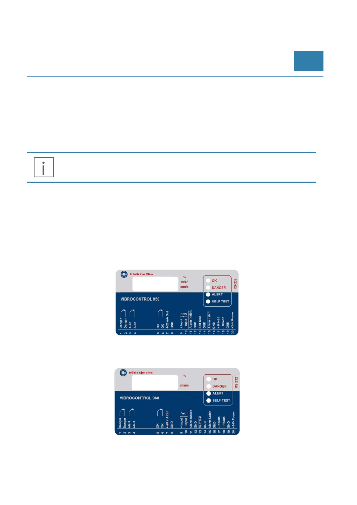
Connecting the sensor(s):
Please make sure to meet the safe extra-low voltage (SELV) criteria when any sensors are connected
to the VIBROCONTROL 950/960 device so that no dangerous contact voltages are applied to the
sensor and/or transferred to the device. The sensor and the power supply of the VIBROCONTROL
950/960 device are not galvanic isolated.
Sensor cable mounting:
To prevent negative effects on the functioning of the VIBROCONTROL 950/960 device caused by
noise voltages, please lay shielded sensor cables and load cables separately.
Ingress protection (IP):
The VIBROCONTROL 950/960 is ranked as IP20. The VIBROCONTROL 950/960 device must be
mounted in a control cabinet with an ingress protection of at least IP54. The control cabinet should be
installed in accordance with local- and national rules and regulations.
Mounting:
Mount the VIBROCONTROL 950/960 device on a 35 mm DIN rail inside the control cabinet. Mount the
device vertically but make sure to leave enough space between the unit and the top and/or bottom of
the control cabinet. Only this way the air circulation will be sufficient to avoid excessive heating of the
device.
Connecting to a power supply:
The VIBROCONTROL 950/960 device has a voltage tolerance of +24 VDC ±5 %
Before connecting the VIBROCONTROL 950/960 device to a +24 VDC supply voltage, please make
sure that all terminal blocks are completely inserted.
The external +24 VDC supply voltage must be generated and supplied according to the SELV
requirements.
Protect the +24 VDC supply voltage externally with max. 2A. The ground (GND) of the DC supply is
directly connected with the ground (GND) of the sensor supply, if any. The SELV criteria must
therefore be met for the DC supply (safety extra-low voltage, circuit electrically isolated from other
circuits, not grounded). If the DC circuit is to be grounded (e.g. due to national regulations), the

© Brüel & Kjaer Vibro │Short Instruction VC-950/960 Setup the VIBROCONTROL 950/960
EN
© Brüel & Kjaer Vibro ●January 2018 ● C106833.002 / V01 ●█Page 5 of 8
Technical alterations reserved
protective-extra-low-voltage (PELV) criteria must be adhered to (SELV with circuit galvanic isolated
from other circuits).
Maintenance:
If used correctly no maintenance and repair measures are necessary. Only the manufacturer is
allowed to repair the unit.
4 Setup the VIBROCONTROL 950/960
The VIBROCONTROL 950/960 Vibration Monitor is provided with a RS232 and a RS485 interface,
which allows the user to change many of the setup parameters. The RS232/RS485 interface can also
be used to read out a number of registers inside the vibration monitor with status information or the
actual vibration level.
The PC program used for this purpose is called Compact Setup Software.
The VIBROCONTROL 950/960 Vibration Monitor is delivered with a pre-configured setup. The
Compact Setup Software will overwrite this setup when it is used to change the changeable
parameters in the device, thus declaring the official factory setup void.
4.1 RS232 interface
To use the RS232 interface, connect a null-modem cable between the VIBROCONTROL 950/960
Vibration Monitor and the COM-port on the computer. The male 9-pin D-sub socket marked “RS232” is
placed at the right side of the VIBROCONTROL 950/960 Vibration Monitor.
Using the RS232 interface overrules the RS485 interface, which will automatically be disabled. To
connect with USB port please use RS232/USB adapter.
4.2 RS485 interface
The VIBROCONTROL 950/960 Vibration Monitor allows “multi-drop”, i.e. up to 255 devices can be
addressed individually in a RS485 chain of devices.
To use the RS485 interface, connect terminal #17 (marked: “+RS485”) and terminal #18 (marked: “–
RS485”) of the VIBROCONTROL 950/960 Vibration Monitor to the RS485 chain of devices using a
shielded cable.
Terminals #1 to #20
RS232 connector
RS485 termination
DIN-rail adaptor
Display

Page 6 of 8 █ © Brüel & Kjaer Vibro ●January 2018 ● C106833.002 / V01
Technical alterations reserved!
EN
The cable must be terminated with a 120 Ωresistor in both ends, i.e. on the PC side and at the last
device on the RS485 chain of devices. The VIBROCONTROL 950/960 Vibration Monitor has a built-in
120 Ωresistor, which can be used for this purpose.
To switch the resistor ON, use the small sliding switch on the right side of the enclosure. A LED behind
terminals #17 and #18 will show green light to indicate that the 120 Ω termination resistor is in place.
The RS485 interface will be disabled as soon as the device senses that the RS232 interface
is used.
Please make sure that you do not add a new device to your FieldBus that has an address
occupied by another device in the chain.
4.3 The Compact Setup Software
To change the set-up parameters of the VIBROCONTROL 950/960 Vibration Monitor and read the
measurement results using a PC, use the Compact Commander Software.
First you have to install the Software; therefore a number of installation windows will guide you through
the installation process:
The Compact Setup Software is supporting Microsoft Windows 7, 8 & 10.
1. Insert the Compact Commander Setup CD in the CD drive.
2. Open the directory for the CD drive e.g. E:\ and open the Compact Commander Setup program:
•Select your language for application and click Next.
•Follow the instruction on the PC.
Be sure to select under "Install OPC
Server" as option "As Standalone"!

© Brüel & Kjaer Vibro │Short Instruction VC-950/960 Setup the VIBROCONTROL 950/960
EN
© Brüel & Kjaer Vibro ●January 2018 ● C106833.002 / V01 ●█Page 7 of 8
Technical alterations reserved
Program Start Icon
To start the program click on the start icon in the menu bar and click on the Compact Setup icon
(Depending on your PC setup, please start the program “Run as administrator”).
Main Menu
Add a device
When using an USB adapter as a connection between VC-9xx series and the Computer, the
interface has to be set up first. Therefore open the device manager on the computer and open
the settings of used port. insert 115200 in the field for bits/s.
•Click on the Add device icon and tick on the option “Search for devices”. Then insert
following information in the drop-down menu:
○Connection Type: RS232
○Com Port: Number of the used port
○Baudrate: 115200
•Confirm with Next.
When the search was successful the main window appears and the selected device including its
configuration is shown under the info register.

Contact
Brüel & Kjaer Vibro GmbH
Leydheckerstrasse 10
64293 Darmstadt
Germany
Phone: +49 6151 428-0
Fax: +49 6151 428-1000
VC-950/960 ● C106833.002 / V01 ●© Brüel & Kjaer Vibro ●Technical alterations reserved!
Editing Device
•Click on the „ Editing Device “ Icon in the Tool bar:
This manual suits for next models
1
Table of contents
Other Brüel & Kjaer Vibro Measuring Instrument manuals
Popular Measuring Instrument manuals by other brands

ELECTRO-OPTICS
ELECTRO-OPTICS KILO2400ABS owner's manual

BERTHOLD TECHNOLOGIES
BERTHOLD TECHNOLOGIES LB 567 user guide

FMC Technologies
FMC Technologies MPU B Series Procedures manual

iwis
iwis CCM-S Series operating instructions

ELECRAFT
ELECRAFT W2 owner's manual

PCB Piezotronics
PCB Piezotronics 608A11/-0112 Installation and operating manual