Brüel & Kjaer Vibro VIBROCONTROL 850 User manual

Keep it accessible for future reference.
VIBROCONTROL 850
Instruction
Single channel vibration monitor

Copyright © 2017 Brüel & Kjaer Vibro GmbH
All rights to this technical documentation remain reserved.
Any corporeal or incorporeal reproduction or dissemination of this technical documentation or making this
document available to the public without prior written approval from Brüel & Kjaer Vibro GmbH shall be
prohibited. This also applies to parts of this technical documentation.
Brüel & Kjaer Vibro GmbH
Leydheckerstrasse 10
64293 Darmstadt
Germany
Phone: +49 6151 428-0
Fax: +49 6151 428-1000
E-Mail: inf[email protected]om
Hotline:
Phone: +49 6151 428-1400
E-Mail: support@bkvibro.com

© Brüel & Kjaer Vibro ●October 2017 ● C106635002 / V01 ●█Page 3 of 20
Technical alterations reserved!
© Brüel & Kjaer Vibro │Instruction VC-850 Content EN
Content
1Applications 4
2Hints for safety operations of VIBROCONTROL 850 4
3Functionality 5
3.1 DIP-switches 6
3.2 How to get access to the set-up DIP-switches 6
3.3 Measuring Parameter (mm/s) 7
3.4 Measuring Range Full Scale 7
3.5 Frequency Bandwidth 7
3.6 Alert Alarm Trigger Level 7
3.7 Alert Alarm Delay Time 8
3.9 Danger Alarm Trigger Level 9
3.10 Danger Alarm Delay Time 9
3.11 Vibration Level During Self-Test 10
3.13 System Failure 11
3.14 Hang Time 11
3.15 Latch Function 11
3.16 Overload 11
3.17 Over range 12
3.18 DC Analogue Output 12
3.19 Alarm Output (relays) 12
3.20 Light Emitting Diodes (LEDs) 13
3.21 Self-Test Function 13
3.22 Sensor Test 13
3.23 Measuring Direction 14
3.24 Reset of Alarms 14
3.25 Inhibit Alarms 14
3.26 Grounding the housing of the device 14
4Mounting of the VIBROCONTROL 850 15
5Cable Connections 16
5.1 Standard Cable Configuration 16
6Technical data 17
7Maintenance 19
8Disposal 19

Page 4 of 20 █ © Brüel & Kjaer Vibro ●October 2017 ● C106635002 / V01
Technical alterations reserved!
EN
WARNING!
This symbol warns of dangerous situations which can result from misuse of the product.
NOTE!
This symbol provides general and useful information for using the product.
1 Applications
The VIBROCONTROL 850 is a maintenance free device and can be used to monitor vibration
parameters in applications with machines like pumps, blowers, ventilators, decanters, separators,
centrifuges, mills and milling equipment.
In case the VIBROCONTROL 850 needs to have removed the lid for change of settings, make
sure that the O-ring is in place and not damaged.
The VIBROCONTROL 850 continuously keeps track of the vibration level of a machine at the point
where it is fixed to that machine.
The vibration parameters are given in true RMS of the vibration signal in mm/s.
The VIBROCONTROL 850 has two alarms, respectively called Alert and Danger, which can be used to
give alarm(s) if the machine vibration level exceeds certain pre-set trigger level(s).
2 Hints for safety operations of VIBROCONTROL 850
General:
Please carefully read the operating instructions prior to set-up of the device. Make sure that your
VIBROCONTROL 850 is suitable for your application without any restrictions.
Improper use:
Any improper or non-intended use may lead to malfunctions of the VIBROCONTROL 850 or to
unwanted effects in your application. If the VIBROCONTROL 850 is used in a way not described in
the relevant user manuals, function and protection may be impaired and serious personal damage,
death or serious, irreversible injuries may result.
EU-directives:
All versions of the VIBROCONTROL 850 conform to the relevant regulations and EC directives.
Installation and operation:
Installation, electrical connection, set-up, operation and maintenance of your VIBROCONTROL
850(s) must only be carried out by qualified/trained personnel (electrician) authorized by the machine
operator in accordance with local- and national regulations for the installation of electrical equipment.
Changing the setup parameters:
Before applying a new set of setup parameters to the VIBROCONTROL 850, please make sure that
doing so cannot cause any damage to persons and/or machinery.

© Brüel & Kjaer Vibro ●October 2017 ● C106635002 / V01 ●█Page 5 of 20
Technical alterations reserved!
© Brüel & Kjaer Vibro │Instruction VC-850 Functionality EN
Maintenance:
If used correctly no maintenance and repair measures are necessary. Only the manufacturer is
allowed to repair the unit. At the end-of-life-cycle, please dispose of the unit in an environmentally
friendly way in accordance with the applicable national regulations.
3 Functionality
The VIBROCONTROL 850 is a vibration monitor device with an internal accelerometer, as well as
conditioning-, alarm-, test-, and output circuitries, all placed in a stainless steel enclosure. The internal
accelerometer sensor has a maximum bandwidth of 10 – 1000 Hz.
The VIBROCONTROL 850 is designed to monitor mechanical vibrations on machines according to
DIN/ISO-10816. In compliance with this standard the machine vibration must be monitored in mm/s
and within a frequency bandwidth of 10 – 1000 Hz.
In the VIBROCONTROL 850 the momentary vibration level is continuously compared with two alarm
trigger levels respectively called Alert and Danger. If an alarm trigger level has been exceeded, the
corresponding alarm relay (respectively Danger Relay and/or Alert Relay) will become activated and
thereby inform the user, e.g. via a connected rotor light, beeper, controller or by directly shutting down
the machine.
The VIBROCONTROL 850 provides a 4-20 mA DC output signal, which at any time expresses the
vibration level relative to the chosen measuring range.
Using DIP-switches that can be accessed – after the lid of the enclosure has been removed – the
customer has the possibility to set a number of parameters.
See paragraph 3.2 how to remove the lid.

Page 6 of 20 █ © Brüel & Kjaer Vibro ●October 2017 ● C106635002 / V01
Technical alterations reserved!
EN
3.1 DIP-switches
There are 8 DIP-switches that are combined in three groups:
•Measurement range (DIP-switches #1 and #2):
There are four possible measurement ranges with different full scale values that can be used
when the VIBROCONTROL 850 is working in “Standard Mode”.
The actual four (4) possible full scale values are set by the factory to default values.
•Mode (DIP-switches #3, #4 and #5):
Under “Mode” the user has the possibility to setup alert and danger alarm trigger level, alert
and danger delay time and the self-test level in standard mode. DIP-switch #6 must be in OFF
position.
Switch position Parameter setting Value range
#3 #4 #5
(0)
(1)
(2)
(3)
(4)
(5)
(6)
(7)
Off
Off
Off
Off
On
On
On
On
Off
Off
On
On
Off
Off
On
On
Off
On
Off
On
Off
On
Off
On
Parameter setting mode inactive
Danger alarm delay time
Danger Alarm trigger level
Not applicable
Alert Alarm trigger level
Analogue output level during Self-Test
Alert Alarm delay time
Not applicable
None
1-100 s
1-100 % of FS
None
1-100 % of FS
1-100 % of FS
1-100 s
None
•Miscellaneous (DIP-switches #6, #7 and #8):
○- DIP-switch #6 not used
○- DIP-switch #7 switches the Self-Test function On or Off (see section 3.20)
○- DIP-switch #8 connects the enclosure to GND (see section 3.25).
3.2 How to get access to the set-up DIP-switches
If the need arises, the customer can change certain setup parameters by means of eight DIP-switches
and two up/down pushbuttons.
In order to have access to the DIP-switches and pushbuttons the customer will have to carry out the
following procedure:
1) Remove the lid, using a coin or a large screwdriver
2) Remove the lid and the sealing O-Ring
Do NOT commence the removal of the lid before the power has been switched off.
In case the VIBROCONTROL 850 needs to have removed the lid for change of settings, make
sure that the O-ring is in place and not damaged.

© Brüel & Kjaer Vibro ●October 2017 ● C106635002 / V01 ●█Page 7 of 20
Technical alterations reserved!
© Brüel & Kjaer Vibro │Instruction VC-850 Functionality EN
3.3 Measuring Parameter (mm/s)
The VIBROCONTROL 850 will be delivered with velocity in mm/s as the default parameter according
to ISO-10816, which is the most common standard related to machine vibration.
3.4 Measuring Range Full Scale
In manual mode the full scale of the measuring range is selectable by the customer using two DIP-
switches (1 & 2) marked Meas. Range Full Scale.
Whenever the VIBROCONTROL 850 is setup to measure velocity in mm/s, the settings of DIP-
switches 1 & 2 will have the following meaning by default 20 mm/s.
#1 #2 Full Scale
(FS) Range Range in
mm/s
(0)
(1)
(2)
(3)
Off
On
Off
On
Off
Off
On
On
FS 1
FS 2
FS 3
FS 4
10
20
50
100
3.5 Frequency Bandwidth
The VIBROCONTROL 850 will be delivered with a frequency bandwidth of 10-1,000 Hz.
3.6 Alert Alarm Trigger Level
The Alert Alarm Trigger Level is the vibration threshold level that must be exceeded for at least the
Alert alarm delay time for the Alert alarm to become activated.
By default the Alert alarm trigger level is set to be 35 % of full scale.
Alternatively the customer can set the Alert alarm trigger level to his/her likings by using the following
procedure:
•Remove the lid that covers the VIBROCONTROL 850.
•Connect a digital multi meter in DC mA mode with a full-scale deflection of at least 20 mA to
the wires “GND” (-) and “4-20 mA Output” (+).
•Set DIP-switches 3, 4 & 5 in position (On – Off – Off)
•If e.g. the Alert alarm trigger level is 50 % the multi meter will show an analogue output of
12.0 mA.
•The analogue output can be changed to any value between 1 % and 100 % of selected full
scale by pushing the buttons up and down at the left and right bottom of the round plate. Each
pushing of the respective button will decrease or increase the Alert alarm trigger level by 0.5 %
of full scale. Stop pushing the buttons when the required Alert alarm trigger level has been
reached. When one of the buttons is held down it will continuously change the Alert alarm
trigger level.
•When finished put the DIP-switches 3, 4 & 5 into the position Off – Off – Off, which will bring
the VIBROCONTROL 850 back into normal monitoring mode with the new settings in place.

Page 8 of 20 █ © Brüel & Kjaer Vibro ●October 2017 ● C106635002 / V01
Technical alterations reserved!
EN
Failing to put the DIP-switches 3, 4 & 5 in Off – Off – Off position after the setting is finished,
will have the consequence that the analogue output will continuously be showing the Alert
alarm trigger level and the vibration guard will therefore NO LONGER react on any alarm
trigger levels, i.e. neither from Alert nor Danger alarms.
3.7 Alert Alarm Delay Time
The Alert Alarm Delay Time is the minimum time the vibration level must exceed the pre-set Alert
alarm trigger level before the alarm gets activated. This is to avoid false alarms in situations where an
allowed short-lived shock (transient) is imposed on the machine. This could be when e.g. a new piece
of raw material is placed in or taken out of the machine.
The Alert alarm delay time is 3 seconds. The customer can set the Alert alarm delay time to the
following procedure:
•Remove the lid that covers the VIBROCONTROL 850.
•Connect a digital multi meter in DC mA mode with a full-scale deflection of at least 20 mA to
the wires “GND” (-) and “4-20 mA Output” (+).
•Set DIP-switches 3, 4 & 5 in position (On – On – Off).
•If e.g. the Alert alarm delay time is 10 seconds the multi meter will show an analogue output of
5.6 mA.
•The Alert alarm delay time can be changed to any value between 0 second and 100 seconds
by pushing the buttons up and down at the left and right bottom of the round plate. 0 second is
4 mA and 100 seconds is 20 mA. Each pushing of the button will decrease or increase the
Alert alarm delay time by half a second. When one of the buttons is held down it will
continuously change the Alert Alarm Delay Time. Stop pushing the buttons when the required
Alert Alarm Delay Time has been reached.
•When finished put the DIP-switches 3, 4 & 5 into the position Off – Off – Off, which will bring
the VIBROCONTROL 850 back into normal monitoring mode with the new settings in place.
Failing to put the DIP-switches 3, 4 & 5 in Off – Off – Off position after the setting is finished,
will have the consequence that the analogue output will continuously be showing the Alert
alarm delay time and the vibration guard will therefore NO LONGER react on any alarm trigger
levels, i.e. neither from Alert nor Danger alarms.

© Brüel & Kjaer Vibro ●October 2017 ● C106635002 / V01 ●█Page 9 of 20
Technical alterations reserved!
© Brüel & Kjaer Vibro │Instruction VC-850 Functionality EN
3.9 Danger Alarm Trigger Level
The Danger Alarm Trigger Level is the vibration level at the analogue output that must be exceeded for
at least the Danger alarm delay time for the Danger alarm to become activated.
By default the Danger alarm trigger level is set to be 55 % of full scale in Band 1.
The customer can set the Danger alarm trigger level by using the following procedure:
•Remove the lid that covers the VIBROCONTROL 850.
•Connect a digital multi meter in DC mA mode with a full-scale deflection of at least 20 mA to
the wires “GND” (-) and “4-20 mA Output” (+).
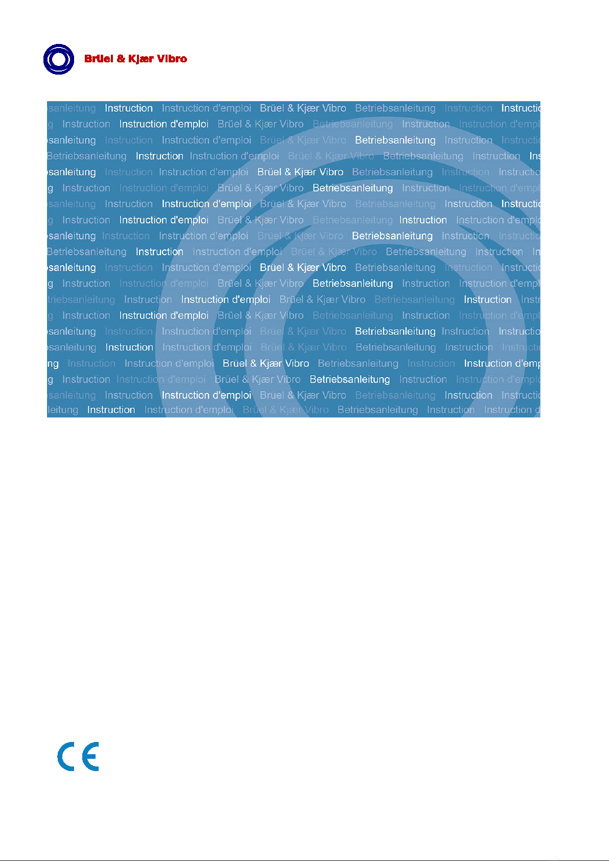
•Set DIP-switches 3, 4 & 5 in position (Off – On – Off)
•The analogue output can be changed to any value between 1 % and 100 % of full scale by
pushing the buttons “On” and “Off” at the left and right bottom of the round plate. Each pushing
of the button will decrease or increase the limit by 0.5 % of full scale. Stop pushing the buttons
when the required Danger alarm trigger level has been reached. When one of the buttons is
held down it will continuously change the Danger alarm trigger level.
•When finished put the DIP-switches 3, 4 & 5 into the position Off – Off – Off, which will bring
the VIBROCONTROL 850 back into normal monitoring mode with the new settings in place.
Failing to put the DIP-switches 3, 4 & 5 in Off – Off – Off position after the setting is finished,
will have the consequence that the analogue output will continuously be showing the Alert
alarm delay time and the vibration guard will therefore NO LONGER react on any alarm trigger
levels, i.e. neither from Alert nor Danger alarms.
3.10 Danger Alarm Delay Time
The Danger Alarm Delay Time is the minimum time the vibration level must exceed the pre-set Danger
alarm trigger level before the alarm gets activated. This is to avoid false alarms in situations where an
allowed short-lived shock (transient) is imposed on the machine. This could be when e.g. a new piece
of raw material is placed in or taken out of the machine.
The Danger alarm delay time is 1 second.
The customer can set the Danger alarm delay time by the following procedure:
•Remove the lid that covers the VIBROCONTROL 850.
•Connect a digital multi meter in DC mA mode with a full-scale deflection of at least 20 mA to
the wires “GND” (-) and “4-20 mA Output” (+).
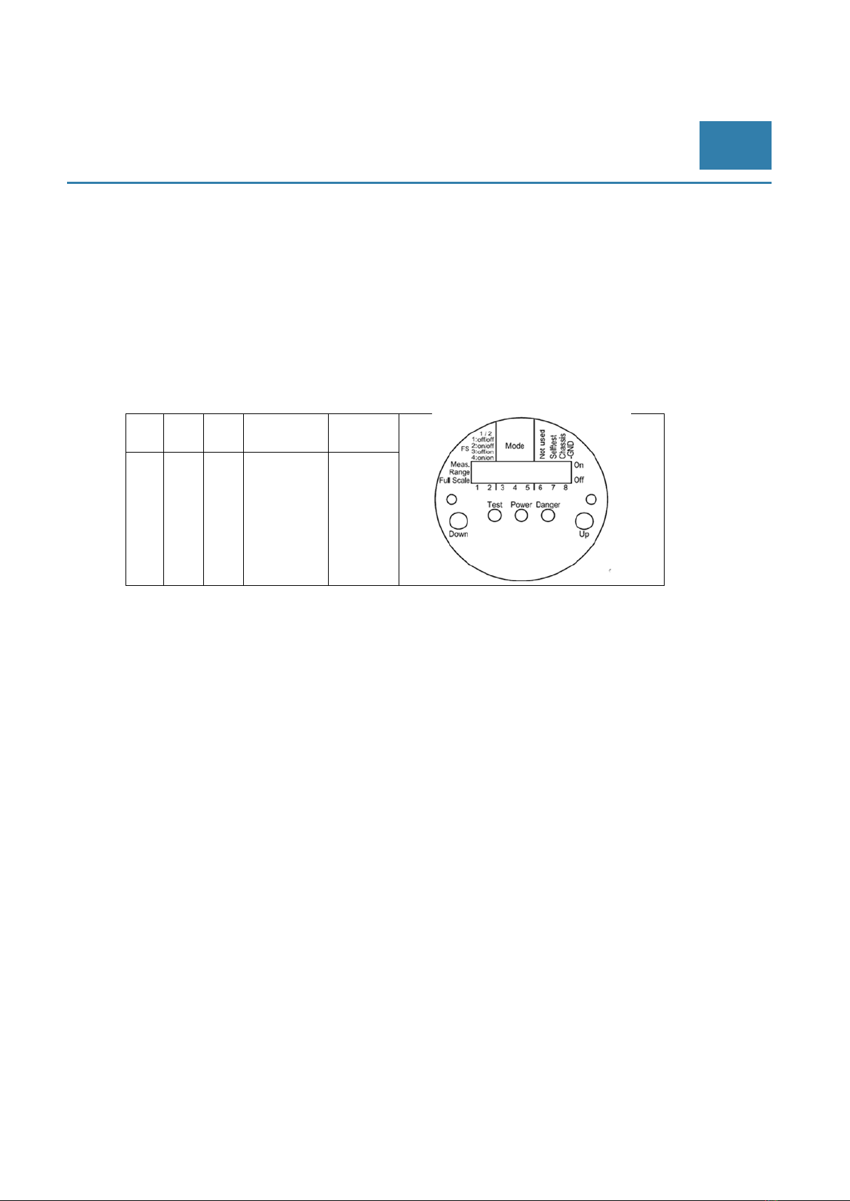
•Set DIP-switches 3, 4 & 5 in position (Off – Off – On).
•The analogue output can be changed to any value between 0 seconds and 100 seconds by
pushing the buttons “On” and “Off” at the left and right bottom of the round plate. 0 seconds is
4 mA and 100 seconds is 20 mA. Each pushing of the button will decrease or increase the
Danger alarm delay time by half a second. When one of the buttons is hold down it will
continuously change the Danger alarm delay time. Stop pushing the buttons when the required
Danger alarm delay time has been reached.
•When finished put the DIP-switches 3, 4 & 5 into the position Off – Off – Off, which will bring
the VIBROCONTROL 850 back into normal monitoring mode with the new settings in place.

Page 10 of 20 █ © Brüel & Kjaer Vibro ●October 2017 ● C106635002 / V01
Technical alterations reserved!
EN
Failing to put the DIP-switches 3, 4 & 5 in Off – Off – Off position after the setting is finished,
will have the consequence that the analogue output will continuously be showing the Alert
alarm delay time and the vibration guard will therefore NO LONGER react on any alarm trigger
levels, i.e. neither from Alert nor Danger alarms.
3.11 Vibration Level During Self-Test
The vibration level, as well as the DC-current at the analogue output is by default pre-set to 102 % (of
full scale) when running a Self-Test, i.e. 20 mA. The analogue output level during Self-Test value can
be set to be more than 100 % (20 mA) to ensure that there will be a minimum of at least 20 mA at the
analogue output whenever the Self-Test is activated.
In order to test the integrity of the VIBROCONTROL 850, it's recommended that the Self-Test is carried
out either manually or automatically (by e.g. a PLC-controller) on a regular basis.
The Self-Test can be activated on the wire input or by DIP-switch.
Failing to put the DIP-switches 3, 4 & 5 in Off – Off – Off position after the setting is finished,
will have the consequence that the analogue output will continuously be showing the Alert
alarm delay time and the vibration guard will therefore NO LONGER react on any alarm trigger
levels, i.e. neither from Alert nor Danger alarms.
Alternatively the customer can set the analogue output level during Self-Test to his/her likings by using
the following procedure:
•Remove the lid that covers the VIBROCONTROL 850.
•Connect a digital multi meter in DC mA mode with a full-scale deflection of at least 20 mA to
the wires “GND” (-) and “4-20 mA Output” (+).
•Set DIP-switches 3, 4 & 5 in position (On – Off – On).
•If e.g. the Self-Test level is 100 % the multi meter will show an analogue output of 20.0 mA.
•The analogue output can be changed to any value between 0 % and 110 % of full scale by
pushing the buttons “Down” and “Up” at the left and right bottom of the round plate. 0 % is 4
mA, 100 % is 20 mA. The maximum is 110 % or 21.6 mA. Each pushing of the button will
decrease or increase the analogue output level during self-test by 1 %. When one of the
buttons is held down it will continuously change the analogue output level for the Self-Test.
Stop pushing the buttons when the required Self-Test output level has been reached.
•When finished put the DIP-switches 3, 4 & 5 into the position Off – Off – Off, which will bring
the VIBROCONTROL 850 back into normal monitoring mode with the new settings in place.
Failing to put the DIP-switches 3, 4 & 5 in Off – Off – Off position after the setting is finished,
will have the consequence that the analogue output will continuously be showing the Alert
alarm delay time and the vibration guard will therefore NO LONGER react on any alarm trigger
levels, i.e. neither from Alert nor Danger alarms.

© Brüel & Kjaer Vibro ●October 2017 ● C106635002 / V01 ●█Page 11 of 20
Technical alterations reserved!
© Brüel & Kjaer Vibro │Instruction VC-850 Functionality EN
3.13 System Failure
The VIBROCONTROL 850 has an internal surveillance system, including a watchdog. This
surveillance system will constantly monitor the correct functioning of the unit. As soon as an internal
fault is detected, such as a transducer bias error, a processor error, or a not-passed self-test, this is
considered to be a very serious situation and a system failure procedure will be activated. In general a
System Failure is non-latched and therefore will end as soon as the error no longer exists.
Whenever a system failure is detected the following actions are taken:
•Danger alarm relay will be activated (break), while the alert alarm is NOT activated.
•The analogue output drops to 0 mA (and NOT 4 mA). Measurable at PLC level.
•The yellow power LED will be blinking (but is only visible if the lid is removed).
Some system failures are latched and can only be removed by either performing a complete
successful Self-Test or by removing the main power from the unit during a few seconds.
3.14 Hang Time
This is the time an Alert or Danger alarm relay will remain activated even though the vibration level has
decreased to below the pre-set trigger level. The hang time for these relays is set to 1 second.
When the Danger Relay act as a system failure output it has no hang time, but it will remain activated
until the system failure condition has ended or reset, e.g. after a complete successful self-test or by
removing the main power from the unit for a few seconds.
3.15 Latch Function
The latch feature of the VIBROCONTROL 850 ensures that the alarm relay(s) stay triggered, even
though the vibration level is reduced to below the alarm trigger level for longer than the hang time.
Applying a GND signal to the “/ Latch alarms” wire can latch the relays.
3.16 Overload
The VIBROCONTROL 850 is provided with an overload detection system that detects the occurrence
of an overload situation, i.e., when the vibration level exceeds the maximum vibration level of the built-
in accelerometers.
The overload detection system has a hang time of approximately 1 second.
The detection of an overload condition generates a system failure (NOK status).
The alert relay is inactive and the danger relay is active (system error).
The DC analogue output will move to 0 mA to indicate the overload condition as a
failure. The “Power LED” is blinking (behind the lid).

Page 12 of 20 █ © Brüel & Kjaer Vibro ●October 2017 ● C106635002 / V01
Technical alterations reserved!
EN
3.17 Over range
The VIBROCONTROL 850 Vibration Monitor is provided with an over range detection system.
The detection of an over range will not generate a system failure (OK failure).
The status of the alarm relays is active.
The DC analogue output will move to 20,5 mA to indicate the over range condition.
3.18 DC Analogue Output
At the “4-20 mA output wire” a DC output current will be available, which is direct proportional to the
vibration level. An output current of 4 mA at the DC output represents a value of 0 mm/s, while 20 mA
at the output represents full scale. Any value between 0 and full scale will then be positioned directly
linear between 4 mA and 20 mA at the analogue output.
Example 1: the vibration level is a known 60 mm/s with a full scale of 100 mm/s. The analogue output
should show:
out
= 4 +
(16 )= 4 +
60
100
= 13,6
Example 2: the analogue output shows 15 mA. The velocity is:
=
out
4
16 =100
15 4
16 =68,75 /
Please note that in order for the DC current output to function correctly it is necessary that the
DIP switches 3, 4 & 5 are in the “Off – Off – Off” position.
The impedance load at the DC Analogue Output may NOT exceed 400 Ω.
3.19 Alarm Output (relays)
The VIBROCONTROL 850 is equipped with an Alert alarm relay, as well as a Danger alarm relay,
each having a break mode function upon activation (= FAIL SAFE). This means that these relays are
always in make mode, i.e. energized, while being in standby. This also means that the relays will be
“activated” in case of an interruption of the main power to the unit.
The relays are PhotoMOS Solid State relays. Excessive current and/or voltage will destroy the
relays. For this reason please do not apply any power source directly to the relay. Protect the
relay with a resistor in series that will limit the current or use as drive for a power contactor.

© Brüel & Kjaer Vibro ●October 2017 ● C106635002 / V01 ●█Page 13 of 20
Technical alterations reserved!
© Brüel & Kjaer Vibro │Instruction VC-850 Functionality EN
The following conditions for the relays should not be exceeded in your application:
Insulation 30 V
•Maximum current load 100 mA
•Max load voltage 30 V
•ON resistance alert relay < 4 Ω
•ON resistance danger relay < 8 Ω
•Off state Leakage current Max 1 μA
3.20 Light Emitting Diodes (LEDs)
Three status indicating Light Emitting Diodes (LEDs) are located under the lid and the stop plug of the
VIBROCONTROL 850.
•Power.......................The yellow “Power” LED will light up whenever main power is applied
..................................between the wire “+24 V” and the wire “GND”. This LED also acts as a
..................................System Failure indicator and will start to blink if a system failure takes
..................................place.
•Danger......................The red “Danger” LED will light up as soon as the Danger alarm is
..................................activated
•Test...........................The yellow “Test” LED will light up for as long as the self-test function is
..................................activated.
3.21 Self-Test Function
The VIBROCONTROL 850 is provided with a Self-Test function that will remain activated for as long as
the “/ Self-Test” wire is connected to the “GND” wire.
The Self-Test can also be initiated by toggling the internal DIP-switch #7 from “Off” to “On”. The Self-
Test will last for as long DIP-switch #7 remains in the “On” position. Please note that the function of
DIP-switch #7 is disabled when DIP switch #6 is in “PC mode”.
The Self-Test checks a large number of the functions inside the VIBROCONTROL 850. If the Self-Test
is not passed without flaw, the system failure function will be activated.
During the Self-Test the analogue output can be set to have a certain value. If this value exceeds any
of the alarm trigger levels for at least the delay time, that particular alarm will be activated and any
relay that is dedicated to that alarm with it.
Self-Test is an often-used method to remotely reset some type of activated system failure.
3.22 Sensor Test
The VIBROCONTROL 850 has a built in surveillance system, which continuously monitors the bias
signal of the internal accelerometer. This bias signal is a measure for the health of the vibration
transducer itself. If an error in the bias of the accelerometer has been detected the system failure
function will be activated, i.e. the Danger relay is activated while the Alert relay stays inactivated.
Output current will drop to 0 mA.

Page 14 of 20 █ © Brüel & Kjaer Vibro ●October 2017 ● C106635002 / V01
Technical alterations reserved!
EN
3.23 Measuring Direction
The measuring direction of the VIBROCONTROL 850 is in the direction of the length axis of the
cylindrical enclosure with no restriction in mounting angles.
3.24 Reset of Alarms
When the vibration level is reduced below the Alarm trigger level, the Alert and Danger alarms will
automatically disappear. If alarms are latched, alarms can be reset by disconnection “/ Latch Alarms”
wire from “GND” for a short period.
Connection and disconnecting “/Latch alarms” wire to “GND” will reset alarms as well, however if the
Alarm Trigger Level is still exceeded the alarms will reappear after the delay time.
Please note that the activation of the Danger relay as the result of a system failure can NOT
be reset using the procedure described in this paragraph. Reset of a latched System Failure is
generally possible by performing a complete successful Self-Test. If this does not end the
system failure alarm, disconnecting the unit from the main power for a few seconds should do
the task.
3.25 Inhibit Alarms
The Alert and Danger alarms and the activation of a system failure cannot be inhibited, i.e. cannot be
de-activated for some time. This feature is not available in the VIBROCONTROL 850.
3.26 Grounding the housing of the device
Speed control systems of rotating machines often generate a very strong electric field interference that
may cause problems with the vibration monitor. In such a case, the user can position DIPswitch #8 to
“ON” and thus connect the chassis ground, i.e. the steel housing of the device to the GND potential of
the supply, if the electrical wiring diagram of the device in the application allows the housing to be on
GND potential.
Please consult the wiring diagram of your machine to make sure that connecting the GND
ground potential to the housing (i.e. DIP-switch #8 = ON) neither jeopardizes the safety
function of your device nor has the potential to damage the electronics of the device inside the
housing.

© Brüel & Kjaer Vibro ●October 2017 ● C106635002 / V01 ●█Page 15 of 20
Technical alterations reserved!
© Brüel & Kjaer Vibro │Instruction VC-850 Mounting of the VIBROCONTROL 850 EN
4 Mounting of the VIBROCONTROL 850
When mounted at external heat or cold sources (e.g. machine parts), systems, sensors and
cables can adopt dangerous temperatures, whereby burning, among other things, can occur in
the event of contact. Mounted sensors must not be used as steps.
The VIBROCONTROL 850 is only sensitive to vibration in the direction parallel to the length axis of the
enclosure. For proper mounting of the Vibration Guard, a smooth flat surface, free of dirt and paint of
min. Ø28 with a M8 thread in the middle, should be prepared. The M8 thread must have a depth of at
least 10 mm.
To prevent unintended loosening of the stud while mounted on vibrating parts such as pumps, motor
mounting bolts, gear boxes, etc., it should be secured with liquid thread lock e.g.
1) LOCTITE 243: Recommended for use where disassembly with hand tools is required for servicing.
Prevents loosening on vibrating parts such as pumps, motor mounting bolts, gear boxes
2) LOCTITE 270: Recommended for permanently locking studs, where regular removal fo
maintenance is not required.
For use of above-mentioned products refer to their respective datasheets.
The VIBROCONTROL 850 has an enclosure with IP68 ingress protection, which means that it
is suitable for outdoor use. Please be aware that if the device is exposed to direct sunlight for
a long period of time that the text on the label of the standard devices might fade.
It is only allowed to engage 10 mm of the stud into the VIBROCONTROL 850.
To allow an easy installation of the VIBROCONTROL 850 please make sure that there is enough
space available around the device.

Page 16 of 20 █ © Brüel & Kjaer Vibro ●October 2017 ● C106635002 / V01
Technical alterations reserved!
EN
The correct functioning of the VIBROCONTROL 850 can only be guaranteed by the
manufacturer if accessories designed for and delivered with or approved/certified by the
manufacturer Brüel & Kjær Vibro are used together with this device.
The VIBROCONTROL 850 has no internal forced ventilation. These devices
have no external ventilation requirements as long as the surface temperature during
operation does not exceed the maximum ambient temperature value Ta.
If the VIBROCONTROL 850 is used in a manner not specified by the manufacturer, the
protection provided by the equipment may be impaired. The safety of any machine/system
incorporating the VIBROCONTROL 850 device is the sole responsibility of the assembler of
the system
5 Cable Connections
The cable that is attached to the VIBROCONTROL 850 is made of PUR, i.e. an oil resistant type. It is
single-shielded; it has a default length of 5 meters and has at the other end 12 open-ended wires. The
meaning of each wire and their colors in the standard configuration are specified below.
5.1 Standard Cable Configuration
Colour Function
Red + 24 V
Black GND
Red / Blue Danger, relay
White Danger, relay
Purple Alert relay
Blue Alert relay
Green Self test
Yellow Latch alarms
Pink 4-20 mA
Grey No Connection
Brown No connection
Grey / Pink No Connection
Screen House

© Brüel & Kjaer Vibro ●October 2017 ● C106635002 / V01 ●█Page 17 of 20
Technical alterations reserved!
© Brüel & Kjaer Vibro │Instruction VC-850 Technical data EN
6 Technical data
Vibration measuring parameters: Velocity in mm/s rms
Measuring range in mm/s
Velocity: 10 mm/s, 20 mm/s, 50 mm/s, or 100 mm/s
(Selectable by DIP Switch)
Frequency range 10 Hz –1000 Hz @ -1dB, >-18 dB/octave
Alert & Danger alarm trigger levels Default:
•Alert: 35 % of maximum measuring range
•Danger: 55 % of maximum measuring range
Selectable by DIP-switch: 1-100 % of the maximum measuring range
Alarm Delay Default: Alert = 3 s & Danger = 1 s
Selectable by DIP-switch: 0 – 100 s
Alarm Hang Time 1 s
Vibration Measurement accuracy
+/-5 % of reading -/+ 2 % of Full Scale setup, typical, @calibration
ref: 100Hz, velocity, 25 C, with current LP and HP filter setup.
DC Output Current 4-20 mA, max load resistance 400 Ω
Alarm output Two relays with break function: Alert and Danger. Both relays are
latched. (Max 30 V, 100 mA)
Self-Test A Self-Test can be activated by DIP switch and remotely. The Alert
and Danger relays are only activated after the duration of their
respective delay times if the analogue output during Self-Test is
higher than the alarm trigger level
Sensor watchdog The VIBROCONTROL 850 is equipped with an internal Watchdog
that continuously checks the functioning of the sensor. At a sensor
failure the Danger relay is activated, and the Alert relay stays
inactivated. Output current will drop to 0 mA.
Power Failure If the power is cut, all relays will become activated, i.e. break, thus
FAIL SAFE
Measuring direction Measuring direction axis is parallel to the length axis of the cylindrical
enclosure. See drawing in paragraph 3.22

Page 18 of 20 █ © Brüel & Kjaer Vibro ●October 2017 ● C106635002 / V01
Technical alterations reserved!
EN
Cable Oil resistant, PUR, screened. 12 x 0,25 mm
2
open end
Standard cable length: 5 m
Enclosure material and dimensions Material:
Stainless Steel Type 1.4305 (AISI 303)
Dimensions:
Height: 102 mm
Width max, without cable gland: 47 mm
Width across hexagon 41 mm
Ingress protection IP66/68
Temperature range In operation: -20 °C ≤ Ta ≤ +65 °C
In storage : -40 °C ≤ Ta ≤ +85 °C
Maximum relative humidity 95 % RH (non-condensing at +40 °C)
Pollution degree 3 (industrial use) and 4 (outdoor use).
Maximum altitude In operation: 4000 m
Mounting Internal thread M8;
Depth of thread max. 10 mm
Mounting torque approx. 6.8 Nm
See mounting instructions in chapter 5
compliance EMC Directive 2004/108/EC
Temperature EN 60068-2-1:2007 Cold
EN 60068-2-2:2007 Dry heat
Operating: -20 to +65°C
Storage : -40 to +85°C
Maximum Humidity EN 60068-2-78:2001 ; 95 % RH (non-condensing at +40 °C)
Mechanical Vibration (non-operating) EN 60068-2-6:2008 : 0.3mm, 20 m/s2, 10-500 Hz
Mechanical Shock (non-operating) EN 60068-2-27:1997 : 1000 g
Mechanical Bump (non-operating) EN 60068-2-29:1997 : 1000 bumps at 250 m/s2
Enclosure EN 60529+A1:2002 : Ingress Protection, IP68 - 1 m/24 h

© Brüel & Kjaer Vibro ●October 2017 ● C106635002 / V01 ●█Page 19 of 20
Technical alterations reserved!
© Brüel & Kjaer Vibro │Instruction VC-850 Maintenance EN
7 Maintenance
The VIBROCONTROL 850 VIBROCONTROL 850 is maintenance free.
In case the VIBROCONTROL 850 needs to have removed the lid for change of settings, make
sure that the O-ring is in place and not damaged.
To re-assemble the lid, please carry out point 1) and 2) in reversed order.
To clean a VIBROCONTROL 850 or VIBROCONTROL 850 device please wipe its enclosure
with a moisture cloth, if necessary, with a small amount of a mild detergent. The use of any
strong/aggressive detergent might cause the fading of the labels on the enclosure,
making them unreadable
In the unlikely event that you experience erroneous behaviour of the device, e.g. a system failure, we
advise you to carry out a complete self-test for a couple of minutes.
In case the system failure is still present after such a complete self-test we strongly recommend you
to contact the manufacturer for a repair of the device.
Whenever you contact the manufacturer for a repair of the device you are kindly requested to have
the following information at hand:
•The serial number of the device, visible on a label at the side of the enclosure
8 Disposal
After use, dispose of the systems, cables and sensors in an environmentally friendly manner, in
accordance with the applicable national provisions.
WEEE Reg. No. DE 69572330
Manufacturer’s shipping address see below:

Contact
Brüel & Kjaer Vibro GmbH
Leydheckerstrasse 10
64293 Darmstadt
Germany
Phone: +49 6151 428-0
Fax: +49 6151 428-1000
VC-850 ● C106635002 / V01 ●© Brüel & Kjaer Vibro ●Technical alterations reserved!
Table of contents