BR EMO User manual

Installation, operation and maintenance manual
Outdoor cooling units for door or wall mounting
EMO
ATTENTION!
Read carefully and completely before installation. Keep the manual until unit decommissioning.
C17000298R01
1. Cooling unit application..............................................................................................................................................6
1.1 Intended use......................................................................................................................................................6
1.2 Improper use.....................................................................................................................................................6
2. Supply.......................................................................................................................................................................6
3. Updates....................................................................................................................................................................6
4. Technical features....................................................................................................................................................6
5. Transport and handling............................................................................................................................................6
6. Installation................................................................................................................................................................6
7. Condensate discharge hose.....................................................................................................................................6
8. Electrical connection................................................................................................................................................6
8.1 Safety.................................................................................................................................................................6
8.2 Alarm pins..........................................................................................................................................................6
9. First start up and adjustment.....................................................................................................................................6
10. Maintenance..........................................................................................................................................................7
11. Technical information.............................................................................................................................................7
11.1 Operating principle........................................................................................................................................7
11.2 Safety devices...............................................................................................................................................7
11.3 Disposal.........................................................................................................................................................7
12.Troubleshooting.......................................................................................................................................................7
13. Pictograms ......................................................................................................................................................16-17
14. Technical data .......................................................................................................................................................18
15. Performances........................................................................................................................................................19
16. Dimensions...........................................................................................................................................................20
17. Spare parts .....................................................................................................................................................21-22
18. Wiring diagram.....................................................................................................................................................23
19. Guarantee........................................................................................................................................................24-25
20. Assistance service ................................................................................................................................................26
21. Notes.....................................................................................................................................................................27
ENGLISH - «Translation of the original instructions» ENG
1. Cooling unit application
The EMO series cooling units described in this
manual are designed and built to cool the air in-
side electrical switchboards in order to protect
components sensitive to thermal shock.
At the same time, the cooling units provide IP54
ingress protection against contaminating and
aggressive/corrosive substances.
1.1 Intended use
The EMO cooling unit must be used:
- For cooling electrical switchboards for external
use
- With external air temperature between a mini-
mum of -20°C and a maximum of +50°C (+55°C
for units where this is expressly indicated on the
data plate)
- Within the voltage supply limits indicated on the
data plate of the cooling unit and also given in
chapter 14 of this manual
- Away from any sources of heat or hot air
- In an environment with adequate air exchange
- On switchboards with IP54 rating or higher. If
these requirements are not respected, exces-
sive condensation build-up may occur. As a con-
sequence, cable entry points or any other open-
ings in the cabinet should be well sealed.
To ensure correct operation, the specied sched-
uled maintenance operations (see section 10)
must be performed regularly. Incorrect or care-
less use may cause irreparable damage to the
cooling unit and may lead to hazardous situa-
tions.
1.2 Improper use
The EMO cooling unit must NOT be used:
- Under any condition except those described in
section 1.1
- Outdoors, with excessive concentration of solid
contaminants and/or aggressive chemical con-
taminants
- With the doors of the electrical switchboard
open, or installed on enclosures without a mini-
mum IP54 rating, due to excessive condensate
formation
- With the temperature set below the dew point
of the ambient air
- In explosive atmospheres, or those with ag-
gressive chemicals or high concentrations of
dust or oil suspended in the air
- In potentially inammable atmospheres
- With the condensate line closed or blocked off,
or in any case in which the condensate is not al-
lowed to run off freely
- Without the front panel
- With the cooling unit intake and outlet air ows
obstructed by walls or objects that are too close
To this end, check the minimum distances as
regards the external air ow (gure F.02), and
make sure there are no obstructions caused by
the switchboard components as regards the in-
ternal air ow.
2. Supply
Inside the packaging you will nd:
1 Cooling unit
1 Installation, operation and maintenance manual
1 CE conformity certicate
1 Test certicate
1 A4 drilling template
1 Installation kit containing (F.04):
- Flanged nuts (p.1)
- Flat washers (p.2)
- Grub screws (p.3)
1 Self-adhesive sealing strip (F.04, p.4)
Handling brackets (F.03)
3. Updates
Pavarini Components reserves the right to up-
date its products and the corresponding man-
uals based on technical progress without prior
notice. Please note that at the time of sale, this
manual and the corresponding product may not
be considered inadequate only because they are
not subject to the above-mentioned updates.
4. Technical features
(gures F. 14 and F. 15)
The unit’s technical features and CE marking are
given on the data plate attached to the cooling
unit.
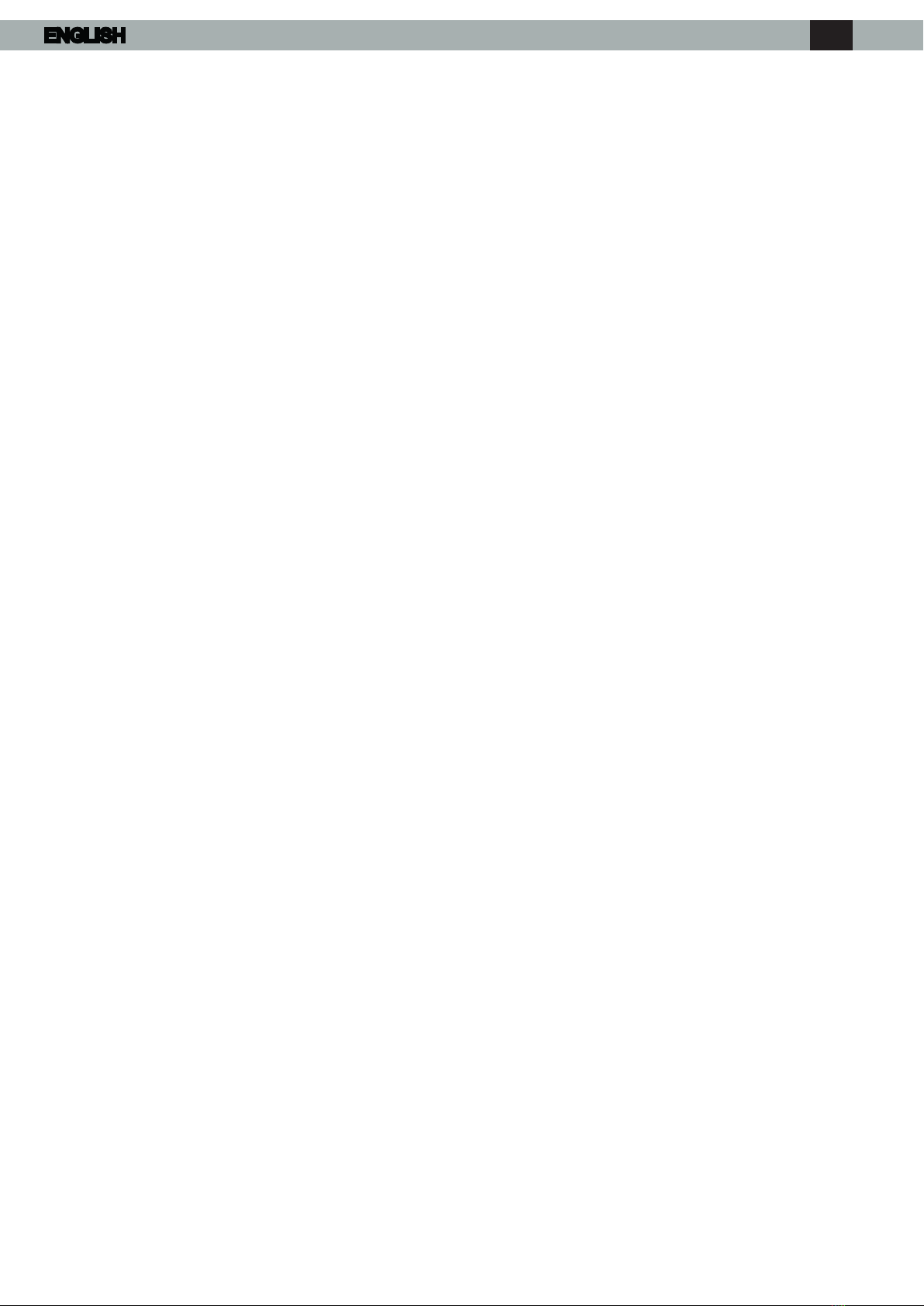
5. Transport and handling
During transport and storage the cooling unit
must be kept in a vertical position, as indicated
on the packaging (gure F.01), and must not be
exposed to temperatures above 70°C or below
-30°C. Upon receipt, check that the packaging
has not been damaged during shipping.
To lift the cooling unit in a safe manner, use the
handling brackets installed on the top of the unit
(gure F.03).
6. Installation
Installation of the unit should only be performed
by qualied and authorised personnel.
The cooling unit must be installed with the en-
closure air intake hole in the highest possible
point.
Ensure the xing elements and couplings will
not interfere with the equipment inside the en-
closure itself.
The unit must be installed in the vertical position
indicated. Maximum permitted deviation from
the vertical is 2°.
Disconnect power before starting any work in-
side the switchboard.
The cooling unit must be installed on the outside
of the electrical switchboard using the stand-
ard accessory kit supplied with the unit. Drill the
holes and make the cuts required in the switch-
board (gure F.04) using the supplied drilling
template.
Fit the sealing strip on the cooling unit on the
side connected to the enclosure and follow the
assembly diagram (gure F.04).
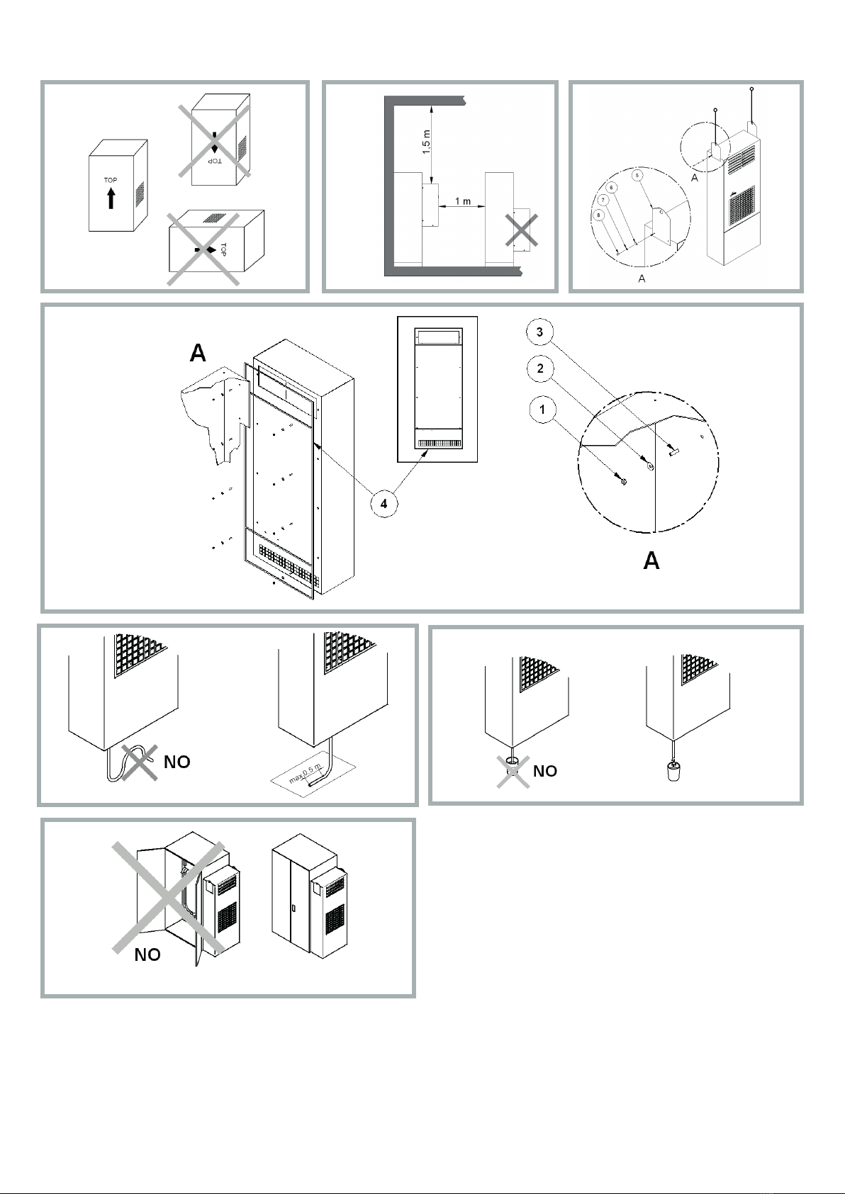
7. Condensate discharge hose
The condensate which, depending on the ambi-
ent temperature and humidity conditions, forms
on the heat exchanger which cools the enclo-
sure air, is not a malfunction but a normal phe-
nomenon of the cooling unit.
The condensate is taken outside the cooling unit
via a hose at the bottom of the unit (gure 11.B).
A plastic hose must be connected to this outlet to
carry the condensate to another point, allowing it
to be discharged where there can be no slipping
hazard for personnel.
In this case, make sure the condensate ows
without any hindrance. Avoid horizontal lengths
of more than 0.5 metres, uphill sections and the
accidental formation of traps (gure F.05). The
end of the condensate discharge hose must al-
ways be free and not underwater, so never place
the end of the discharge hose inside a conden-
sate collection container (gure F.07).
The condensate drain connection can also be
taken out the side of the cooling unit by modi-
fying the position of the internal rubber tube (g-
ure F.11A).
If the cooling unit is used with the doors of the
enclosure open, excessive quantities of conden-
sate will form and this is an unauthorised condi-
tion of use (gure F.07). We suggest using a po-
sition switch on the door connected to the cool-
ing unit’s digital input to stop the unit if the door
is opened. (See section 8.2)
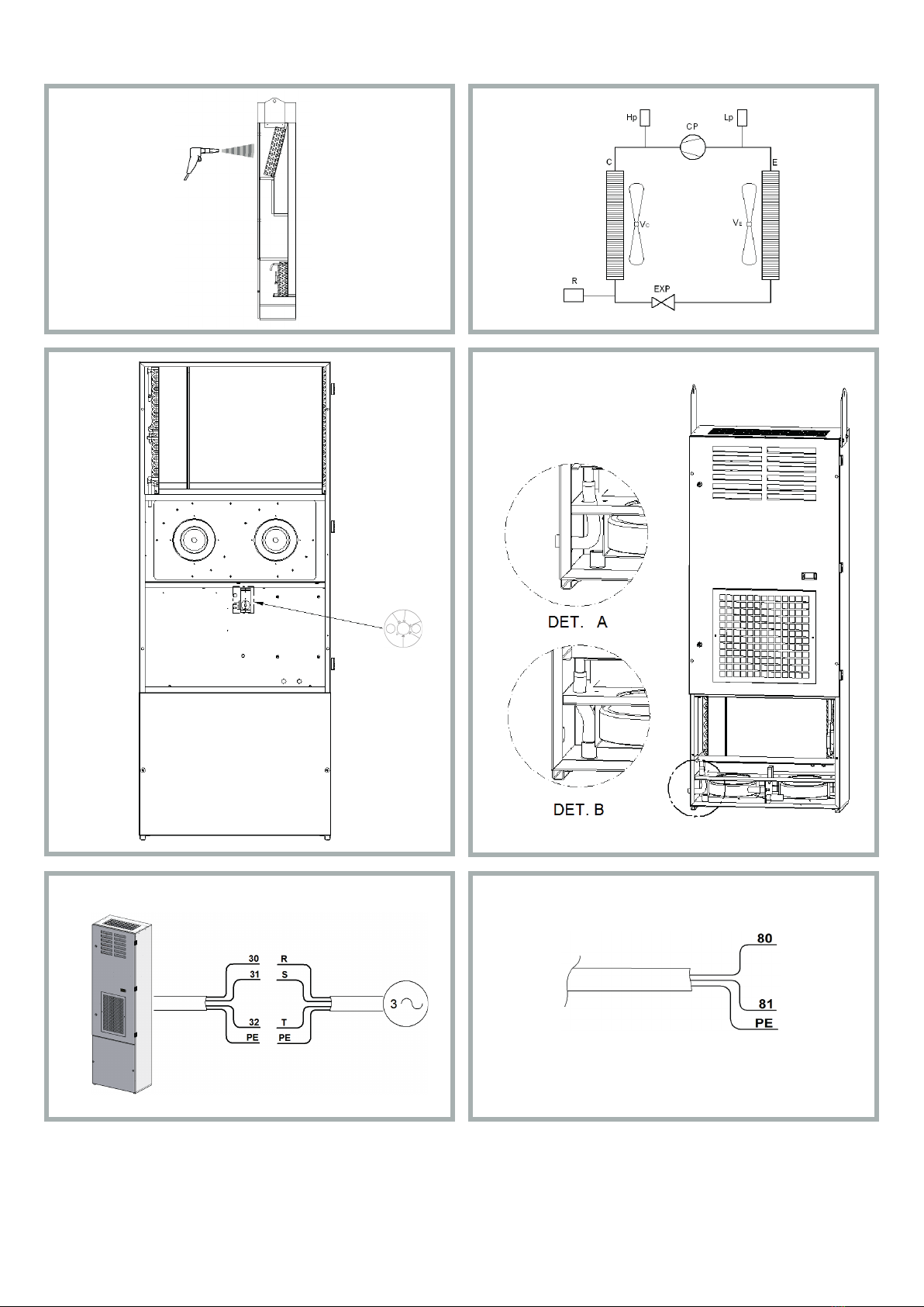
8. Electrical connection
8.1 Safety
Warning! Electrical connections must only
be performed by specialised and authorised
personnel. Switch power off to the enclosure
before making the connection. Check that
there is no power to the switchboard and that
the supply voltage corresponds to the character-
istics given on the cooling unit’s data plate. The
power supply must be protected using appropri-
ate time-delay fuses (type T) or circuit breakers
with K-curve, as per the indications given in table
F.14. Connect the power-supply cable as shown
in gure F14. Ensure you respect the sequence
R-S-T. Disconnect the cooling unit before per-
forming testing on the enclosure.
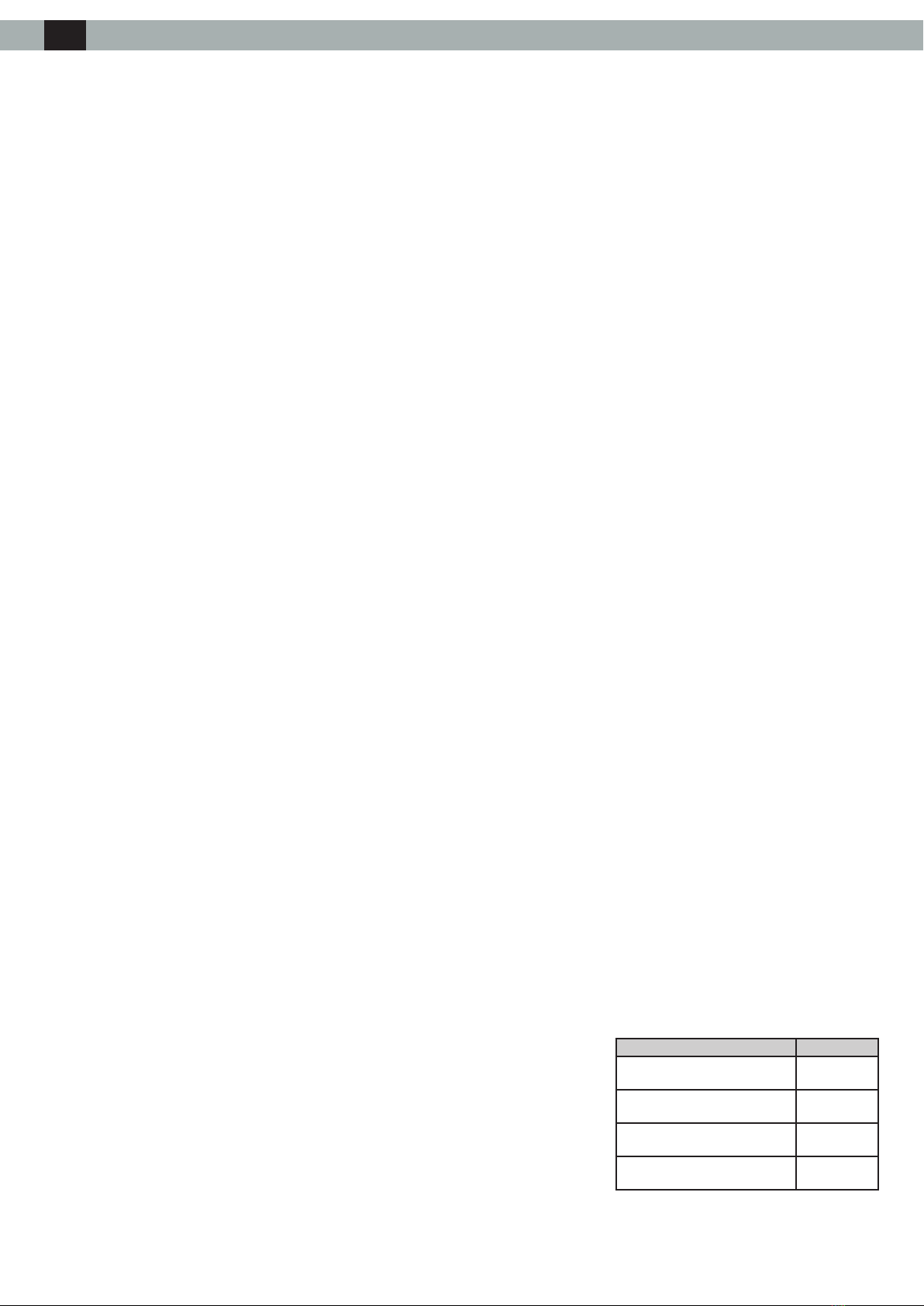
8.2 Alarm management cable
(gure F.13)
The alarm signal output from the cooling unit can
be taken from wires 80 and 81 using a two-pole
cable
9. First start up and adjustment
If, prior to installation, the cooling unit was left in
an incorrect position (gure F.01), wait at least 8
hours before switching it on. Otherwise, 30 min-
utes is more than enough time for the oil to re-
turn to the compressor, after which the cooling
unit can be powered up. The enclosure air intake
fan starts working immediately, making the tem-
perature inside the enclosure even.
If this temperature exceeds the set point on the
regulator thermostat, both the compressor and
external air fan will turn on, causing the cool-
ing cycle to start. This then stops when the in-
side temperature reaches the lower limit of the
operating temperature differential, which has a
xed value of 4 K. The thermostat is factory-set
to 35°C. Use the thermostat located inside the
cooling unit to adjust the temperature set-point.
The graduated scale allows you to set the re-
quired temperature between 20 and 46 °C (g-
ure F.10). In order to save energy and minimise
the production of condensate, it is nevertheless
recommended it not be set below 30 °C.
10. Maintenance
Warning! Caution! Before embarking on any
maintenance work, cut the current to the en-
closure.
The cooling unit is the low maintenance type.
The only maintenance required is for the internal
components, which should be checked regular-
ly, as indicated in the table given in this section,
and cleaned with compressed air at a maximum
pressure of 4 bar (gure F.08). Any repairs that
may need doing must only be performed by spe-
cialised and authorised personnel.
Job Frequency
Check, clean and, if necessary,
replace the air lter
Every 2
weeks
Check the external air heat
exchanger and clean if necessary.
Every 3
months
Check effectiveness of the con-
densate discharge.
Every 3
months
Check the fans for any overheat-
ing or excessive vibrations.
Every 6
months
ENG

11. Technical information
11.1 Operating principle
The cooling unit for electrical switchboard enclo-
sures works on the basis of a refrigeration circuit
consisting of four main components: compressor,
evaporator, condenser and expansion device
(gure F.09). The circuit is hermetically sealed
and the refrigerant circulates inside it. The refrig-
erant used, depending on the cooling unit model,
is R134a, R407C or R410a, all chlorine free and
harmless to the ozone layer. The unit is divided
into two hermetically separated sections where
the ambient air and enclosure air do not come in-
to contact with one another and are treated sep-
arately. The compressor (CP) compresses the
refrigerant, taking it to a high pressure and high
temperature. The compressor then pushes the
refrigerant through a heat-exchanger coil, called
the condenser (C), where it is cooled by ambi-
ent air, thus passing from the gas to the liquid
state. In this state it then collects in the receiver
(R), from which it then passes through the ther-
mostatic expansion valve (EXP), where it vapor-
ises. It is then received by the heat exchang-
er coil, called the evaporator (E), by means of
which it absorbs heat from the enclosure air and
passes from a liquid state to gas. The enclosure
is cooled down in this manner. The gaseous re-
frigerant is then drawn back into the compressor
and this cycle is repeated.
11.2 Safety devices.
The refrigeration circuit is tted with a high-pres-
sure pressure switch Hp and a low-pressure
pressure switch Lp (gure F.09) set to the max-
imum and minimum working pressures, respec-
tively, of the cooling unit. If one of these thresh-
olds is exceeded, the pressure switch stops the
compressor’s operation. They reset automatical-
ly. The fans and compressor have an (internal or
external) thermal cut-out switch that stops them
in the case of overheating.
11.3 Energy savings
To optimise energy savings, the cooling unit is
tted with a pressure-switch speed regulator
(RLF) which adjusts the speed of the condens-
er fans based on the pressure in the refrigera-
tion circuit, which in turn depends on the ambi-
ent temperature.
11.4 Disposal
Caution! The cooling unit contains R134a,
R407 or R410A refrigerant, depending on the
model, as well as small quantities of lubri-
cating oil. These are polluting substances and
must not be dumped. Replacement, repairs and
nal disposal must be performed by experts.
NOTE
Keep the unit’s documentation in a safe, dry
place.
Remedy
This is not a malfunction of the cooling unit.
To verify functioning when testing, lower the thermostat setting until
the compressor and external fan start working and then reset the
thermostat.
Change the adjustment (or antifreeze) thermostat
This is not a malfunction of the cooling unit.
Make sure the power cable has been connected well to the
terminals.
Check that the cubicle doors and switches are closed
Call a refrigeration expert or the Manufacturer’s Technical Assist-
ance Service
Call a refrigeration expert or the Manufacturer’s Technical Assist-
ance Service
Change the internal fan’s capacitor
Change the internal fan
Change the amperometric protector
Change the relay or PTC for compressor starting
Change the capacitor for compressor starting
Call a refrigeration expert or the Manufacturer’s Technical Assist-
ance Service
Call a refrigeration expert or the Manufacturer’s Technical Assist-
ance Service
Change the contactor
Change the cooling unit with another of greater capacity
Clean the evaporator coil
See if there are any obstacles inside the enclosure to hinder the
ow of recycling air
Call a refrigeration expert or the Manufacturer’s Technical Assist-
ance Service
Check thermostat setpoint
Ventilate the premises where the enclosure is installed to keep
ambient temperature lower.
Clean the exchanger with compressed air and detergent
Ventilate the premises where the enclosure is installed to keep
ambient temperature lower.
Clean the coil with compressed air and detergent
This is not a malfunction of the cooling unit. Close the enclosure
door or disable the cooling unit
This is not a malfunction of the cooling unit. Seal enclosure open-
ings, e.g. for passage and upward path of wires
Check seal and remedy
Causes
The temperature inside the enclosure is lower than what
is set on the adjustment thermostat.
The adjustment (or antifreeze) thermostat has failed
No electricity getting to the unit.
Cooling unit empty of uid
Compressor mechanical failure
Internal fan capacitor failed
Internal fan failed
Compressor’s amperometric protector failed (external to
the compressor, where present)
Relay or PTC for compressor starting failed
Capacitor for compressor starting failed (where present)
Compressor motor electrical failure
High pressure safety switch failed
Compressor contactor failed (where present)
Cooling unit under sized for the heat dissipated inside
the enclosure
Antifreeze thermostat triggered (where present)
Insufcient gas in the cooling unit
Thermostat set point incorrect
High pressure safety switch triggered:
Ambient temperature over the maximum work-
ing limit
Heat exchanger coil (condenser) either dirty or
clogged
Thermal protector inside the compressor triggered:
Ambient temperature over the maximum work-
ing limit
Heat exchanger coil (condenser) either dirty or
clogged
Too much ambient air inside the enclosure
Enclosure protection level is below IP54
The enclosure/cooling unit connecting seal has been
tted incorrectly
Conditions
The internal fan works, the external fan and com-
pressor do not work.
No component works
Compressor, external and internal fan work
Compressor and external fan work, internal fan
does not work
External and internal fan work, compressor does
not work
External and internal fans work, compressor works
all the time
Inside fan works, external fan and compressor
work irregularly
External and internal fans work, compressor works
irregularly
Enclosure door open
Enclosure door closed
Malfunction
It fails to cool
It is not cooling enough
Too much condensate forming
•
•
•
•
•
•
•
•
12. Troubleshooting
•
•
•
•
ENG
13. Pictograms
F.01 F.03
F.04
F.06
External Mounting
Montaggio Esterno
Außenmontage
Montage externe
Montaje externo
F.07
F.02
F.05
13. Pictograms
F.08 F.09
F.10 F.11
F.12 F.13

P(W)
Useful cooling output
Ta (°C)
Ambient temperature
Ti (°C)
Enclosure internal temperature
15. Performances
F. 15
EMO80M / EMO80N EMOA0M / EMOA0N
16. Dimensions
F. 16
EMO80M / EMO80N / EMOA0M / EMOA0N

17. Spare parts / Ricambi / Ersatzteile / Pièces détachées / Piezas de repuestro
F. 17
EMO80M / EMO80N EMOA0M / EMOA0N
1Evaporator fan
2Condenser fan
3Front structure
4Evaporator
5Condenser
6Compressor
7Autotransformer
8Assembly
accessory kit
ENG
This manual suits for next models
4
Table of contents


