Bracco ACIST CVi CMS2000 User manual

ACIST Contrast Delivery System
User Manual
900468-001, 02 2010-01
and CMS2000 and E2000Voyager™

This page intentionally left blank.

Table of Contents
Table of Contents
P/N 900468-001 Rev. 02 ACIST Medical Systems, Inc. i
Information & Warnings......................................................................................v
Contract Information ...........................................................................................................v
Contact and Ordering Information....................................................................................... v
About this manual..............................................................................................vi
Product Definition............................................................................................................... vi
Intended Use...................................................................................................................... vi
Disclaimers ........................................................................................................................ vi
IntendedUse/Indication .....................................................................................................viii
Contra-indications.............................................................................................................viii
Warnings ...........................................................................................................viii
AIR COLUMN DETECT SENSOR....................................................................................viii
AIR EMBOLISM................................................................................................................viii
AIR IN THE MONITORING LINE......................................................................................viii
CABLES............................................................................................................................viii
CATHETERS ..................................................................................................................... ix
CLEANING......................................................................................................................... ix
ELECTRICAL ISOLATION................................................................................................. ix
FLAMMABLE GASES........................................................................................................ ix
HIGH FLOW RATE INJECTIONS...................................................................................... ix
INJECTION SYSTEM SETTING........................................................................................ ix
MOUNTING SYSTEM........................................................................................................ ix
PROPER USE OF PATIENT KITS..................................................................................... ix
SHOCK HAZARD .............................................................................................................. ix
SYSTEM MESSAGES........................................................................................................ x
Precautions..........................................................................................................x
ACCESSORIES.................................................................................................................. x
PATIENT TABLE (BED) RAIL MOUNT ............................................................................... x
CONTROL PANEL TOUCH SCREEN ................................................................................ x
ELECTROMAGNETIC/ELECTROSTATIC INTERFERENCE............................................. x
EXCESSIVE INJECTIONS ................................................................................................. x
EYE PROTECTION ............................................................................................................ x
INJECTION SYSTEM TEMPERATURE ............................................................................. x
LEAKAGE CURRENT......................................................................................................... x
LINE POWER .....................................................................................................................x
LOCK BUTTON .................................................................................................................. x
LOCKING WHEELS........................................................................................................... xi

SALINE PUMP................................................................................................................... xi
PREVENTATIVE MAINTENANCE..................................................................................... xi
PROPERTIES OF CONTRAST......................................................................................... xi
THE MOUNTED INSTRUMENT........................................................................................ xi
TRAINING.......................................................................................................................... xi
Section 1: System Overview..............................................................................1
Introduction ......................................................................................................................... 1
System Components, Hardware......................................................................................... 3
System Components, Disposables..................................................................................... 5
Injector Head Electronics.................................................................................................... 7
The Computer System........................................................................................................ 7
Injection Motor Control........................................................................................................7
Saline Pump Control...........................................................................................................7
Standby Button ................................................................................................................... 7
Armed Light......................................................................................................................... 7
Control Panel Cable Connection......................................................................................... 8
Hand Controller Connection................................................................................................ 8
Touchscreen Display........................................................................................................... 8
The AngioTouch®Hand Controller ..................................................................................... 8
The ACIST Angiographic Kit ............................................................................................... 9
Kit components include: ..................................................................................................... 9
Contrast Media Requirements ............................................................................................ 9
Cables for Standard Power Supply..................................................................................... 9
Cables for Siemens Axiom Artis Imaging System ............................................................. 10
Description of Accessory Items......................................................................................... 10
Patient Kits........................................................................................................................ 11
ACIST Pressure Transducer Cartridge ............................................................................. 11
Pressure Monitoring Interconnect Cable........................................................................... 11
Section 2: Installation .......................................................................................13
Setup................................................................................................................................. 13
Installing the System ........................................................................................................ 13
Mounting Configurations................................................................................................... 13
Injector Head from Pedestal Cart to Patient table (bed) Mount (2 Options) .................... 14
Transfer Injector Head from Patient table (bed) Mount to Pedestal Cart (2 Options) ...... 15
Installing the CVi Adjustable Arm ..................................................................................... 16
Installing the CVi Utility Tray on all ACIST Systems .........................................................17
Installing the CVi Contrast Hanger on all ACIST Systems................................................ 17
Making Cable Connections............................................................................................... 18
Table of Contents
ii ACIST Medical Systems, Inc. P/N 900468-001 Rev. 02

Standard Power Supply .................................................................................................... 18
Power Supply Configured for Use with Siemens Systems ............................................... 20
Section 3: System Setup..................................................................................23
Section 4: About the Touchscreen..................................................................33
Contrast Usage Feedback Display ................................................................................... 33
Select Injection.................................................................................................................. 35
Injection Parameters......................................................................................................... 35
Injection Parameter Ranges Table.................................................................................... 36
Select Mode ...................................................................................................................... 36
Message Windows............................................................................................................ 38
Case Information...............................................................................................................38
System Info ....................................................................................................................... 39
Audible Indicators .............................................................................................................39
X-Ray Interface Parameters ............................................................................................ 39
Imaging System Status and Control Lines........................................................................ 40
Status Output Lines .......................................................................................................... 40
Input Control Lines............................................................................................................40
Section 5: Performing Patient Procedures............................................................41
Interface Devices ..............................................................................................................41
Operating the AngioTouch Hand Controller ...................................................................... 41
Pre-Procedure Tasks ........................................................................................................ 41
Pressure Monitoring.......................................................................................................... 43
Refilling the Syringe with Contrast.................................................................................... 45
Automatic Refill ................................................................................................................. 45
Manual Refill ..................................................................................................................... 45
Purging Air from Contrast Media Components ................................................................. 46
KVO Injection .................................................................................................................... 47
Resuming an Interrupted Case......................................................................................... 47
Ending a Case when using a Model CL100H ................................................................... 48
Ending a Case when Using a Model CMS2000, Voyager, or CVi..................................... 48
Starting a New Case with the Existing Syringe................................................................. 49
Starting Another Case with a New Syringe....................................................................... 49
System Shutdown............................................................................................................. 50
Section 6: System Maintenance.......................................................................51
Daily Cleaning................................................................................................................... 51
Clean the Sensors ............................................................................................................ 51
Clean and Inspect the Chamber Sleeve ........................................................................... 51
Table of Contents
P/N 900468-001 Rev. 02 ACIST Medical Systems, Inc. iii

Cleaning the Removable Backlight Cover ........................................................................ 52
Cleaning the Injector Head ............................................................................................... 53
Pressure Transducer Cartridge and Backplate ................................................................. 53
Decontamination ............................................................................................................... 53
Daily Status Inspection and Prevention ............................................................................ 54
Monthly Status Inspection................................................................................................. 54
Annual Preventive Maintenance Inspection...................................................................... 54
Storage of Cart Mounted Systems.................................................................................... 54
Section 7: Troubleshooting..............................................................................55
General Troubleshooting................................................................................................... 55
Emergency Shutdown Procedure ..................................................................................... 55
Problems with ACIST In-Line Pressure Monitoring........................................................... 56
Frequently Asked Questions ............................................................................................. 57
Functional Errors...............................................................................................................57
Alert Messages ................................................................................................................58
Section 8: Specifications..................................................................................69
System Control .................................................................................................................69
Power Requirements ........................................................................................................ 69
Electrical Leakage.............................................................................................................69
Safety and Sensor Checks ............................................................................................... 69
Injection Parameter Ranges ............................................................................................. 70
Saline Rate ....................................................................................................................... 70
Status Readouts ...............................................................................................................70
Program Control................................................................................................................70
Height................................................................................................................................ 70
Weight............................................................................................................................... 71
Cord Lengths .................................................................................................................... 71
Specifications that Apply to UL Labeled Product .............................................................. 71
Transportation and Storage Requirements....................................................................... 71
Operating Environment Requirements.............................................................................. 71
Section 9: Voyager and CVi Supported Imaging Systems ............................72
Section 10: Warranty Information....................................................................73
CL100H/CMS2000 Limited Warranty ............................................................................... 73
Voyager™ E2000 and ACIST CVi Limited Warranty......................................................... 74
Section 11...........................................................................................................76
Symbols ............................................................................................................................ 76
Table of ContentsTable of Contents
iv ACIST Medical Systems, Inc. P/N 900468-001 Rev. 02
Contact and Ordering Information
Information & Warnings
Contact Information
Information & Warnings
P/N 900468-001 Rev. 02 ACIST Medical Systems, Inc. v
Contact Information
USA EUROPE ASIA PACIFIC, LATIN AMERICA, OR
MEXICO
ACIST Medical Systems
7905 Fuller Road
Eden Prairie, MN 55344
USA
ACIST Europe B.V.
Becanusstraat 13
6216 BX Maastricht
The Netherlands
ACIST Medical Systems
7905 Fuller Road
Eden Prairie, MN 55344
USA
Customer Service
USA EUROPE ASIA PACIFIC, LATIN AMERICA,
OR MEXICO
Ordering patient kits 1-877-BRACCO.9 00800.2247.8387
+ 31.43.328.1318 Contact your localACIST distributor
FAX Number 1-866-272-1619 + 31.43.328.1329 Contact your localACIST distributor
Ordering systems and
accessories Call
952-941-3507 or
952-995-9300
for Representative
nearest you
00800.2247.8387
+ 31.43.328.1318 Contact your localACIST distributor
FAX Number FAX# 952-941-4648
or
FAX# 952-826-2895
+ 31.43.328.1329 Contact your localACIST distributor
Technical Support
Service, Parts and
Technical Support 1.888.670.7701
or
952.941.3507
or
952-995-9300
00800.2247.8387
or
+ 31.43.328.1318
Contact your localACIST distributor
FAX Number 952-253-4524 + 31.43.328.1329 Contact your localACIST distributor

About this manual
This manual is intended to guide you in the proper installation, use, and care of the
ACIST®injection system. The manual contains information for all users of ACIST
injection systems, whether you set the controls, direct its use, or interpret its results.
Also refer to the Instructions for Use provided with ACIST patient kits (the syringe,
manifold, tubing, hand controller, etc.) for setup instructions and specific warnings
and cautions.
Product Definition
The ACIST injection system is an angiographic injection system that supplies
radiopaque contrast media to a catheter at a user-determined variable flow rate and
volume which can be instantaneously and continuously varied.
The ACIST injection system is designed to comply with MDD/93/42 EEC and EN
60601-X series of safety standards for medical electrical equipment.
Intended Use
The ACIST injection system is intended to be used for the controlled infusion of
radiopaque contrast media for angiographic procedures.
Disclaimers
ACIST Medical Systems reserves the right to change specifications and contents of
this manual without obligation.
Protected by one or more of the following U.S. patents and international
counterparts: 5,515,851; 5,573,515; 5,800,397; 5,882,343; 5,916,165; 6,221,045;
6,344,030; 6,447,481; 6,626,862; 6,656,157; 6,673,048; 6,746,427; 6,752,789;
6,945,959; 7,101,352; 7,128,729; 7,169,135; D404,717; D412,205. Other U.S. and
international patents pending.
© Copyright 2007 by ACIST Medical Systems, Inc.
Manufactured by:
ACIST Medical Systems, Inc.
7905 Fuller Road
Eden Prairie, MN 55344 USA
Authorized European Representative:
Medical Product Service GmbH
Borngasse 20
35619 Braunfels, Germany
AngioTouch and ACIST are trademarks of ACIST Medical Systems, Inc., reg-
istered in the United States.
ACIST is a trademark of ACIST Medical Systems, Inc., registered in the
United States.
About this Manual
Information & Warnings
vi ACIST Medical Systems, Inc. P/N 900468-001 Rev. 02

Caution and Safe Use
Federal Law (USA) restricts the sale of this device by or on the order of a physician
(or properly licensed practitioner).
For proper operation, use only accessories and options provided by ACIST
Medical Systems, which are designed specifically for the ACIST Angiographic
Contrast Delivery System. This ensures compatibility with the injector. Do not use
an accessory or option designed for another system on the ACIST Angiographic
Contrast Delivery System.
SAFE USE
ACIST Angiographic Contrast Delivery System is designed to aid the physician in
the injection of contrast media during angiography. It should be used with adequate
radiographic imaging and where monitoring equipment for blood pressure and the
electrocardiogram is available. Additionally, standard equipment for cardiopulmonary
resuscitation and drugs for the treatment of contrast media-induced drug reactions
should be present.
Due to the type of procedures in which the ACIST System is used, (angio-
graphic studies of human cardiovascular and central venous systems) or
procedures in interventional radiology or in endovascular surgery), it is nec-
essary that the ACIST system be operated by, or be under the immediate
and direct supervision of a physician who is specifically trained in angiogra-
phy and in the operation of this unit. System operation must be monitored
at all times, and specific operational and mechanical integrity must be
maintained to ensure patient safety.
Support personnel must ensure that:
• All system connections are in place, secure, and functional
• Proper grounding and isolation standards are maintained
• Operational and calibration checks are made prior to each use of the system
• Proper support equipment (for example, defibrillation unit, etc.) is on site for
immediate response to patient distress.
PHYSIOLOGICAL PRESSURE TRANSDUCER (OPTIONAL)
Attach the pressure transducer cartridge to the pressure transducer backplate
before application of any pressure to the system. This prevents pressures from
bursting the membrane and introducing air into the system.
Note: Prior to recording physiological blood pressures with the transducer system,
re-zeroing of the transducer is recommended to establish a clear baseline.
(Changes in bed height, catheter hub position, fluid density, etc. can affect the
baseline pressure.)
Note: Prior to recording physiological waveforms with the transducer system, a
saline flush is recommended to clear contrast from the tubing. (Any contrast in
the tubing will damp pressure signals.)
CAUTION:
Information & Warnings
P/N 900468-001 Rev. 02 ACIST Medical Systems, Inc. vii
Information & Warnings
viii ACIST Medical Systems, Inc. P/N 900468-001 Rev. 02
Please read and understand all the following warnings and
precautions before proceeding with installation, setup and
operation of the ACIST system.
Warnings
AIR COLUMN DETECT SENSOR
The ACIST System is equipped with an air column detect sensor. This sensor is
designed to aid the user in the detection of air columns in the injection line, but it is
not designed to replace the vigilance and care required of the operator in visually in-
specting for air and clearing air from the entire patient kit and angiographic catheter.
The air column detect mechanism is to be used in conjunction with and to comple-
ment the user’s other procedures for preventing air injections.
AIR EMBOLISM
An air embolism can cause patient injury or death. Operator vigilance and care,
combined with a set procedure, are essential to avoid injecting air and causing an
air embolism. Before injecting, be sure to clear air from the entire patient kit and
angiographic catheter. Make sure the exterior of the tubing is dry before inserting it
into the air column detect sensor; if any fluid is present, they may inhibit the ability of
the sensor to detect air.
AIR IN THE MONITORING LINE
When using a blood pressure monitor, be sure to clear the monitoring line of all air to
avoid producing an inaccurate blood pressure reading.
CABLES
Be sure to plug each cable into the correct connector. Never touch the pins on
the connector or cable (See “Making Cable Connections on Page 18”). Do not
use the ACIST system if any worn cords or cables are detected. For replacement
information, Contact an ACIST representative.
Intended
Use/
Indication
The ACIST Injection System is intended to be used for the controlled infusion of
contrast media for angiographic procedures.
Contra-
indications
ACIST Angiographic Contrast Delivery Systems are not intended for use as a long-
term infusion pump nor is it intended to be used to inject any agents other than
contrast media. ACIST Angiographic Contrast Delivery Systems should not be used
to inject substances into nonvascular body cavities.
Any applications of the ACIST Angiographic Contrast Delivery Systems (other than
those described in the user manual) are inappropriate and should not be attempted.
Do not add any components (e.g., manifolds, connector tubing) into the ACIST
disposable kits or in conjunction with the catheter. No valves or other manifolds may
be placed in-line between the ACIST Angiographic Kit and catheter. The disposable
kits are designed, manufactured, and tested for connection to catheters used in
angiographic procedures.
Do not use ACIST Angiographic Contrast Delivery Systems in the presence of
flammable gases.
Intended Use and Contraindiations

Information & Warnings
P/N 900468-001 Rev. 02 ACIST Medical Systems, Inc. ix
Warnings
CATHETERS
Connections to the patient are to be made from commercially available catheters
that have been approved for angiographic studies. For information on pressure
settings and limits, refer to instructions provided by the catheter manufacturers.
CLEANING
To avoid shock and prevent damage to the ACIST system, always disconnect it
from line power before cleaning. Do not use excessive water when cleaning. Do not
immerse any components in water. Be sure that the ACIST system is completely dry
before applying power. For more information, see “System Maintenance,” starting on
page 51.
ELECTRICAL ISOLATION
Connections to the patient are physically isolated from all ACIST system power
sources. Follow standard health care facility procedures to ensure that there is no
degradation of system electrical performance.
FLAMMABLE GASES
Do not use the ACIST system in the presence of flammable gases.
HIGH FLOW RATE INJECTIONS
High flow rate injections can cause patient injury or death. Use extreme care when
setting the flow rate to avoid unintentionally setting a high flow rate injection. When
high flow rate injection is required, be sure to select a pressure setting that does not
exceed the rated pressure of the selected catheter.
INJECTION SYSTEM SETTING
Check the ACIST system settings before injection, and verify appropriateness of all
injection parameters before injecting.
MOUNTING SYSTEM
The system must be mounted using ACIST approved mounting assemblies, such as
the Pedestal cart (see page 12) or the Patient Table (Bed) Rail Mount (see page 12).
Use of non-approved mounting equipment may cause injury.
PROPER USE OF PATIENT KITS
• Do not use the patient kits on more than one patient.
• Do not allow the disposables to sit, without use, for more than the maximum
time recommended by the contrast manufacturer.
• Do not reuse the syringe kit with the CL100H system.
• Do not use the multi-procedural syringe kit with the CMS2000 or Voyager for
more than five (5) procedures.
• Do not allow the syringe kit to sit loaded with contrast longer than the maximum
time recommended by the contrast manufacturer.
• Do not use the multi-procedural syringe kit for more than five (5) procedures.
• Replace the automated manifold and hand controller kits after each procedure.
• Properly discard disposables in accordance with all local, state, and federal
regulations, codes and directives.
SHOCK HAZARD
Hazardous voltage exists within the ACIST system. To avoid shock, only trained,
qualified service personnel should service the ACIST system. Always disconnect
the system from line power before attempting to perform any maintenance. Never
touch any pins on connectors or cables that have become disconnected from a live
system.
Information & Warnings
x ACIST Medical Systems, Inc. P/N 900468-001 Rev. 02
SYSTEM MESSAGES
Respond appropriately to all system messages. If the message cannot be cleared,
contact an ACIST representative. For more information, see “Troubleshooting,”
starting on page 58.
Precautions
ACCESSORIES
For proper operation, use only accessories and options provided or specified by
ACIST Medical Systems which are designed specifically for the ACIST system. This
ensures compatibility with the device.
PATIENT TABLE (BED) RAIL MOUNT
Failure to securely clamp the instrument to the patient table (bed) may result in
serious injury. For optimal displacement of weight, the ACIST system should be
mounted per the bed manufacturer’s recommended placement. Before mounting
the ACIST system on the bed, consult bed specification to ensure that bed rails can
support the system.
CONTROL PANEL TOUCH SCREEN
Touch the touchscreen in one place only when programming. If the touchscreen is
touched in two places simultaneously, a selection located at the midpoint between
them may be inadvertently activated or selected.
ELECTROMAGNETIC/ELECTROSTATIC INTERFERENCE
The ACIST system may fail to operate appropriately if exposed to high
electromagnetic fields (which may be generated by sources such as radio
transmitters and cellular phones), or to high levels of electrostatic discharge.
EXCESSIVE INJECTIONS
When doing a large number of high pressure, high-volume injections or a very large
number of low-pressure, low-volume injections, the manifold valve may begin to
stick when resetting or opening. If this occurs, replace the patient kit.
EYE PROTECTION
Always wear eye protection when using this device.
INJECTION SYSTEM TEMPERATURE
When the ACIST system is brought in from extreme outside temperatures (heat or
cold), allow it to stabilize at room temperature before use (approximately one hour).
LEAKAGE CURRENT
If the chassis leakage current is above 100 microamperes, do not use the ACIST
system. Contact an ACIST representative.
LINE POWER
Check for proper voltage and frequency before plugging the ACIST system into an
electrical outlet. Be sure the voltage selection plug on the power supply’s power
entry module is in the correct position before plugging into a wall outlet.
LOCK BUTTON
The ACIST system is locked to its mount when the locking knob is fully clockwise.
The system should always remain locked to its mount except during transfer
between mounts, e.g., when transferring from the patient table (bed) to the cart. For
more information, see “Mounting Configurations” on page 13.
Precautions
Information & Warnings
P/N 900468-001 Rev. 02 ACIST Medical Systems, Inc. xi
Precautions
LOCKING WHEELS
After moving the ACIST system using the pedestal cart, lock the wheels to prevent
unintentional movement when the cart is stationary.
SALINE PUMP
The tubing must be properly installed in the injector head and the locking V-teeth
engaged on the tubing for proper operation of the pump and system. (See page 28)
PRESSURE TRANSDUCER (OPTIONAL)
Attach the pressure transducer cartridge to the transducer backplate before
application of any positive pressure to the system. This prevents pressures from
bursting the dome membrane and introducing air into the system.
PREVENTATIVE MAINTENANCE
To ensure that your ACIST system is in optimal working condition, annual
preventative maintenance is recommended. Contact ACIST Medical Systems for
information on extended warranty options (see page 73).
PROPERTIES OF CONTRAST
For correct function of the ACIST system, make sure that the contrast has its
viscosity maintained between 26.6 centipoise and 4.6 centpoise for all functions at
the temperature used.
THE MOUNTED INSTRUMENT
Never lean, grab or place objects on the ACIST System. When transporting the
system, guide it using the pedestal cart handrail only. Do not grab or push on the
system itself. Make sure safety latch knob is tightened in the clockwise rotation and
the unit is secure on the cart. For power supplies that are off the patient table (bed)
mount, be sure that the power supply is in the cart tray during transportation.
TRAINING
ACIST Medical systems recommends instruction for all qualified persons prior to
operating of the ACIST system. A certified ACIST Medical systems representative
will conduct training.

Information & Warnings
xii ACIST Medical Systems, Inc. P/N 900468-001 Rev. 02
Introduction
Introduction
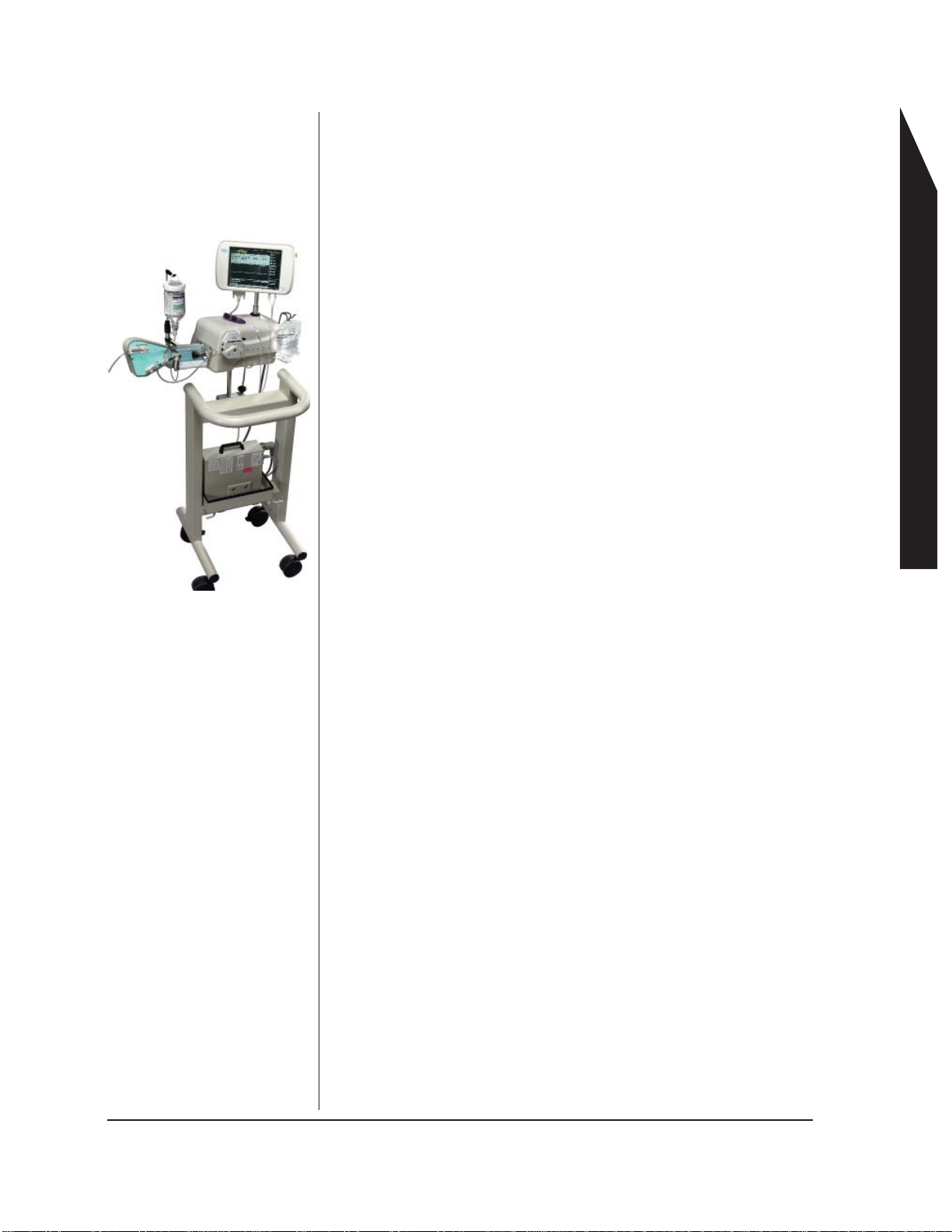
The ACIST®injection system is an angiographic injection system
used in interventional cardiology, radiology, and vascular surgical
procedures. The ACIST injection system supplies radiopaque
contrast media to a catheter at a rate that can be instantaneously
and continuously varied by the user. The ACIST injection system
contains the following primary components:
• Power supply
• Control panel
• Injector head
• Cables
Angiographic patient kits (also referred to as the “disposables”)
provide the interface between the ACIST injection system and
the angiographic patient catheter. Patient kits consist of several
components including a hand controller, high pressure (injection)
tubing, a syringe assembly, and a manifold assembly. For more
information on the patient kits used with the ACIST injection system,
see page 11. The patient kits are sold separately and can be ordered
from your ACIST distributor.
This document is designed to orient lab personnel in setting up,
using, and troubleshooting the ACIST injection system. Each part
of the system is described in detail in this manual. Step-by-step
procedures for using the system are also presented.
A More Detailed Look
The ACIST injection system contains a motor-driven pump that
delivers contrast media to a patient catheter. You can control the
flow rate of the contrast media using a user-actuated proportional
control device–the AngioTouch®Hand Controller. The hand controller
enables you to provide variable or fixed rate control when dispensing
contrast media. When using the variable rate feature, the system
allows you to vary the flow rate of the contrast media from the
injector while simultaneously observing the angiographic procedure
on a angiographic monitor.
Before the system is used, the patient kit disposables are loaded
onto the injector and the system is prepped with contrast and saline.
A touchscreen control panel allows you to uniquely configure the
various injection parameters.
The ACIST CMS2000, Voyager and CVi injection systems include
disposables that are designed to be used for multiple procedures. A
single syringe can be used in up to five cases. This reduces kit costs
and saves contrast that would normally be discarded at the end of
each procedure.
The ACIST Voyager and the ACIST CVi injection systems are able
to synchronize with certain X-ray imaging systems from Siemens,
Toshiba, GE, and Philips. (For specific models and series, refer to
Section 11. When interfacing to Siemens X-ray systems, a special
Siemens power supply is required (see “Making Cable Connections”
on page 18).
Section 1: System Overview
ACIST System Overview
P/N 900468-001 Rev. 02 ACIST Medical Systems, Inc.. Section 1 System Overview 1
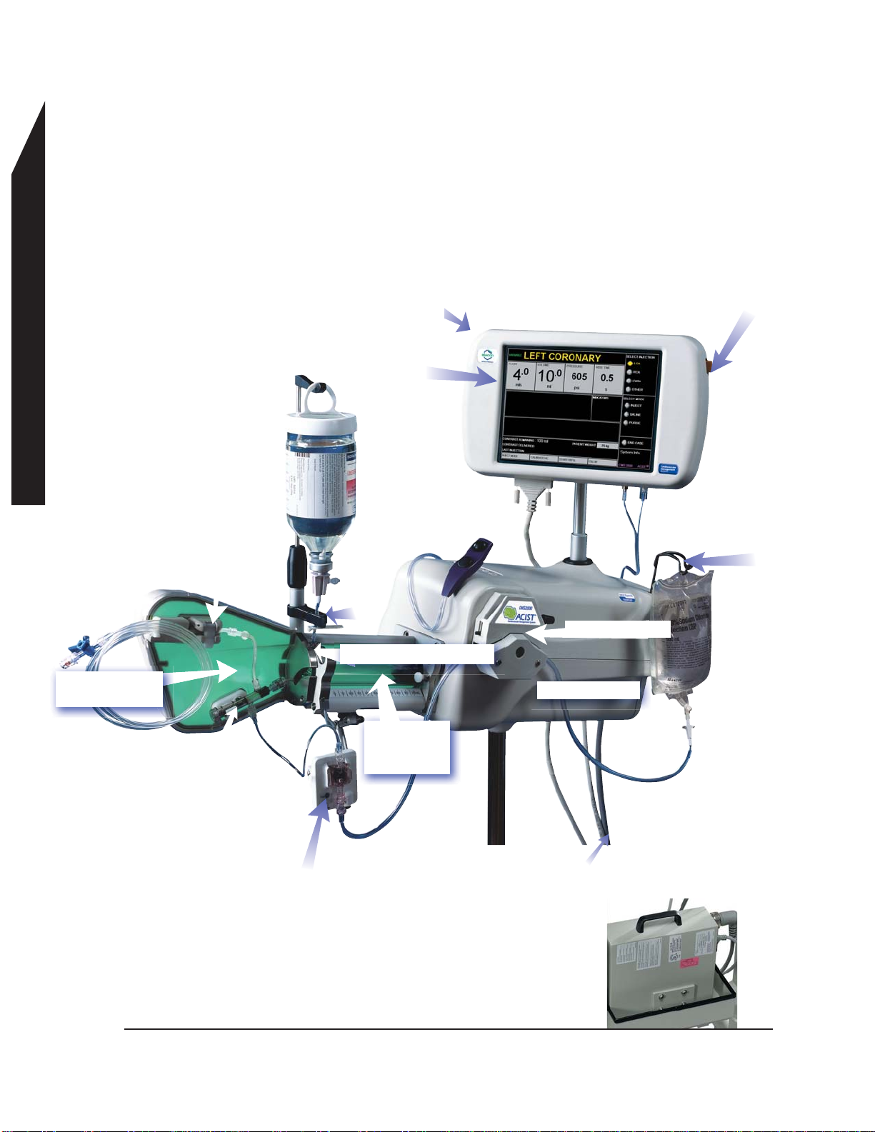
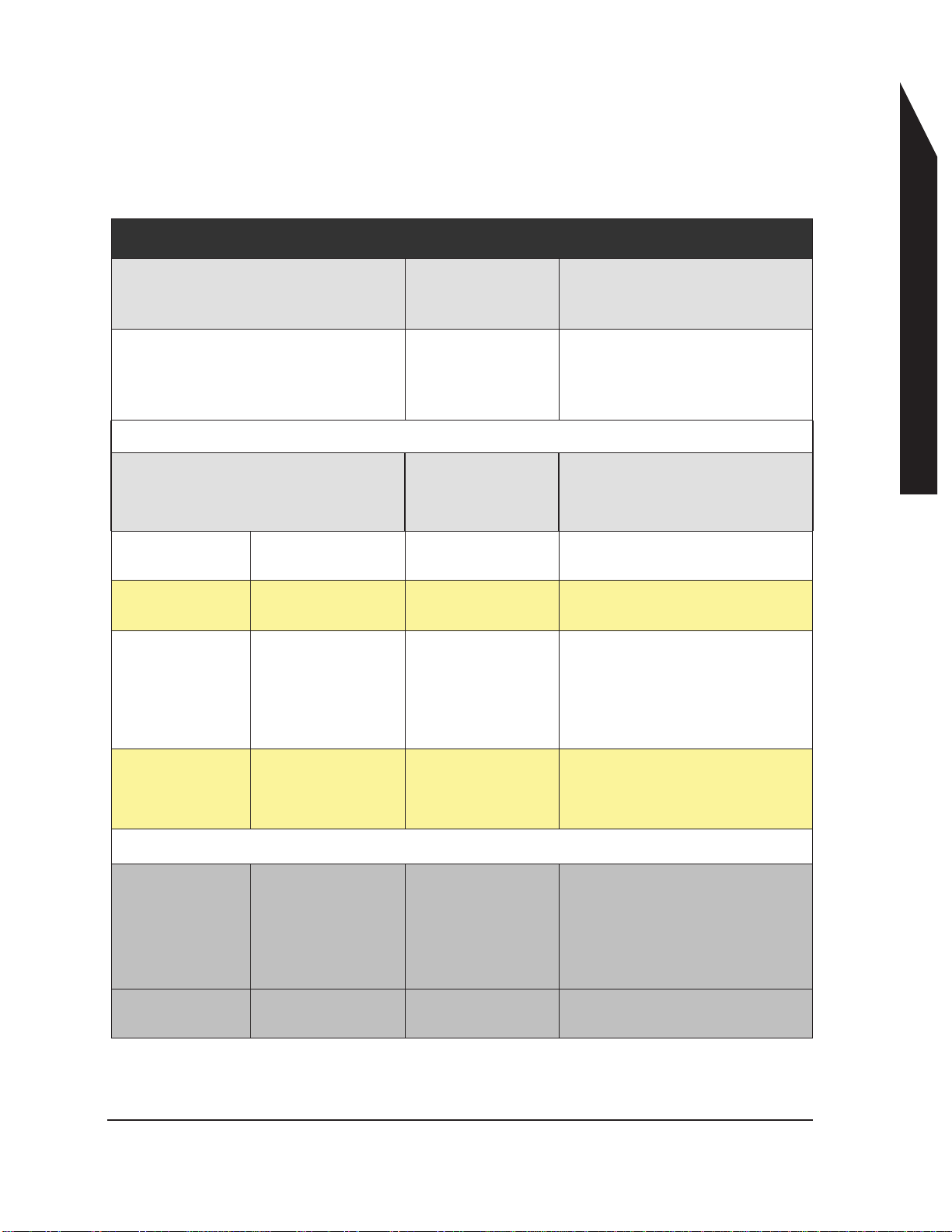
System Components, Hardware
System Components
5. Saline Pump
16. Pressure Transducer backplate and
disposable cartridge
4. Saline bag holder
2.Armed light
1. LCD Touchscreen
Display
10. Syringe Valve Sensor
3. Standby button
12. Universal or CVi
Contrast Hanger
11. Contrast
Sensor
13. Air Column
Detect Sensor
15. Manifold
clip and
sensor
8. Power Supply
9. Syringe
mounting
chamber
7. Cables
6. Injector Head
14. Luminescent
Backlight
ACIST System Overview
2 Section 1 System Overview ACIST Medical Systems, Inc. P/N 900468-001 Rev. 02

ACIST System Overview
P/N 900468-001 Rev. 02 ACIST Medical Systems, Inc. Section 1 System Overview 3
System Components
1. Control Panel with LCD Display
This is an interactive screen used to control injection parameters
and use of the device. This screen can be calibrated during
setup if needed.
2. Armed light
A green light on the top of the control panel that indicates the
system is armed and ready to inject.
(Note: On some systems, the armed light is on the right side of
the control panel.)
3. Standby button
When the Standby button is depressed, the system is
immediately disabled. Pressing the Standby button again
reverses the action.
4. Saline bag holder
For hanging the saline bag.
5. Saline (peristaltic) pump
Controls the flow of saline into the patient.
6. Injector Head: The part of the device that contains the
electroics, including the computer system, the injection motor
control, saline pump control, and the control panel.
7. Cables: Used to connect the various components of the system
8. Power supply: The power supply supplies power to the ACIST
System, and provides electrical safety isolation between the
main power and the ACIST System.
9. Syringe mounting chamber
The mounting chamber has demarcations to assist you in
determining the amount of contrast present in the syringe.
10. Syringe valve sensor
(Located on top of the mounting chamber; connection is plugged
in underneath) Detects if the system is ready to inject contrast to
the patient.
11. Contrast sensor
Detects if contrast remains for filling operations.
12. Universal or CVi contrast hanger
Holds the contrast container.
13. Air column detect sensor
An ultrasonic detection device used to aid the user in detecting
and preventing air from being introduced into the patient.
NOTE: The air column detect sensor is not a substitute for user
vigilance.
14. Luminescent back light
Located behind the syringe and disposable, the lighting
facilitates visual air column detection.
15. Manifold clip and sensor
Automatically switches between high and low pressure ports
eliminating the need to switch manifold stopcocks. Ensures that
the patient blood pressure is monitored any time fluid is not
being dispensed (when using a pressure transducer).
16. Pressure Transducer Backplate and Disposable Cartridge
(Optional)
Used for pressure measurement when mounted in the backplate.

System Components
25. Hand
Controller
18. High Pressure
(Injection) Tubing
20. Contrast
injection
syringe
24. Hand Controller
Connection
17. Contrast
Container
23. Saline
Bag
21.Disposable Pressure
Transducer Cartridge
System Components, Disposables
22. Saline Tubing
19. Automated
Manifold
26. Stopcock
ACIST System Overview
4 Section 1 System Overview ACIST Medical Systems, Inc. P/N 900468-001 Rev. 02

ACIST System Overview
P/N 900468-001 Rev. 02 ACIST Medical Systems, Inc. Section 1 System Overview 5
17. Contrast container
Contains the contrast media.
18 High pressure (injection) tubing
Connects with patient catheters for contrast or saline injection.
19. Automated Manifold: Regulates the distribution of contrast
media and saline.
20. Contrast Injection Syringe
The contrast syringe is a self-purging syringe and has one port
for filling of contrast and purging of air, and a second port for
injection of contrast.
21. Disposable Pressure Transducer Cartridge
22. Saline tubing
Carries saline from the saline bag.
23. Saline bag
For flushing the system and catheters through the use of the
saline pump.
24. Hand controller connection
Connects the hand controller to the touchscreen
25. Hand controller: The device used to inject contrast and to
dispense saline.
26. Stopcock: Regulates the flow of fluids to the patient.
CAUTION: Never mix and match hardware components from
different product models. Each model’s components
are designed to work together as a set.
In addition to the manufactured date label, newer
model ACIST hardware components also will carry this
label for easy identification:
The exception to this rule are the CVI Adjustable
Arm, the CVi Utility Tray and the CVi Contrast Hangar.
Instructions for installing these components on pages
16 and 17.
System Components

ACIST System Overview
6 Section 1 System Overview ACIST Medical Systems, Inc. P/N 900468-001 Rev. 02
The CL100H disposables are designed to be used per procedure
and this injection system does not have synchronization capability.
Available Models
• CL100H: This is an early model that is no longer available for
sale.
• CMS2000: The ACIST CMS2000 system is designed for
use in cardiac procedures to inject contrast into the patient’s
vasculature. This model does not synchronize with any X-ray
system
• VoyagerTM E2000: The ACIST Voyager E2000 is designed for
use in peripheral vascular procedures to inject contrast into the
patient’s vasculature.This model does synchroize with certain X-
ray systems. For specific models and series, refer to Section 9.
Note: Syrchronization is only possible provided the proper x-ray
interface cable is also purchased and installed with the
Voyager E2000.
• ACIST CViTM: The latest model available from ACIST Medical
Systems, the ACIST CVi combines the capabilities of the
CMS2000 and the Voyager E2000 on the same device. The
ACIST CVi may function in either in cardiac or peripheral modes
Peripheral mode provides x-ray sychronization feature. For
specific models and series of x-ray systems, refer to Section 9.
Note: Synchronization is only possible provided the proper x-ray
interface cable is also purchased and installed with the
ACIST CVi.
Available Models
This manual suits for next models
1
Table of contents
Popular Medical Equipment manuals by other brands


Solta Medical
Solta Medical Fraxel 1550 Operator's manual

GE
GE Vital Signs enFlow Service manual

Weinmann
Weinmann MEDUVENT Standard Instructions for use

Maico
Maico PILOT TEST Operation manual

BCD microtechnique
BCD microtechnique COVIDAIR S/T EASY quick start guide

Richmar
Richmar SoundCare Plus instruction manual